Table of Contents
Advertisement
Advertisement
Table of Contents
Troubleshooting

Related Manuals for AEC FP1000


Summary of Contents for AEC FP1000
-
Page 1: User Manual
User Manual FP Series UPS 1000VA-3200VA www.allis.com.tw... -
Page 2: Table Of Contents
Battery Modules With Charger(BMc) ............4 • 1.3 Front panel....................... 5 1.4 Rear panel......................6 FP 1000/ FP1500/ FP 2200/ FP 3000 (UL)............. 6 • FP1000/ FP1600/ FP2500/ FP3200 (CE)............7 • Extended Battery Module................9 • 2. Installation ......................10 2.1 Unpacking ...................... 10 2.2 Installation in rack position................ - Page 3 FP series user manual Contents 4. Maintenance ......................36 4.1 General Maintenance ..................36 Environment ................... 36 • Storing the UPS and battery ..............36 • When to replace the battery..............36 • 4.2 Battery Pack Replacement ................37 4.3 Testing new batteries ..................38 4.4 Recycling the used battery ................
-
Page 4: Safety Information
FP series user manual Safety information SAVE THESE INSTRUCTIONS. This UPS unit operates from utility power and contains a number of high current back-up batteries, the information is important to all personnel involved. Please read this manual first before unpacking, installation and operation of the UPS. CAUTION: Safety of persons Opening or removing the cover of the unit may expose you to lethal voltage within the unit even it is apparently not operated and the input wiring is disconnected from electrical source. -
Page 5: Limited Product Warranty And Policy
All claims under this warranty must be submitted in writing to AEC within 30 days of the occurrence or the claim will not be considered. This warranty does not include damage resulting from accident or misuse. -
Page 6: Presentation
FP series user manual 1. Presentation 1.1 General description In today’s world where power requirements are increasing, utility power quality and reliability is decreasing. Normal everyday routines are constantly exposed to power problems such as power outages, sags, or surges. Any of these problems can spell disaster for the unprepared. -
Page 7: System Configurations
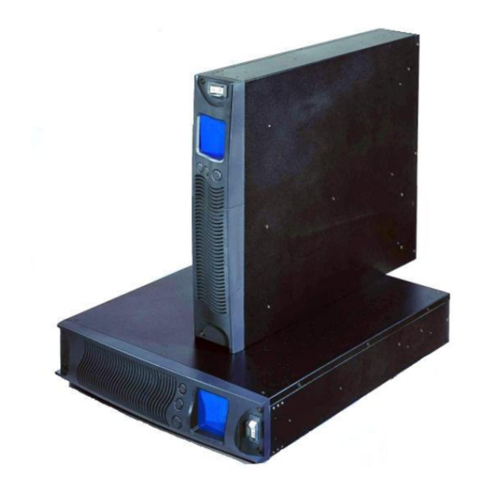
FP series user manual 1. Presentation 1.2 System configurations 1.2.1 Rack mount 2U (426 W × × × × 88 H × × × × 500 D mm) 4U (426 W × × × × 176 H × × × × 500 D mm) 8U (426 W ×... -
Page 8: Tower Standalone
FP series user manual 1. Presentation 1.2.2 Tower standalone 2U (88 W× × × × 426 H × × × × 500 D mm) 4U (176 W× × × × 426 H × × × × 500 D mm) 6U (264 W× × × × 426 H × × × × 500 D mm) Allis Electric - 3 - Rev3. -
Page 9: Single Voltage Battery Design
FP series user manual 1. Presentation 1.2.3 Single voltage battery design Battery Pack(BP) The 48VDC standard battery pack contains four 4 × 12V7AH lead-sealed acid batteries. It is used in all FP series UPS models and is interchangeable with each other. Battery Modules(BM) The battery module contains two(2) Battery Packs. -
Page 10: Front Panel
1.3 Front panel FP1000/FP1500/FP1600 1. Vent 2. Push Buttons 3. Graphic LCD Display 4. Input Breaker Switch • FP1000: 15A 125V (UL) or 10A 250V (CE) • FP1500: 15A 125V (UL) • FP1600: 10A 250V (CE) 5. Internal 48VDC Battery Pack FP2200/FP2500/FP3200 1. -
Page 11: Rear Panel
FP series user manual 1. Presentation 1.4 Rear panel FP 1000/ FP1500/ FP 2200/ FP 3000 (UL) FP1000/FP1500 1. Input Receptacle (15A 125V) 5. Battery Connector 2. Fan 6. Output Fuse (15A 250V) 3. Optional Communication Slot 7. Output Receptacle (NEMA 5-15R) 4. -
Page 12: Fp1000/ Fp1600/ Fp2500/ Fp3200 (Ce)
2. Output Fuse (15A 250V) 7. Fan 3. Output Receptacles (NEMA (1)5-15R; (1)L5-30R) 8. Battery Connector 4. Optional Communications Slot 9. Battery Cable 5. Standard RS232 FP1000/ FP1600/ FP2500/ FP3200 (CE) FP1000/ FP1600 Australian British French & German 1. Input Receptacle (10A 250V) 5. - Page 13 FP series user manual 1. Presentation Output Receptacle options for FP1000/ FP1600. 1.IEC TYPE 2. EUROPE TYPE FRENCH BRITISH GERMAN AUSTRALIAN FP2500/ FP3200 Australian British French & German 1. Input Receptacle (15A 250V) 6. Battery Circuit Breaker 2. Output Fuse (15A 250A) 7.
-
Page 14: Extended Battery Module
FP series user manual 1. Presentation Extended Battery Module How to plug in the battery connector ? Before plugging in battery connector, please make sure the UPS unit is off. This is a critical action to ensure the safety of the installer. How to add on the additional BM or BMc ? 1. -
Page 15: Installation
The FP-Series UPS can be supplied in a number of boxes depending upon the model ordered. The number of boxes should be as follows: MODEL (Box 1) BATTERY MODULE (Box 2) TOTAL BOXES FP1000/FP1500/FP1600 N/A (internal battery pack) 1 Box FP2200/FP2500/FP3000/FP3200 1 Battery Module... - Page 16 2. RS-232 communications cable 3. Cruiser software installation CD 4. User Manual (CD) 5. 2pcs mounting-feet for tower configuration 6. 2pcs 19” rack ears (+screws) for rack-mount configuration 7. Power Cord (for FP1000/FP1500/FP1600 only) Allis Electric - 11 - Rev3. July 2005...
- Page 17 FP series user manual 2. Installation FP 2200/FP2500/FP3000/FP3200 Box 1 (Please refer to Shipping Box contents included in FP1000/FP1500/FP1600 previous page) Box 2 Box 2 Includes: 1. BM (or BMc) 2. 2pcs Extension link for tower configuration 3. 2pcs 19” rack ears (+screws) for rack-mount configuration 4.
-
Page 18: Installation In Rack Position
FP series user manual 2. Installation 2.2 Installation in rack position Immovable The rack-mount ears WILL NOT support the weight of the UPS nor the battery module. They are used for mounting the UPS and battery module onto the rack. Mounting rails are required for each UPS or battery module. -
Page 19: Removable
FP series user manual 2. Installation Removable Optional slide rails are available. Please contact your sales representative for more details. 1. Align the mounting ears and secure with the supplied screws. 2. Fasten the inner parts of the slide rails to the UPS or battery module with the screws provided. -
Page 20: Installation In Tower Position
FP series user manual 2. Installation 2.3 Installation in tower position The mounting feet feature as flexibility in configuration and are able to add on the other Battery module using extendible links to meet long runtimes requirement. Allis Electric - 15 - Rev3. -
Page 21: Lcd Orientation
FP series user manual 2. Installation 2.4 LCD orientation The graphic LCD display has been designed so that it can be easily oriented for tower or rack-mount configuration. Make sure that the UPS is shutdown before beginning. Ensure that the input breaker switch is in the OFF position. -
Page 22: Connection To Communications
FP series user manual 2. Installation 2.5 Connection to communications 2.5.1 Connection Standard RS-232 Connection Optional USB Card Connection Allis Electric - 17 - Rev3. July 2005... -
Page 23: Standard
FP series user manual 2. Installation 2.5.2 Standard RS-232 The UPS unit is supplied with a RS-232 cable to connect a local computer or modem to a remote computer installed with the “Cruiser” software. It can be used to monitor or control the UPS locally or remotely. -
Page 24: Optional Interface Cards
FP series user manual 2. Installation 2.5.3 Optional Interface Cards The spare communication slot can be used with optional interace cards such as DB9 Dry Contact Card, USB Card, AS400 Card, and SNMP/HTTP Card. 2.5.3.1 DB9 Dry Contact Card For Novell The DB9 Dry Contact Card offers three relay outputs for custom- wired application. -
Page 25: Usb Card
FP series user manual 2. Installation For Mechanical Dry Contact The DB9 Dry Contact Card offers three relay outputs for custom- wired application. The figure below shows the interface for the system connection: PIN Definition of DB9 for Mechanical Dry Contact interface PIN # of DB9 Function explanation BATTERY LOW - normally closed state, will become... -
Page 26: As400 Card
FP series user manual 2. Installation 2.5.3.3 AS400 Card FP-Series provide slot for AS/400 card. The AS/400 Integration of Lotus Notes is a blending of the administration, management, and security of the most popular business application system, the AS/400, with the world's leading messaging and groupware product, Lotus Notes. -
Page 27: Snmp/Http Agent
FP series user manual 2. Installation 2.5.3.4 SNMP/HTTP Agent USHA Pro USHA ProE USHA (UPS SNMP and HTTP Agent) – USHA allows a user to obtain the status of and issue commands to the UPS. The UPS can be managed through the use of SNMP managers or Web browsers. -
Page 28: Net Agent Ⅱ
FP series user manual 2. Installation Net Agent Ⅱ Ⅱ Ⅱ Ⅱ (External) (Internal) NetAgent II allows a user to obtain the status of and issue commands to the UPS. It also provides other functions such as connecting to a modem to monitor the UPS when a permanent connection to the internet is not available. -
Page 29: Operation
FP series user manual 3. Operation 3.1 Display and Controls The diagram below show the basic functions of the front panel on all FP series UPS. FUNCTION/TEST LCD DISPLAY SET/ALARM SILENCE ON/OFF INPUT BREAKER SYMBOLS USED ON GRAPHIC LCD DISPLAY Alarm: When the UPS fails, the symbol will flash. - Page 30 FP series user manual 3. Operation CONTROLS INPUT BREAKER SWITCH This switch disconnects the input power to the UPS. • FUNCTION/TEST BUTTON This button has two functions: 1. Manual Battery Test When the UPS is working under normal conditions, press this button to self-test the •...
-
Page 31: Starting Up/Shutting Down The Ups
FP series user manual 3. Operation 3.2 Starting up/shutting down the UPS Normal Start-up of the UPS Step 1. Plug the UPS into an AC power source. Step 2. Turn on the Input Breaker switch. The UPS will begin its start-up process by first going into Bypass Mode and then into Normal Mode. -
Page 32: Operating Modes
FP series user manual 3. Operation 3.3 Operating Modes NORMAL MODE During normal operation, utility power provides energy to the UPS. The UPS converts the utility power to computer-grade power for the connected loads. The UPS will also maintain the batteries at a fully charged state. All indicators are stable except Alarm. - Page 33 FP series user manual 3. Operation BYPASS MODE In the event of a UPS overload or internal failure, an audible alarm will sound and the UPS will switch to Bypass Mode where utility power is powering directly to the connected loads. However, Battery Mode won’t occurs availably when the UPS: •...
-
Page 34: Configuration Settings
FP series user manual 3. Operation 3.4 Configuration Settings Press the FUNCTION/TEST button and SET/ALARM SILENCE button at same time for one second. Alarm will sound one beep; the unit is in Configuration Mode. There are eight Bit columns at the bottom of the graphic LCD display. -
Page 35: Output Voltage
A short beep will signal that UPS is ready for configuration settings. 2. Press the Function/Test button until Bit0 or Bit 1 is lit. If the Bit0 and Bit1 are lit, then output voltage is 240V for FP1000/ FP1600/ FP2500/ FP3200 or Output voltage is 120V for FP1000/FP1600/FP2200/FP3000. -
Page 36: Cruiser Software
FP series user manual 3. Operation 3.5 Cruiser Software Introduction The Cruiser software has been designed with user-friendly operating status & icons to be easier acknowledge and operation. Cruiser can send warning messages to a pager, via e-mail or over a LAN. thus providing an early warning system for power failures, system shutdown and a variety of other scenarios. -
Page 37: Installation
FP series user manual 3. Operation Installation 1. Insert the Cruiser CD into the CD-ROM Drive. 2. The setup program will automatically run. If it does not, then simply double-click on the setup.exe file on the CD. (Note1) 3. Follow all the on-screen instructions. Step 1: Click Next to continue. - Page 38 FP series user manual 3. Operation Step 2: Type in User Name and Company Name. Step 3: Type in the Serial Number. Allis Electric - 33 - Rev3. July 2005...
- Page 39 FP series user manual 3. Operation Step 4: Choose the Destination Folder Step 5: Restart the computer. Allis Electric - 34 - Rev3. July 2005...
- Page 40 FP series user manual 3. Operation Step6: After finishing the installation, the setup process will create the Cruiser program group in Programs Files and add its icon to System task bar. Right click on Cruiser icon will pop up its program menu. Hide/Show Monitoring Window: •...
-
Page 41: Maintenance
FP series user manual 4. Maintenance 4.1 General Maintenance The FP-Series UPS requires very little maintenance. The batteries are sealed, valve-regulated, maintenance-free and enclosed in a fire-retardant pack. The batteries should be kept charged to maintain their designed lifetime. When utility power is supplied to the UPS, it will continuously charge the batteries. -
Page 42: Battery Pack Replacement
FP series user manual 4. Maintenance 4.2 Battery Pack Replacement With the hot-swappable battery pack design, the FP-Series UPS batteries can be easily replaced without turning off the UPS or disconnecting the load. The batteries can also be replaced by shutting down the UPS first. This is done by pressing the ON/OFF button for one second and letting the UPS switch to Bypass Mode;... -
Page 43: Testing New Batteries
FP series user manual 4. Maintenance 4.3 Testing new batteries Start up the UPS with load added. Press the FUNCTION/TEST button for three seconds to activate the self-test. If the UPS switches back to Normal Mode after 10 seconds, then the batteries are good. -
Page 44: Troubleshooting
FP series user manual 5. Troubleshooting 5.1 Audible alarms and status Audible Alarms Possible Cause Action Three short beeps 1. Utility voltage error. 1. UPS is in Battery Mode, check the input voltage. Four short beeps 1. Utility frequency error. 1. -
Page 45: Troubleshooting Guide
FP series user manual 5. Troubleshooting 5.2 Troubleshooting Guide Problem Possible Cause Action UPS will not turn on 1. Input breaker switch is OFF. 1. Ensure that the UPS Input 2. UPS input breaker has breaker is switched ON. tripped. 2. -
Page 46: Appendix
FP series user manual 6. Appendix 6.1 Technical characteristics Design principle Components description Input filter This printed board assembly provides surge protection, certified by IEC 61000-4-5 and IEC 801-5, and filters both electro-magnetic interference (EMI) and radio frequency interference (RFI). It minimizes surges and interference present in the utility line and keeps sensitive equipment protected. -
Page 47: Battery Run Time
FP series user manual 6. Appendix Charger The battery charger uses the energy from the utility power and precisely regulates it to continuously charge the batteries by “constant power” mode. The batteries are charged whenever the FP-Series UPS is plugged into utility power. The charger will operate as long as the input voltage is over 60 VAC. -
Page 48: Specifications
FP series user manual 6. Appendix 6.2 Specifications General specifications The principal operating characteristics of the FP-Series UPS at 25°C ambient operating temperature is shown below. MODEL FP1000 FP1600 FP2500 FP3200 INPUT Input Voltage 230 V (160 ~ 276 V) (Nominal input voltage) 50 / 60 Hz ±5 Hz... - Page 49 FP series user manual 6. Appendix MODEL FP1000 FP1500 FP2200 FP3000 INPUT Input Voltage 120 V (Nominal input voltage ) (80 ~ 138 V) Nominal input Frequency 50 / 60 Hz ±5 Hz Input PFC >0.98 @ full load OUTPUT...
- Page 50 FP series user manual 6. Appendix MODELS: FP1000-FP3200 CONTROL FRONT PANEL Buttons STANDBY, FUNCTION and SET Indications Fault, Charger, PFC, Green, Line, Booster, Inverter, Bypass, Load at 25/50/75/100%, Batteries at 25/50/75/100%. Audible Alarms DC Mode, Low Battery, Voltage Error, Frequency Error, Charger Failure, Overheating, Overload, Fault, PFC Overload.
-
Page 51: Battery Run Time
FP series user manual 6. Appendix Battery Run Time RUN TIME CHART in Minutes Output load 200 VA 400 VA 600 VA 800 VA 1000 VA 1500 VA 2000 VA 2500 VA 3000 VA 3200 VA (140 W) (280 W) (420W) (560W) (700 W) -
Page 52: Contact Information
North America IMP Enterprises, inc. 18218 East McDurmott, Suite E, Irvine, California 92614, U.S.A Tel:+1-949-477-9198 Fax:+1-949-477-9195 E-mail: sales@impenterprises.com http://www.impenterprises.com Europe AEC SpA Via Vesuvio 1 I-20054 NOVA MILANESE MI, Italy Tel:+39-0362364535 Fax:+39-02-700-427499 +39 0362366059 E-mail: sales@aeceuro.com http://www.aeceuro.com Allis Electric - 47 -...
Need help?
Do you have a question about the FP1000 and is the answer not in the manual?
Questions and answers