Table of Contents
Advertisement
Quick Links
Advertisement
Table of Contents

Related Manuals for AEC IST9


Summary of Contents for AEC IST9
- Page 1 UPS IST9 10 - 20 kVA User Manual...
- Page 3 Foreword Foreword Summaries Thank you for choosing the Uninterruptible Power System (here in after referred to as the "UPS") product! This document gives a description of the UPS, including the features, performance, appearance, structure, working principles, installation, operation and maintenance etc. Please save the manual after reading in order to consult in the future.
- Page 4 Foreword Symbol Description Anti-static prompting. Be care electric shock prompting. Provides a tip that may help you solve a problem or save time. Provides additional information to emphasize or supplement important points in the main text.
-
Page 5: Table Of Contents
Contents Contents 1 Safety Description......................... 1 1.1 Safety Announcements ............................. 1 1.1.1 Safety Instructions ..........................1 1.1.2 Use Announcements for Battery ......................2 1.1.3 Anti-Static Protection ..........................3 1.2 Operation and Maintenance Requirements ...................... 3 1.3 Environment Requirements ..........................3 2 Overview ............................ - Page 6 Contents 3.2.4 Select Wires ............................23 3.3 Mechanical Installation ..........................26 3.3.1 Tower-mounting ............................ 27 3.3.2 Rack-mounting ............................29 3.4 Electrical Connection ............................. 31 3.4.1 Wiring Operation of 10kVA-20kVA UPS ..................... 31 3.4.2 Wiring Operation of 30kVA-40kVA UPS ..................... 32 3.4.3 Wiring Between UPS and Battery Box ....................
- Page 7 Contents 5.4.1 Start Parallel System ..........................61 5.4.2 Shut Down Parallel System ........................62 5.4.3 Exit Parallel System Online ........................62 5.4.4 Add New UPS into Parallel System Online ..................62 5.4.5 Redundance Function of Parallel System....................63 5.5 Periodic Preventative Maintenance ........................ 63 5.6 Battery Maintenance ............................
-
Page 9: Safety Description
1 Safety Description 1 Safety Description This chapter introduces the safety announcements. Prior to performing any work on the UPS, please read the user manual carefully to avoid human injury and device damage by irregular operations. 1.1 Safety Announcements This section introduces the safety announcements that must be complied with and pay special attention while installing, using, maintenance and other relative operations. -
Page 10: Use Announcements For Battery
1 Safety Description The UPS is class C3 device. If it is used in residential purpose, it may cause wireless interference. User should take actions to avoid the interference. No liquid or other objects are allowed to enter the UPS. ... -
Page 11: Anti-Static Protection
1 Safety Description 1.1.3 Anti-Static Protection The static generated by human bodies may damage the electrostatic-sensitive components on PCB. Before touching the sensitive component, please wear anti-static rings and well connect the other end of the anti-static rings to ground. 1.2 Operation and Maintenance Requirements Only authorized professionals are allowed to open the UPS chassis, or it may cause electric shock and the caused UPS fault is out of the guarantee range. - Page 12 1 Safety Description will rise temperature inside UPS, which will reduce the service life of inner components and even affect the life span of the UPS. The UPS must be used below 2000m. If the altitude exceeds 2000m, it needs to decrease the rated power according to IEC62040-3:2011 to use.
-
Page 13: Overview
2 Overview 2 Overview This chapter mainly introduces the UPS's model meaning, features, structure, work principle, etc. 2.1 Product Intro UPS is whole high frequency, pure online, double-conversion, smart product. The system is perfect power security for file server, enterprise server, center server, micro-computer, concentrator, telecom system, data center and others that require high quality power protection. -
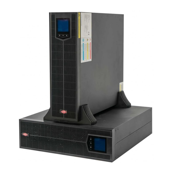
Page 14: Appearance
2 Overview ECO energy conservation mode design The UPS is designed with ECO energy conservation mode. When the grid is good, if the UPS operating in this mode, the bypass prior to output, and the efficiency can be 99%.When the bypass voltage or frequency out of normal range and cannot satisfy the user’s power supply requirement, it will switch to inverter output, which guarantee the reliability of power supply and also, save energy. - Page 15 2 Overview Operation panel Figure2-2 Operation panel Table2-1 Illustration for operation panel Name Illustration Illustration for operation panel ○ LCD display Shows the working status and system setting. " "page up Short press " " button, the LCD will enter previous page or ○...
- Page 16 2 Overview Name Illustration and the corresponding indicate LED is on. Rear panel 10kVA-20kVA Figure2-3 Rear panel of 10kVA-20kVA The wiring terminal of 33 mode and 31 mode have a little different. For the detail of the wiring terminal of each mode please see 3.4.1 Wiring Operation. The intelligent slot is optional: Built-in SNMP card, RS485+dry contact card and communication protocol transfer card.
-
Page 17: Fittings Illustration
2 Overview The intelligent slot is optional: Built-in SNMP card, RS485+dry contact card and communication protocol transfer card. If the BMD and EPO detection function won't be used, please short the port by equipped 4P terminal. When the function needs to be used, dismantle the short wire of BMD or EPO port and connect it with corresponding status signal input of maintenance bypass breaker or EPO. - Page 18 2 Overview Copper bar No. Illustration Sketch map 3PIN copper bar 3PIN copper bar The installation position of the UPS main and power distribution module is as shown inFigure2-5, Figure2-6. Figure2-5 Installation 33 mode copper bar position of 10kVA-20kVA UPS Figure2-6 Installation31 mode copper bar position of 10kVA-20kVA UPS...
- Page 19 2 Overview 30kVA-40kVA (30kVA-40kVA) UPS and distribution module has 2 kinds of copper bar, as shown inTable2-3. Connect the wiring terminal of the UPS or distribution module with the copper bar according to needs. The copper bar for short connect with the three phase bypass input terminal and three phase output terminal only for 31 mode UPS.
-
Page 20: Work Principle
2 Overview Figure2-8 Copper bar 2# installation position of 31 mode power distribution module 2.2 Work Principle 2.2.1 Work Principle Diagram Work principle diagram of the UPS is as shown in Figure2-9. Figure2-9 Work principle diagram The UPS includes rectification/PFC, inverter, charger, bypass static switch etc function module, the input power includes mains input, bypass input, battery input, the output mode includes inverter output, bypass output and maintenance bypass output (if equipped). -
Page 21: Work Mode
2 Overview and output pure sine-wave AC power, the output turns to inverter output to load from bypass output (if equipped). When mains abnormal, the battery voltage boosts by rectification/PFC and output DC bus voltage, and then go through inverter and output pure sine-wave AC power to load. When mains recover normal, the UPS turns to mains mode from battery mode automatically. - Page 22 2 Overview Figure2-11 Battery inverter mode (the thick solid line stands for the energy flow direction) Before the battery stop discharging, if the mains recover normal, the rectifier will transfer to mains input automatically and charge the battery at the same time. That is to say, the UPS recover normal mains power supply mode.
- Page 23 2 Overview Figure2-12 Bypass power supply mode (the thick solid line stands for the energy flow direction) ECO power supply mode (just suitable for single UPS) At the ECO mode, when bypass voltage normal, the power for load is prior supplied by bypass, when bypass voltage abnormal, the power for load turns to inverter.
-
Page 24: Optionals
2 Overview Figure2-13 Maintenance bypass power supply mode (the thick solid line stands for the energy flow direction) 2.3 Optionals UPS can equip distribution module or battery box according to needs. 2.3.1 Distribution Module Appearance Figure2-14 Appearance of distribution module Front panel of 10kVA-20kVA The operation breakers of distribution module locate inside the front panel, when operating, it needs to open the front panel fist. - Page 25 2 Overview Figure2-15 Open the front panel of 10kVA -20kVA UPS When install the front panel, insert the buttons at right side into the body, and then insert the buttons at left side into the body. Figure2-16 Distribution module illustration (dismantle front panel) of 10kVA -20kVA UPS Rear panel of 10kVA-20kVA Figure2-17 Distribution module illustration (dismantle front panel) of 10kVA -20kVA UPS...
- Page 26 2 Overview Front panel of 30kVA-40kVA The operation breakers of distribution module locate inside the front panel, when operating, it needs to dismantle the front panel fist. Open the front panel way as shown in Figure2-18. Figure2-18 Open the front panel of 30kVA -40kVA UPS When install the front panel, insert the buttons at right side into the body, and then insert the buttons at left side into the body.
-
Page 27: Battery Box
2 Overview Rear panel of 30kVA-40kVA Figure2-20 Distribution module rear panel of 30kVA -40kVA UPS 2.3.2 Battery Box Appearance Figure2-21 Appearance of battery box Rear panel Figure2-22 Rear panel of battery box... -
Page 28: Installation
3 Installation 3 Installation This chapter mainly introduces the installation of the UPS, including unpacking and checking, cable selection, installation, electrical connection, etc. 3.1 Unpacking and Checking Unpack and check the UPS according to follows. Inspect the appearance for shipping damage. If any shipping damage is found, report it to the carrier immediately. -
Page 29: Selectbreaker&Wires
3 Installation Tools 3.2.2 Select Breaker&Wires The selecting for AC input and output wire, DC input wire and corresponding breakers needs to be judged by the UPS' max. steady state phase current. Table3-1 shows the max. steady state phase current of each work mode, Table3-2 shows the rated current of recommended breakers, Table3-3 shows the min. -
Page 30: Select Input Breaker
3 Installation type 10kVA 15kVA 20kVA 30kVA 40kVA Mode type Bypass input DC input(A) AC output (A) 3.2.3 Select Input Breaker We suggest to add a breaker (we suggest to select the breaker with feedback double pole disconnection equipment) or distribution cabinet that matches the UPS power at the front of the UPS input to insulate the mains. -
Page 31: Select Wires
3 Installation 3.2.4 Select Wires For the wire cross-sectional area of AC input, output and battery please see the recommended value in Table3-3 Table3-4 and Table3-5. The cross-sectional area of the following cable is only for reference when the user is connected wire for a length of about 5 meters. - Page 32 3 Installation Table3-4 Recommended cross-sectional area of wire (unit: mm , environment temperature: 25℃) type 30kVA 40kVA Mode type 33 mode 31 mode 33 mode 31 mode AC input live wire (U/V/W) 16*3 16*3 16*3 16*3 16*2 AC input neutral wire (N) 16*1 16*1 25*2 (parallel)
- Page 33 3 Installation Figure3-1 Wiring terminal dimensions of 10 kVA-20kVA UPS Table3-6 Dimensions limit of wiring terminal Dimensions 10kVA 15kVA 20kVA (unit: mm) ≤12.1 ≤12.1 ≤12.1 ≥6.2 ≥6.2 ≥6.2 ≤6.2 ≤6.2 ≤6.2 ≤6.2 ≤6.7 ≤7.2 ≤6.7 ≤7.2 ≤9.0 ≤7.2 ≤9.0 30kVA-40kVA UPS Wiring terminal dimensions of the wiring terminals of 30kVA-40kVA UPS recommend type as shown in Figure3-2.
-
Page 34: Mechanical Installation
3 Installation Dimensions (unit: mm) 30kVA 40kVA ≤24 ≤24 ≤24 ≤29.4 4.7±0.3 5.83±0.3 5.83±0.3 7.43±0.3 When the 30kVA-40kVA UPS is set to 31mode, the terminal (as shown in Figure3-3) will be used, and it size requirements are shown in Table3-8. Figure3-3 Wiring terminal dimensions Table3-8 Dimensions limit of wiring terminal Mode... -
Page 35: Tower-Mounting
3 Installation 3.3.1 Tower-mounting Single UPS installation Step 1 Take out a pair of support base and 1U joint base, assemble them together, as shown in Figure3-4, and lay them flat for the UPS tower base. Figure3-4 Assemble support base Step 2 Put the UPS onto the assembled support base, as shown in Figure3-5. - Page 36 3 Installation Figure3-6 Assemble support base When one optional added, 3 pieces of 1U joint base need to add, the assemble way is the same. Put the UPS and distribution module onto the assembled support base, as shown in Step 2 Figure3-7.
-
Page 37: Rack-Mounting
3 Installation Figure3-8 Install combination units Every two adjacent devices need to be connected by two combination parts at the top of the device, that is to say, every add one optional (distribution module or battery box), it needs to install another 2 combination parts. - Page 38 3 Installation Figure3-9 Install angle iron Do not transport the UPS, battery box or power distribution module by angle iron. The front panel can be dismantled front, during transporting, do not make it bear any force. The device needs to be transported by two or more people. Step 2 Push the UPS into the cabinet, and fasten it by screws, as shown in Figure3-10.
-
Page 39: Electrical Connection
3 Installation 3.4 Electrical Connection Before connecting, ensure that the external connected front breakers of mains, battery are all off. DO NOT connect wires with electricity. While wiring, avoid making the power wire at the place where is easy to be trod or tripped. If there is an optional distribution module, the wiring of UPS and distribution module (optional) shall be connected with the distribution module wire first, and then the UPS wire. -
Page 40: Wiring Operation Of 30Kva-40Kva Ups
3 Installation 31 mode The input and output wiring of 33mode UPS is as shown in Figure3-12. Figure3-12 The 31 mode wiring of 10kVA-20kVA UPS 3.4.2 Wiring Operation of 30kVA-40kVA UPS 33 mode The input and output wiring of 33mode UPS is as shown in Figure3-13. The output and input have two N-terminal bar respectively, and they separate parallel connection. - Page 41 3 Installation Figure3-13 The 33 mode wiring of 30kVA-40kVA UPS 31 mode Take out a couple of copper bar 1#, connect them to the wiring terminal of UPS. The wiring diagram of 31 mode UPS is as shown inFigure3-14.When the wire output and the input N wire are in parallel of two cables, the two groups of N-terminals are connected separately.
-
Page 42: Wiring Between Ups And Battery Box
3 Installation 3.4.3 Wiring Between UPS and Battery Box DC battery switch must be provided between the battery and UPS. User can select tower-mounting or rack-mounting the UPS according to use space. Specific installation requirements are as follows: Rack-mounting products: UPS installed in the bottom layer, distribution module installed in the top layer for easy cable connection and operation. - Page 43 3 Installation Figure3-16 Wiring diagram between UPS and two parallel connected battery boxes Figure3-17 Wiring diagram between UPS and two sets parallel connected battery boxes (each set has two battery boxes)
-
Page 44: Wiring Between Ups And Battery Box Of 30Kva-40Kva Ups
3 Installation The wiring between UPS and parallel connected battery boxes must be connected strictly according to Figure3-16, Figure3-17, avoid wrong connection or short circuit. 3.4.5 Wiring Between UPS and Battery Box of 30kVA-40kVA UPS The wiring of parallel connected battery box and each mode UPS is the same, in this section, we take 40kVA as an example to illustrate. -
Page 45: Wiring Between Ups And Distribution Module Of 10Kva-20Kva Ups
3 Installation Wiring of external batteries If user needs to connect batteries externally, please connect the wires as follows. This series UPS's battery input adapt positive and negative battery group (each battery group default has 16 positive cell and 16 negative cell). Figure3-19 shows one wiring way: one battery cabinet has 32 cells and one 3P breaker, the external wiring includes BATT.+, BATT.- and battery neutral wire. - Page 46 3 Installation Figure3-20 Wiring Between 33 mode UPS and Distribution Module of 10kVA-20kVA UPS 31 mode The copper bar from Table2-2 are short connect with 3P terminal bar of the bypass and output. The supporting UPS and the distribution wire are connected one to one according to the wire information.
-
Page 47: Wiring Between Ups And Distribution Module Of 30Kva-40Kva Ups
3 Installation Ensure that the wires are connected properly and firmly, and then install the wiring protection plate to the device (the installation procedure is as follows). 3.4.7 Wiring Between UPS and Distribution Module of 30kVA-40kVA UPS Wiring of each standard UPS and distribution module is shown in Figure3-22andFigure3-23. 33 mode The supporting UPS and the distribution wire are connected one to one according to the wire information. - Page 48 3 Installation Figure3-23 Wiring Between 31 mode UPS and Distribution Module of 30kVA-40kVA UPS Ensure that the wires are connected properly and firmly, and then install the wiring protection plate to the device (the installation procedure is as follows). Install wiring plates The wiring covers' install procedure of each mode UPS and distribution module is the same, in this section, we take 40kVA as an example to illustrate.
- Page 49 3 Installation Remove the protective cover, as shown inFigure3-25. Step 2 Figure3-25 Remove the protective cover Step 3 Connect the wires in accordance with3.4.1 Wiring Operation as shown in Figure3-26. Figure3-26 Connect the wires Step 4 Reinstall the wiring row cover in the corresponding position of the chassis, as shown in Figure3-27.
-
Page 50: Wiring Of Parallel System
3 Installation Fix with the flat head screws, as shown in Figure3-28. Step 5 Figure3-28 Fix with the flat head screws ----End 3.4.8 Wiring of Parallel System Step 1 Install the battery and UPS of parallel system separately according to 3.3 Mechanical Installation. - Page 51 3 Installation Figure3-29 Diagram of 33 mode parallel system wiring of 10kVA-20kVA UPS...
- Page 52 3 Installation Figure3-30 Diagram of 31 mode parallel system wiring of 10kVA-20kVA UPS 30kVA-40kVA...
- Page 53 3 Installation Figure3-31 Diagram of 33 mode parallel system wiring of 30kVA-40kVA UPS...
- Page 54 3 Installation Figure3-32 Diagram of 31 mode parallel system wiring of 30kVA-40kVA UPS Step 3 Connect the parallel port of each unit in parallel by parallel wires, as shown in Figure3-33. Figure3-33 Wiring diagram of parallel wire...
- Page 55 3 Installation The wiring of parallel port of each mode UPS is the same, in above figure, we take 30kVA as an example to illustrate. The UPS parallel system requires the user to distribute power by himself. The wiring and phase sequence of each unit in the parallel system must be the same strictly, which is to ensure the bypass power of parallel system is the same phase.
-
Page 56: Screen Operation
4 Screen Operation 4 Screen Operation This chapter mainly introduces the working parameters, working status and system settings of UPS screen. 4.1 Menu Hierarchy The menu hierarchy of the screen is as shown in Figure4-1. Figure4-1 Menu hierarchy of the screen The parameter values and other details in the pictures in this chapter are for illustration only. -
Page 57: Power On For The First Time
4 Screen Operation 4.2 Power On for The First time After power on, the system will enter the welcome page first. If the UPS is started for the first time, the welcome page will stay 5s after entering the password input page, as shown in Figure4-2. -
Page 58: System Working Status Display
4 Screen Operation Figure4-3 Main Page After entering the main interface, it is easy to monitor the system. The meaning of the icons on the main interface is as follows: :System bypass icon. :System rectification icon. :System inverter icon. :System battery icon. The internal energy bar of the battery changes accordingly depending on the current battery status and battery voltage. - Page 59 4 Screen Operation Figure4-4 Main power Inverter Output Figure4-5 Battery Inverter Output Figure4-6 ECO/Bypass output Figure4-7 Maintenance bypass output...
-
Page 60: Monitoring Page
4 Screen Operation 4.5 Monitoring Page After the system automatically enters the monitoring page, the monitoring page in the lower right corner has page number display, according to the current set of different system, the total number of monitoring pages displayed is different. By pressing the up/down page button, you can turn on the monitoring page, and the monitoring page loop display, three-in and three-out page number and page loop order as shown in Figure4-8. -
Page 61: Management Setting
4 Screen Operation Figure4-9 Setting page structure diagram 4.7 Management Setting In any monitoring page by long pressing function button for 3s can enter the settings management page, the page is mainly for the directory display function, the page display includes: parameter set, function set, log manage, screen set and permission set five items, as shown in Figure4-10. -
Page 62: Parameter Setting
4 Screen Operation management page and press the function button shortly, the display takes you to the previous page. 4.7.1 Parameter Setting In the settings management page, select the "Parameter Set" option, and short press the function button shortly to enter the parameter settings page, which is a second class page, mainly for the directory display function, the page display includes: bypass parameter settings, battery parameter settings and output parameter setting three, as shown in Figure4-11 and Figure4-12. -
Page 63: Function Setting
4 Screen Operation function button can go to the corresponding next level of settings page. When you select the back button at the lower right corner, the return button is displayed as opposite color state, and this time, short press function button can go to the previous level of the page, and the previews class parameter settings page is the settings management page. - Page 64 4 Screen Operation There are four next-level pages on the function set page, and the page display includes: mode set, ECO set, battery test and else set four items, as shown in Figure4-14. The following is to take the battery test page as an example, explain the three-level page setting method, the rest of the page setting method is the same, will not repeat the story.
-
Page 65: Screen Setting
4 Screen Operation Back-up time display settings: When there are other more accurate battery remaining discharge time monitoring devices in the system, you can choose to turn off the battery residual discharge time display function of the UPS itself. Call self-start setting: manual mode is that human shutdown needs to be re-manual power edged to trigger the UPS self-start function after the power generation, automatic mode is as long as the normal power generation UPS is self-starting, under this condition UPS shutdown can only be manually shut down when the battery is reversed, suitable for unattended applications. -
Page 66: Permission Setting
4 Screen Operation the day is flashing, short press function button to finish the date setting after adjusting the day number to the corresponding number. The time setting, language settings are the same as the date settings, and it will not be repeated here. - Page 67 4 Screen Operation Figure4-17 Permission setting page The permission set page includes trial function and trial time two setting items, and the trial time will not be displayed until the trial function is turned on. By pressing the up/down page button and working with the function button's short press operation, you can set the trial function and the trial time, the setting method is the same as the other settings mentioned above, and it is not repeated here.
-
Page 68: Use And Operation
5 Use and Operation 5 Use and Operation This chapter mainly describes the operation process, operation method, daily maintenance and troubleshooting, etc. 5.1 Check Before Startup Check if the wire connection is firm and the color of AC wires is in accordance with the specification. -
Page 69: Shutdown Operation
5 Use and Operation Start load according to "high power device→small power device", which is to avoid overload protection when starting high power device. ----End 5.3 Shutdown Operation Step 1 Close load and keep the UPS running without load for about10min to exhaust heat. Press "... -
Page 70: Shut Down Parallel System
5 Use and Operation lead to the inverter fault. If the circulating current larger than 3A, please report it to our company to maintain it. Switch on the total output breaker of output distribution cabinet, each output branch breaker, Step 3 and then start the load one by one. -
Page 71: Redundance Function Of Parallel System
5 Use and Operation Figure5-2 Add new UPS into parallel system 5.4.5 Redundance Function of Parallel System When system adopts N+1 redundance design, the total output cannot larger than N times of single unit's rated power. When one paralleled unit fault, it can put into use or exit parallel system and do not affect the operation of system, which enhance the system reliability. -
Page 72: Troubleshooting
5 Use and Operation Generally, charge and discharge the battery once every 4 to 6 months. Discharge the battery till under-voltage and power off and then charge it. In high temperature area, charge and discharge the battery once every 2 months. The charging time for the standard battery should be more than 10 hours every time. - Page 73 5 Use and Operation Fault phenomenon Possible reason 2. The load is not started according to "high power device → small power device". Restart the UPS, and after the UPS works steadily, start high power load first, and then start small power ones successively. 1.
- Page 74 5 Use and Operation fault Buzzer status Meaning symbol Err. actual wiring do not match the fault, please check the main power or bypass wiring, and make the actual system is consistent with the set mode system. UPS maintenance bypass protection, inverted Maintenance Long beep output closed,...
- Page 75 5 Use and Operation fault Buzzer status Meaning symbol Single Err. Slow beep Fall-off fault at one ends of the parallel wire. UPS internal working power failure, if it cannot be Long beep automatically recovered, please report repair promptly. Urgent beep Fan fault warning prompt, please check the fan Fan fault (alarm once...
- Page 76 5 Use and Operation fault Buzzer status Meaning symbol bypass phase sequence is normal, if the wiring way of bypass matches the system mode setting. Slow beep(alarm Battery has been pressure protection, charging once about every fuse failure, over-pressure alarm fault, please 2.0s) check the battery status is normal.
-
Page 77: Package, Transportation And Storage
6 Package, Transportation and Storage 6 Package, Transportation and Storage 6.1 Package During packing, please pay attention to the place direction requirements. At the side of the package, there is afraid of wet, handle with care, upward, stack layer limit, etc. alarm marks. And also, the device model is printed on the package. -
Page 78: A Technical Specifications
A Technical Specifications Technical Specifications Model 10kVA 15kVA 20kVA 30kVA 40kVA Index Input mode 3W+ N+PE(can be set as 1W+ N+PE) 3W+ N+PE When the input voltage in the range of 176~280, the UPS can bear load of 100% rated power; Voltage range (Vac) When the input voltage in the range of 80-176, the output of the UPS needs to... - Page 79 A Technical Specifications Model 10kVA 15kVA 20kVA 30kVA 40kVA Index ±144~±240 (can be selected from ±12 cells ~±20 cells, default is ±16 cells, when Battery the battery voltage is set from ±12 cells ~±15 cells, the output of the UPS voltage (Vdc) decreases to 75% rated) (single battery voltage is 12Vdc) Charge...
- Page 80 A Technical Specifications Model 10kVA 15kVA 20kVA 30kVA 40kVA Index 130%~150%: 1min >150%: 200ms Bypass: <130%: continue 130%~155%: 1min >155%: 200ms startup Equipped function Panel display LCD shows the running status of the UPS Communicati RS485 on port Alarm Alarm for battery low-voltage, mains abnormal, UPS fault, output overload, etc. function Protection Protection for battery under-voltage, overload, short-circuit, over-temperature,...
Need help?
Do you have a question about the IST9 and is the answer not in the manual?
Questions and answers