Table of Contents
Advertisement
Quick Links
Advertisement
Table of Contents
Troubleshooting

Related Manuals for AEC IST3-J 1 kVA


Summary of Contents for AEC IST3-J 1 kVA
- Page 1 UPS IST3-J (1-3kVA) Series User Manual...
- Page 3 Foreword Foreword Summaries Thank you for choosing UPS of AEC International! This document gives a description of the UPS, including the features, performance, appearance, structure, working principles, installation, operation, maintenance, transportation and storage, etc. Please save the manual after reading, in order to consult in the future.
- Page 4 UPS IST3-J (1-3kVA) User Manual Foreword Symbol Description Alerts you to a low risk hazard that could, if not avoided, result in minor injury. Anti-static prompting. Be care electric shock prompting. Provides a tip that may help you solve a problem or save time. Provides additional information to emphasize or supplement important points in the main text.
-
Page 5: Table Of Contents
UPS IST3-J (1K-3K) User Manual Contents Contents 1 Safety Description......................... 1 1.1 Safety Announcements ............................. 1 1.1.1 UPS Announcements..........................2 1.1.2 Battery Announcements .......................... 4 1.1.3 ESD Protection ............................4 1.1.4 Grounding Requirements ........................5 1.1.5 Measurement When Power On ....................... 5 1.2 Operation Announcements .......................... - Page 6 UPS IST3-J (1-3kVA) Contents User Manual 2.4.1 Battery Box ............................24 2.4.2 Programmable Outlets........................... 24 2.4.3 Charging Module (7A) .......................... 24 3 Installation............................ 25 3.1 Installation Announcements ........................... 25 3.2 Installation Preparation ..........................26 3.2.1 Installation Place and Environment Requirements ................26 3.2.2 Input Breaker Selection .........................
- Page 7 UPS IST3-J (1-3kVA) User Manual Contents 5.3.2 Battery Pack of UPS Replacement ......................42 5.3.3 Battery Pack of Battery Box Replacement .................... 44 5.4 Troubleshooting .............................. 48 6 Package, Transportation, Storage ..................... 52 6.1 Package ................................52 6.2 Transportation ..............................52 6.3 Storage ................................
-
Page 8: Safety Description
UPS IST3-J (1-3kVA) User Manual 1 Safety Description 1 Safety Description This chapter mainly describes safety announcements. Prior to performing any work on device, please read user manual carefully, follow operation and installation instructions and observe all danger, warning and safety information, which is to avoid human injury and device damage by irregular operations. -
Page 9: Ups Announcements
UPS IST3-J (1-3kVA) 1 Safety Description User Manual 1.1.1 UPS Announcements The input voltage and output voltage of device are dangerous high voltage. Touching high voltage will endanger human life. Before attempting to install or operate device, carefully read this manual and pay attention to all warning signs in the device. - Page 10 UPS IST3-J (1-3kVA) User Manual 1 Safety Description Don't connect ground wire and neutral wire, live wire and neutral wire reversely to avoid short circuit. Device should be grounded well and the voltage between ground wire and neutral wire should be less than 5V.
-
Page 11: Battery Announcements
UPS IST3-J (1-3kVA) 1 Safety Description User Manual 1.1.2 Battery Announcements It should use specified battery! Non-specified battery will damage UPS. The required charging voltage of different brands and different types of battery are different. Before using battery, ensure that the charging voltage of UPS is suitable for battery. If any doubt, please consult manufacturer for support. -
Page 12: Grounding Requirements
UPS IST3-J (1-3kVA) User Manual 1 Safety Description 1.1.4 Grounding Requirements High leakage risk! Before performing electrical connection, device must be grounded. The grounding terminal must be connected to ground. When installing device, it must be grounded first. When dismantling device, the grounding wire must be dismantled at last. - Page 13 UPS IST3-J (1-3kVA) 1 Safety Description User Manual The operation and wiring for UPS should be performed by qualified person, which is to ensure that the electrical connection meets the related standards. The installer should be trained strictly, know all kinds of safety announcements and get right operation methods before performing installation, operation or maintenance.
-
Page 14: Operation Environment Requirements
UPS IST3-J (1-3kVA) User Manual 1 Safety Description High leakage risk! Before performing electrical connection, device must be grounded. The grounding terminal must be connected to ground. Don't drill holes in the device! Inappropriate drilling will damage components inside device. Metal debris generated by drilling entering device will lead to circuit board short circuit. -
Page 15: Overview
They are widely applied to the many key business areas, such as post, finance, network, stock, railway, etc. The AEC IST3-J series (1K-3K) UPS are with the single-phase AC input and single-phase AC output. 2.1.1 Model Meaning □□□□... -
Page 16: Appearance
UPS IST3-J (1-3kVA) User Manual 2 Overview the computer, perform ON/OFF operation remotely and support SNMP network adaptor (external, connect with UPS through RS232 port), which makes UPS be a network new member. High input power factor Adopt the advanced active PFC technology, which eases load in the power grid. It is the new generation green power. -
Page 17: Operation Panel
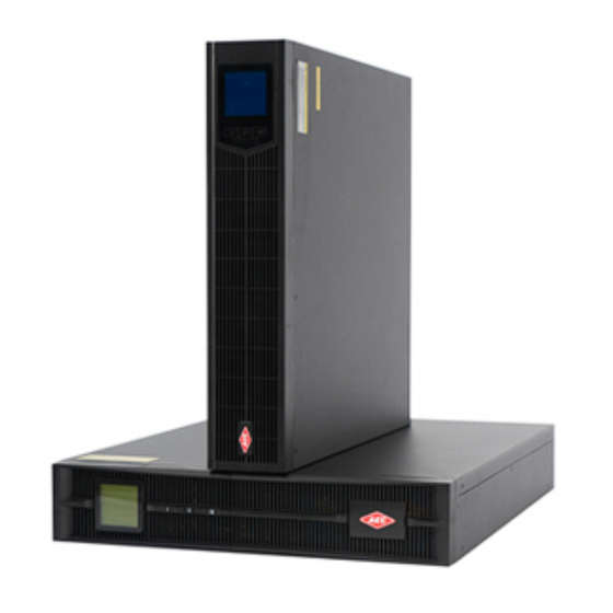
UPS IST3-J (1-3kVA) 2 Overview User Manual Figure2-3 Appearance of IST3-J 2kVA/ IST3-J 3kVA 2.2.1 Operation Panel Figure2-4 Operation panel of AEC IST3-J series (1K-3K) UPS Table2-1 The illustration of operation panel Icon Name Illustration ○ ,1 - Display the working status and setting of UPS. - Page 18 UPS IST3-J (1-3kVA) User Manual 2 Overview Icon Name Illustration Press " " button to transfer the display information, such as output voltage, output frequency, input voltage, input frequency, battery voltage, inner temperature, load percentage, fault information, etc. Press and hold " " button for 5s to enter the set page. ...
-
Page 19: Rear Panel View
UPS IST3-J (1-3kVA) 2 Overview User Manual Table2-2 The illustration of LCD panel Icon Illustration It shows input voltage, input frequency, output voltage, output frequency, load percent, temperature, fault code, parameters or working mode, etc. UPS works in the mains mode UPS works in the bypass mode UPS works in the battery mode UPS works in the ECO mode... - Page 20 UPS IST3-J (1-3kVA) User Manual 2 Overview IEC type (six IEC outlets) Figure2-8 Rear panel of IST3-J 1kVA Figure2-9 Rear panel of IST3-J 2kVA / IST3-J 3kVA Schuko type Figure2-10 Rear panel of IST3-J 1kVA Figure2-11 Rear panel of IST3-J 2kVA / IST3-J 3kVA UK type Figure2-12 Rear panel of IST3-J 1kVA...
- Page 21 UPS IST3-J (1-3kVA) 2 Overview User Manual Figure2-13 Rear panel of IST3-J 2kVA / IST3-J 3kVA Universal type Figure2-14 Rear panel of IST3-J 1kVA Figure2-15 Rear panel of IST3-J 2kVA/ IST3-J 3kVA Table2-3 The illustration of real panel Illustration Output outlet ○...
-
Page 22: Intelligent Slot
UPS IST3-J (1-3kVA) User Manual 2 Overview Illustration ○ RS232 communication port Intelligent slot ○ Standard: USB. Optional: RS485+dry contact, protocol transfer card, SNMP card, and cover. ○ Battery grounding port ○ ,10 Battery input ○ ,11 Battery breaker 2.2.3 Intelligent Slot RS485 and dry contact(optional) The pin sequence and pin definition of RS485 and dry contact is as shown in Figure2-16 and... - Page 23 UPS IST3-J (1-3kVA) 2 Overview User Manual The illustration of dry contact is as below: CN1, CN2, CN3 determine that dry contact output signal is normal open or normal close. In default, dry contact output signal is normal close, that is PIN1 connects with PIN2. If one route signal needs to set to normal open, connect PIN2 with PIN3.
- Page 24 UPS IST3-J (1-3kVA) User Manual 2 Overview Figure2-19 SNMP card Table2-5 The illustration of SNMP card Name Remark NETWORK port adopts RJ45 plug. The pin definition of the NETWORK port NETWORK port is shown in Figure2-20. COM1 port Connect with humiture module(RS485) Indicator Show working status 1--8...
-
Page 25: Epo Connector
5 (grounding end) 2.3 Working Principles When the mains is normal, the input of AEC IST3-J series (1K-3K) UPS converts into the ±360V steady DC voltage through PFC, which supplies power for DC/AC inverter to output steady 220V AC and charges battery at the same time. When the mains is abnormal, the battery will boost into the ±... -
Page 26: Fault Status
UPS IST3-J (1-3kVA) User Manual 2 Overview Mains Transfer PFC AC/DC DC/AC Load 220Vac switch DC/DC Charger Battery Figure2-21 Working principle 2.3.1 Fault Status UPS faults include: EPO protection, busbar voltage fault, IGBT over-temperature fault, fan fault (including fan blocked, fan damage, etc.) , output fault (including output overload protection, output short-circuit, etc.) , battery fault (including battery over-voltage protection, battery under-voltage protection, etc.) , etc. -
Page 27: Ups Parameters Setting (Lcd)
UPS IST3-J (1-3kVA) 2 Overview User Manual Figure2-24 IGBT over-temperature fault Figure2-25 Fan fault Figure2-26 Output fault Figure2-27 Battery fault 2.3.2 UPS Parameters Setting (LCD) Press and hold " " button for 5s to enter the set page. Then press " " button to transfer the setting information, such as ECO/INV mode, TWR/RCK (TWR: tower-mounting;... - Page 28 UPS IST3-J (1-3kVA) User Manual 2 Overview mode(the default setting is RCK mode) , the charging current that is 1A/2A/3A/4A/5A/6A/7A/8A (the default setting is 1A) or the inverting output voltage that is 208V/220V/230V/240V (the default setting is 220V) and press " "...
- Page 29 UPS IST3-J (1-3kVA) 2 Overview User Manual more than 1s to quit the set page, the setting is successful. In the RCK mode, the LCD display is as shown Figure2-30. Figure2-30 RCK mode TWR mode When LCD displays RCK mode and it has to set to TWR mode, in the set page, three characters "TWR"...
-
Page 30: Ups Parameters Setting (Pc)
Set the converter mode to enable or disable (default) . If the converter mode is enable, set the output frequency to 50Hz or 60Hz. 2.4 Optional Component AEC IST3-J series (1K-3K) UPS can be optionally equipped with battery box & programmable outlets & charging module as required. -
Page 31: Battery Box
2.4.3 Charging Module (7A) AEC IST3-J series (1K-3K) UPS can be equipped with a charging module with 7A to enhance the charging capacity of UPS, which can match battery with different amperages to ensure fast charging and prolong battery service life. -
Page 32: Installation
3.1 Installation Announcements As the AEC IST3-J series (1K-3K) UPS is small, it can put UPS on the flat surface directly without other fixed or installation. Keep a clearance at least 300mm~500mm around UPS and 500mm on the top of UPS, which is good for operation or maintenance or heat dissipation. -
Page 33: Installation Preparation
UPS IST3-J (1-3kVA) 3 Installation User Manual Figure3-1 Installation announcements 3.2 Installation Preparation 3.2.1 Installation Place and Environment Requirements Before attempting to install UPS, the installation place and environment should meet the basic condition for safety and normal running. If not, please do the corresponding change. If the basic conditions are all met, install UPS. -
Page 34: Input Breaker Selection
Besides, the selected breaker should be without the power leakage protection to avoid mis-operation. The distribution box is better to be made by the professional company. The selection of input breaker refers to Table3-1. Table3-1 The recommended input breaker of AEC IST3-J series (1K-3K) UPS IST3-J 1kVA IST3-J 2kVA... -
Page 35: Selection Of The Cross-Sectional Area Of Wire
3.2.3 Selection of the Cross-sectional Area of Wire For the selection of the cross-sectional area of AC input wire, AC output wire and battery wire of AEC IST3-J series (1K-3K) UPS, please refer to Table3-2 for the corresponding recommended value. -
Page 36: Installation Procedures
UPS IST3-J (1-3kVA) User Manual 3 Installation Inspect the appearance for shipping damage. If any shipping damage is found, report it to the carrier immediately. Check the delivery list to see if the types of accessories are complete and correct. If there is any discrepancy, contact the distributor immediately. - Page 37 UPS IST3-J (1-3kVA) 3 Installation User Manual Step 4 Fix UPS on the rack. ----End Battery box (optional) installation When the battery box is selected, the installation procedures are the same. In this section, we take the one battery box as an example. Step 1 Install the left and right plastic panel.
- Page 38 UPS IST3-J (1-3kVA) User Manual 3 Installation Step 2 Install two angle irons on battery box. Step 3 Fix battery box (optional) on the rack.
-
Page 39: Tower-Mounting
UPS IST3-J (1-3kVA) 3 Installation User Manual 3.4.2 Tower-mounting UPS Installation Step 1 Keep UPS upright, the side with battery should be up. Step 2 Install support bases together. Step 3 Fix the support bases on UPS. - Page 40 UPS IST3-J (1-3kVA) User Manual 3 Installation Step 4 Place UPS with support bases, and then install the plastic panel. Step 5 Set the display ways as tower-mounting, the detail refers to 2.2.1 . ----End Battery box (optional) installation When the battery box is selected, the installation procedures are the same. In this section, we take the one battery box as an example.
-
Page 41: Intelligent Slot Replacement
UPS IST3-J (1-3kVA) 3 Installation User Manual Step 2 Take out support bases and two 1U joint bases, assemble them together. When one battery box added, add 2 pieces of 1U joint bases, the assemble way is the same. Step 3 Put the UPS and battery box onto the assembled support bases. - Page 42 UPS IST3-J (1-3kVA) User Manual 3 Installation Step 2 Install optional intelligent slot and fix it. Step 3 Connect the communication cable. ----End...
-
Page 43: Electrical Connection
UPS IST3-J (1-3kVA) 3 Installation User Manual 3.5 Electrical Connection Figure3-2 Wiring diagram of IST3-J 1kVA Figure3-3 Wiring diagram of IST3-J 2kVA/IST3-J 3kVA Mains outlet should be installed near UPS and it is convenient to operate. Generally, the load current of each output outlet with 10A should be not more than 5A. 3.6 Check the Installation Table3-3 Installation checking Check items... - Page 44 UPS IST3-J (1-3kVA) User Manual 3 Installation Check items Result Check the AC output wire: whether the color of AC output wire is in accordance with the specification, whether the cross-sectional area of AC Yes□No□ output wire is suitable, whether the connection of the live wire(L), the neutral wire(N), the grounding wire(PE) is correct, whether the AC output wire is connected firmly.
-
Page 45: Operation Guide
UPS IST3-J (1-3kVA) 4 Operation Guide User Manual 4 Operation Guide This chapter mainly describes the checking before startup, startup and shutdown operation, etc. 4.1 Checking Before Startup Before using UPS, check the following items to ensure that UPS works normally. ... -
Page 46: Shutdown Operation
UPS IST3-J (1-3kVA) User Manual 4 Operation Guide 4.3 Shutdown Operation Step 1 Close load and keep UPS running without load for about10 minutes to exhaust heat. Step 2 Press " " button on the panel for 1s to shut down UPS. Step 3 Unplug mains outlet. -
Page 47: Maintenance And Troubleshooting
UPS IST3-J (1-3kVA) 5 Maintenance and Troubleshooting User Manual 5 Maintenance and Troubleshooting This chapter mainly describes maintenance guide, daily battery maintenance, battery replacement and troubleshooting. 5.1 Maintenance Guide Proper maintenance is the key that the device works on the best status and with a longer service life. 5.1.1 Safety Precautions To ensure human safety and device security, observe the following precautions. -
Page 48: Daily Battery Maintenance
UPS IST3-J (1-3kVA) User Manual 5 Maintenance and Troubleshooting 5.2 Daily Battery Maintenance Charging requirements of battery. When using battery for the first time, start UPS to charge battery for ten hours. During − charging, you still can use UPS. If UPS and battery are power down simultaneously, the discharging time of battery may be lower than standard this time. -
Page 49: Battery Pack Of Ups Replacement
UPS IST3-J (1-3kVA) 5 Maintenance and Troubleshooting User Manual A new battery should be with the same capacity, model, and manufacturer as the replaced one. Check whether there exists dangerous voltage between battery terminals and ground before touching, which is to avoid human injury. It is prohibited to touch the battery’s two wire connectors or bare terminals for wiring simultaneously. - Page 50 UPS IST3-J (1-3kVA) User Manual 5 Maintenance and Troubleshooting Step 5 Push the new battery pack into UPS. Step 6 Plug the battery wire. Step 7 Install the battery plate. Step 8 Install the right plastic panel.
-
Page 51: Battery Pack Of Battery Box Replacement
UPS IST3-J (1-3kVA) 5 Maintenance and Troubleshooting User Manual Step 9 Finish battery pack installation. ----End 5.3.3 Battery Pack of Battery Box Replacement The battery pack of battery box replacement for IST3-J 1kVA, IST3-J 2kVA, IST3-J 3kVA UPS are similar, the following take the battery pack of battery box for IST3-J 1kVA for an example. The battery pack is hot-pluggable. - Page 52 UPS IST3-J (1-3kVA) User Manual 5 Maintenance and Troubleshooting Step 2 Dismantle the battery plate. Step 3 Unplug the battery wire. Step 4 Pull out the left and right battery pack.
- Page 53 UPS IST3-J (1-3kVA) 5 Maintenance and Troubleshooting User Manual Step 5 Push the left and right new battery pack into battery box. Step 6 Plug the battery wire.
- Page 54 UPS IST3-J (1-3kVA) User Manual 5 Maintenance and Troubleshooting Step 7 Install the battery plate. Step 8 Install the left and right plastic panel.
-
Page 55: Troubleshooting
UPS IST3-J (1-3kVA) 5 Maintenance and Troubleshooting User Manual ----End 5.4 Troubleshooting After starting UPS, if UPS works abnormally, please refer to Table5-1 to find possible reason. Meanwhile, check whether the fault is caused by external environment, such as temperature, humidity are not accordance with requirements or UPS is overload. - Page 56 UPS IST3-J (1-3kVA) User Manual 5 Maintenance and Troubleshooting Phenomenon Possible reasons UPS works in the battery inverting not expedite. status, and the buzzer beeps intermittently. After installing UPS, switch on The wiring for three phase of input is wrong, e.g. breaker or press "...
- Page 57 UPS IST3-J (1-3kVA) 5 Maintenance and Troubleshooting User Manual Phenomenon Possible reasons (1) Load overload or output short circuit, UPS will turn off automatically. Buzzer long beeps, fault indicator is (2) Drive or power transistor failure. on, inverter failure and UPS turns to bypass mode.
- Page 58 UPS IST3-J (1-3kVA) User Manual 5 Maintenance and Troubleshooting Fault symbol Buzzer status Meaning inverting output is closed. Please check if cooling fan damage and air vents blocked. Output fault, please check if output is Long beep short-circuit or the load is too large. Battery fault, battery voltage too low or too high Long beep protection.
-
Page 59: Package, Transportation, Storage
UPS IST3-J (1-3kVA) 6 Package, Transportation, Storage User Manual 6 Package, Transportation, Storage This chapter mainly describes the announcements about the package, transportation, storage. 6.1 Package The package of product is carton. When packing, pay attention to the placing direction requirements. On one side of the carton, it should print warning icons, including keep dry, handle with care, this end up, stacking layer limit, etc. -
Page 60: A Technical Specifications
UPS IST3-J (1-3kVA) User Manual A Technical Specifications Technical Specifications Model IST3-J 1kVA IST3-J 2kVA IST3-J 3kVA Index When the voltage range is 176Vac~295Vac, it can connect with more than 75% load; when the voltage range is 154Vac~176Vac, it can connect with Voltage range(V) 50~75% load;... - Page 61 UPS IST3-J (1-3kVA) A Technical Specifications User Manual Model IST3-J 1kVA IST3-J 2kVA IST3-J 3kVA Index 1050VA/945W<Load 2100VA/1890W<Load 3150VA/2835W<Load Low overload for 10min ≤1100VA/990W ≤2200VA/1980W ≤3300VA/2970W 1100VA/990W<Load 2200VA/1980W<Load 3300VA/2970W<Load Medium overload for 1min ≤1300VA/1170W ≤2600VA/2340W ≤3900VA/3510W 1300VA/1170W<Load 2600VA/2340W<Load 3900VA/3510W<Load High overload for ≤1500VA/1350W ≤3000VA/2700W ≤4500VA/4050W...
- Page 62 UPS IST3-J (1-3kVA) User Manual A Technical Specifications Model IST3-J 1kVA IST3-J 2kVA IST3-J 3kVA Index 2000m (When the altitude exceeds 2000m, it is necessary to decrease rated Altitude power to use.) AC distribution system TN distribution system Dimensions (mm) 438*420*87 438*570*87 (W*D*H)
-
Page 63: B Acronyms And Abbreviations
UPS IST3-J (1-3kVA) B Acronyms and Abbreviations User Manual Acronyms and Abbreviations Alternating Current Direct Current Energy Control Operation Emergency Power Off International Electrotechnical Commission Liquid Crystal Display Protective Earthing RS232 Recommend Standard232 RS485 Recommend Standard485 SNMP Simple Network Management Protocol Uninterruptible Power System Universal Serial Bus...
Need help?
Do you have a question about the IST3-J 1 kVA and is the answer not in the manual?
Questions and answers