Table of Contents
Advertisement
Quick Links
Advertisement
Table of Contents
Troubleshooting

Subscribe to Our Youtube Channel
Related Manuals for AEC IST7 Series


Summary of Contents for AEC IST7 Series
- Page 1 UPS IST7 (60-200kVA) Series User Manual www.aecups.com...
- Page 3 Notice The purchased products, services and features are stipulated by the contract made between the customer. All or part of the products, services and features described in this document may not be within the purchase scope or the usage scope. Unless otherwise specification in the contract, all statements, information, and recommendations in this document are provided “AS IS”...
- Page 4 Uninterruptible Power Supply IST7 Series Foreword (60K-200K) User Manual Foreword Summaries Thank you for choosing the UPS product! This document gives a description of the IST7- series (60K-200K) UPS, including the features, performance, appearance, structure, working principles, installation, operation and maintenance. etc.
- Page 5 Uninterruptible Power Supply IST7 Series (60K-200K) User Manual Foreword Symbol Description Anti-static prompting. Be care electric shock prompting. Provides a tip that may help you solve a problem or save time. Provides additional information to emphasize or supplement important points in the main text.
-
Page 6: Table Of Contents
UPS IST7 Series (60K-200K) Contents User Manual Contents 1 Safety Instructions ........................1 1.1 Safety Announcements ............................. 1 1.1.1 Safety Instructions ..........................1 1.1.2 Use Announcements for Battery ......................4 1.1.3 Anti-Static Protection ..........................4 1.1.4 Grounding Requirements ........................5 1.1.5 Safety Warning Label Setting ......................... - Page 7 UPS IST7 Series (60K-200K) User Manual Contents 2.4.4 Battery Temperature Compensation ...................... 30 2.4.5 Surge Protection Device ........................30 2.4.6 Battery Release Control Accessory ....................... 30 2.5 Alarm Function ............................... 30 3 Installation............................ 41 3.1 Installation Procedure ............................. 41 3.2 Installation Preparation ..........................42 3.2.1 Installation Tools ...........................
- Page 8 UPS IST7 Series (60K-200K) Contents User Manual 4.3 System Work Status Display .......................... 69 4.4 Buzzer Control Function ..........................74 4.5 Monitor Page ..............................74 4.5.1 Mains Input Information ........................74 4.5.2 Bypass Input Information ........................75 4.5.3 Battery Input Information ........................75 4.5.4 Rectifier Information..........................
- Page 9 UPS IST7 Series (60K-200K) User Manual Contents 5.2 Operation Procedure ............................90 5.3 UPS Start and Shutdown ..........................91 5.3.1 Check before Startup ..........................91 5.3.2 UPS Startup ............................91 5.3.3 UPS Shutdown ............................93 5.3.4 Switch to Bypass Mode Manually ......................94 5.3.5 Switch to Maintenance Bypass Mode From Inverter Output ..............
-
Page 10: Safety Instructions
UPS IST7 Series (60K-200K) User Manual 1 Safety Instructions 1 Safety Instructions This chapter introduces the safety announcements. Prior to performing any work on the UPS, please read the user manual carefully to avoid human injury and device damage by irregular operations. - Page 11 UPS IST7 Series (60K-200K) 1 Safety Instructions User Manual It is prohibited to touching any terminal or conductor that connected with grid circuit, or, it may cause deadly danger. The damaged device or device fault may cause electric shock or firing! ...
- Page 12 UPS IST7 Series (60K-200K) User Manual 1 Safety Instructions Please do not put finger or tool into rotating fans to avoid endanger the human safety or damage the device. In case of fire, please use dry power fire extinguisher. If using liquid fire extinguisher, it may cause electric shock.
-
Page 13: Use Announcements For Battery
UPS IST7 Series (60K-200K) 1 Safety Instructions User Manual 1.1.2 Use Announcements for Battery Please use specified battery. Non-specified battery will damage the UPS. The charging voltage of different brand and different model battery is different. Before using, ensure that the charging voltage of the UPS matches that of battery. If doubted, please consult the manufacturer for support. -
Page 14: Grounding Requirements
UPS IST7 Series (60K-200K) User Manual 1 Safety Instructions 1.1.4 Grounding Requirements High leakage risk! The device must be grounded before electrical connection. The grounding terminal must be connected to earth. When installing, connect the grounding wire first; when dismantling, the grounding wire must be removed at last. -
Page 15: Operation And Maintenance Requirements
UPS IST7 Series (60K-200K) 1 Safety Instructions User Manual 1.2 Operation and Maintenance Requirements There exists high temperature and high voltage inside the UPS. Please comply with the relevant safety regulations and operation procedures during installation, operation and maintenance to avoid human injury or device damage. -
Page 16: Environment Requirements
UPS IST7 Series (60K-200K) User Manual 1 Safety Instructions endangers human life. It is necessary to set the UPS aside for enough time (≥10 min) to release all charge before opening the UPS chassis. The battery cables are not isolated with AC input. There may exist dangerous voltage between battery terminal and grounding terminal. -
Page 17: Overview
UPS IST7 Series (60K-200K) 2 Overview User Manual 2 Overview This chapter mainly introduces the use scope, product feature, work principle and modes, appearance and layout, alarm list etc. of the UPS. 2.1 Product Introduction IST7- series product is the high-frequency online double-conversion UPS. It is the high performance sine-wave UPS that special designed for the network computer room, precision instrument, etc. - Page 18 UPS IST7 Series (60K-200K) User Manual 2 Overview Smart fan speed control The fan speed is adjusted automatically in accordance with the load status, which prolong fan life and reduce noise. ECO energy conservation mode design The UPS is designed with ECO energy conservation mode. When the user power grid is good, if the UPS operating in this mode, the bypass prior to output, and the efficiency can be 99%.When the bypass...
-
Page 19: Work Principle
UPS IST7 Series (60K-200K) 2 Overview User Manual 2.2 Work Principle 2.2.1 Work Principle Diagram Maintenance bypass Bypass input Bypass unit Output Mains input Battery input Power unit Figure2-2 Work principle diagram 2.2.2 Work Mode There are 4 work modes of the UPS: normal mains mode, battery mode, bypass mode and maintenance bypass mode. -
Page 20: Appearance And Structure
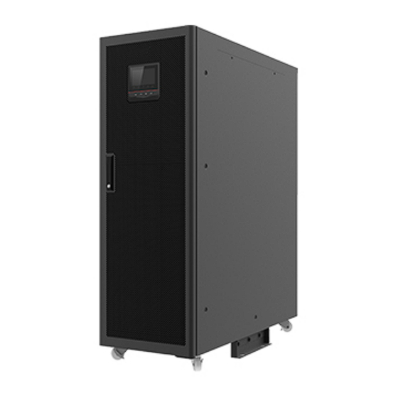
UPS IST7 Series (60K-200K) User Manual 2 Overview the same time. During the switch between grid power supply and battery power supply, the inverter output cannot power down. In battery power supply mode, if mains does not recover normal all the time, and the battery energy is running out, the UPS will send sound &... - Page 21 UPS IST7 Series (60K-200K) 2 Overview User Manual Figure2-3 Appearance of IST7-60, IST7-100, IST7-120 Figure2-4 Appearance of IST7-160, IST7-200...
- Page 22 UPS IST7 Series (60K-200K) User Manual 2 Overview Operation panel Figure2-5 Operation panel of IST7-60, IST7-100, IST7-120 Figure2-6 Operation panel of IST7-160, IST7-200 Table2-1 Illustration for the operation panel Sill-screen Name Illustration Shows the running parameters (such as voltage, ○...
-
Page 23: Structure Layout
UPS IST7 Series (60K-200K) 2 Overview User Manual Sill-screen Name Illustration On (green): inverter works normally. ○ DC/AC indicator On (red): inverter abnormal. On (green): bypass output. ○ BYP. indicator On (red): bypass abnormal. On (green): battery mode. ○ BATT. LOW indicator On (red): battery is low-voltage. - Page 24 UPS IST7 Series (60K-200K) User Manual 2 Overview Figure2-7 Structure layout diagram of IST7-60, IST7-100, IST7-120(open the door) The specifications of main switch, output switch, bypass switch and maintenance bypass switch of IST7- 100, IST7-120, IST7-60 are different a bit. The above take IST7-60 as example to illustration, for details please see the actual product.
- Page 25 UPS IST7 Series (60K-200K) 2 Overview User Manual Table2-2 Structure illustration Name Name ○ ○ Power unit Output switch ○ ○ Bypass unit Bypass switch ○ ○ Mains switch SPD(optional) ○ ○ SPD switch(optional) Maintenance bypass switch Power unit Figure2-9 Power unit...
- Page 26 UPS IST7 Series (60K-200K) User Manual 2 Overview Bypass unit Figure2-10 Bypass unit Table2-4 Bypass unit illustration Name Illustration ○ BATT. start button Battery cool start function. ○ SNMP card slot Optional SNMP card, for details please see 2.4.1 SNMP Card and Its Software.
- Page 27 UPS IST7 Series (60K-200K) 2 Overview User Manual Name Illustration ALARM On: system control card have alarm signal. (yellow) FAULT On: system control card fault. (red) Normal close input port of external EPO. The signal is valid ○ EPO2 input dry contact when NC terminal and COM terminal disconnect.
- Page 28 UPS IST7 Series (60K-200K) User Manual 2 Overview UPS1 UPS2 UPSn …… Bypass unit Bypass unit Bypass unit Figure2-13 RS485 port wiring(Multiple UPSs) Wiring color in Figure2-12 and Figure2-13 just for display only, it cannot stands for the actual wire color, for specific color please see the actual wire.
- Page 29 UPS IST7 Series (60K-200K) 2 Overview User Manual Table2-5 Dry contact illustration Port Skill-screen Signal Function illustration When the NO and COM is short External EPO normal open port EPO1 circuit, the signal is effective. The Reinforced insulation ground signal is preset and isn't settable.
- Page 30 UPS IST7 Series (60K-200K) User Manual 2 Overview Port Skill-screen Signal Function illustration External switch normal open When the NO and COM is short input port circuit, the signal is effective. This IN.2 signal is settable, as shown in Reinforced insulation ground Table2-6.
- Page 31 UPS IST7 Series (60K-200K) 2 Overview User Manual Dry contact definition Remarks Maintenance bypass start Start maintenance bypass mark. The output port(OUT port) card can be defined(18 types dry contact definition as shown in the Table2- 7) according to user requirements.
-
Page 32: Optional Accessory
UPS IST7 Series (60K-200K) User Manual 2 Overview Dry contact definition Remarks When the UPS inverter is abnormal, and this dry Inverter abnormal contact is ON. When detect single bypass feedback, and this dry Single bypass feedback contact is ON. - Page 33 UPS IST7 Series (60K-200K) 2 Overview User Manual Figure2-16 SNMP card When the SNMP card is selected, the SNMP card will be installed on the bypass unit of UPS. Table2-8 Illustration of SNMP card Name Function description ○ NETWORK port Ethernet port ○...
- Page 34 UPS IST7 Series (60K-200K) User Manual 2 Overview Table2-9 Illustration of indicator of the SNMP card Green indicator (R) Status description Red indicator (E) Start Flicker Running OFF/ON Crash, keep final status NO alarm Flicker Alarm * means the indicator is in any status.
-
Page 35: Expansion Cards
UPS IST7 Series (60K-200K) 2 Overview User Manual Default user name is admin, corresponding password is KHadmin0592. User can scan the QR code or enter the URL through browser(PC mode)to get more product information. User manual Software WiseWay KC502 WiseClose... - Page 36 UPS IST7 Series (60K-200K) User Manual 2 Overview Table2-10 Illustration of the dry contact Port Mark Signal Illustration OUT.4 normal close output port When the signal is effective, COM OUT.4 Reinforced insulation ground and NO connect, and NC disconnects. This signal is settable.
- Page 37 UPS IST7 Series (60K-200K) 2 Overview User Manual When the dry contact expansion card is selected, the dry contact expansion card will installed on the bypass unit of UPS. Table2-11 Illustration of the BMS expansion card Port Mark Signal Illustration It is used to communicate with the Li- battery.
-
Page 38: Parallel/Bcs System Accessory
UPS IST7 Series (60K-200K) User Manual 2 Overview 2.4.3 Parallel/BCS System Accessory Parallel/BCS system accessory are for parallel/BCS ports connection between cabinets. When multi UPSs in parallel, connect the parallel port of each UPS by parallel wire. N UPSs require N parallel wires to ensure there are at least two parallel wires for a UPS, which will improve parallel reliability. -
Page 39: Battery Temperature Compensation
UPS IST7 Series (60K-200K) 2 Overview User Manual 2.4.4 Battery Temperature Compensation The battery temperature compensation is used to monitor the battery temperature to realize the battery charging and discharging temperature compensation. When the battery temperature compensation function is selected, it will be configured that one temperature control wire, one temperature control extension cord and one 2Pin green terminal. - Page 40 UPS IST7 Series (60K-200K) User Manual 2 Overview Table2-12 Abnormal status and alarm/protection function Fault Information Protect requirement Alarm requirement Mains abnormal Mains over-voltage Mains under-voltage Mains unbalance Mains over-frequency Buzzer slowly beeps, the " Mains under-frequency " AC/DC indicator on...
- Page 41 UPS IST7 Series (60K-200K) 2 Overview User Manual Fault Information Protect requirement Alarm requirement operation panel turns red, Bypass under-voltage and the bypass icon on the Bypass unbalance touch screen turns red, and the yellow atmosphere lamp Bypass over-frequency normal on.
- Page 42 UPS IST7 Series (60K-200K) User Manual 2 Overview Fault Information Protect requirement Alarm requirement lamp normal on. Buzzer long beeps, the " Low output PF " DC/AC indicator on the operation panel turns Inverter output is red, and the output icon on not allowed.
- Page 43 UPS IST7 Series (60K-200K) 2 Overview User Manual Fault Information Protect requirement Alarm requirement not allowed red atmosphere lamp normal Buzzer long beeps, and the Parallel system sovereignty fault None red atmosphere lamp normal Buzzer long beeps, the " " OVERLOAD...
- Page 44 UPS IST7 Series (60K-200K) User Manual 2 Overview Fault Information Protect requirement Alarm requirement red atmosphere lamp normal Rectifier abnormal self-locking None Inverter abnormal self-locking None Battery overload protection None Battery discharge protection end None UPS abnormal None Cabinet pre-alarm...
- Page 45 UPS IST7 Series (60K-200K) 2 Overview User Manual Fault Information Protect requirement Alarm requirement alarm the yellow atmosphere lamp Battery circuit disconnect None normal on. Auxiliary power abnormal None Setting parameters mismatched None Battery parameters mismatched None Unit number inconformity...
- Page 46 UPS IST7 Series (60K-200K) User Manual 2 Overview Fault Information Protect requirement Alarm requirement Key parameters mismatched Parallel address conflict Unit serial version inconformity Component failure Bypass 1 NTC failure Bypass 2 NTC failure Cabinet NTC failure Buzzer slowly beeps, and...
- Page 47 UPS IST7 Series (60K-200K) 2 Overview User Manual Fault Information Protect requirement Alarm requirement Display CAN inside cabinet abnormal Parallel sync CAN abnormal Parallel equalized-current CAN abnormal Inner SCI communication abnormal Smart mode alarm Start generator mode Generator charge disabled Only one BCS system has been detected.
- Page 48 UPS IST7 Series (60K-200K) User Manual 2 Overview Fault Information Protect requirement Alarm requirement " BAT indicator on the Battery grounding abnormal operation panel turns red, the battery icon on the touch screen turns red, and the Battery switch opened yellow atmosphere lamp normal on.
- Page 49 UPS IST7 Series (60K-200K) 2 Overview User Manual Fault Information Protect requirement Alarm requirement Buzzer slowly beeps, and the yellow atmosphere lamp SPD abnormal normal on. Offline Power unit 1 offline alarm None Buzzer slowly beeps. status Power unit 2 offline In the battery under-voltage protection, if the mains is normal, the UPS will restart and charge the battery group.
-
Page 50: Installation
UPS IST7 Series (60K-200K) User Manual 3 Installation 3 Installation This chapter mainly introduces the installation of the UPS, including unpacking and checking, installation procedure, installation preparation, mechanical installation and system checking and test, etc. The UPS should be installed by authorized person who is special trained and achieve the qualification of high-voltage and AC power. -
Page 51: Installation Preparation
UPS IST7 Series (60K-200K) 3 Installation User Manual 3.2 Installation Preparation 3.2.1 Installation Tools Tools... -
Page 52: Installation Environment
UPS IST7 Series (60K-200K) User Manual 3 Installation The installation tools should be with isolated operation, which is to avoid electric shock. 3.2.2 Installation Environment Do not install the UPS in the place where exceeds the provision of technology index (temperature: -5℃~40℃, relative humidity: 0%~95%). -
Page 53: Installation Space
UPS IST7 Series (60K-200K) 3 Installation User Manual The optimal operating temperature for batteries is 20~30°C. Operating at temperatures lower than 20°C will shorten the battery backup time, and operating at temperatures higher than 30°C will shorten the battery lifespan. -
Page 54: Selection For Input And Output Wires
UPS IST7 Series (60K-200K) User Manual 3 Installation Avoid any object block the ventilation hole on the front panel and rear panel, which is to keep good ventilation for the UPS, or, it may rise the inner temperature, even influence the UPS service time. - Page 55 UPS IST7 Series (60K-200K) 3 Installation User Manual Model IST7- IST7- IST7- IST7- IST7- Item Bypass input current (A) 90.9 Recommended wire sectional 35×1 70×1 70×1 120×1 70×2 U/V/W/N area (mm Terminal DT-35 DT-70 DT-70 DT-120 DT-70 Output current(A) 90.9...
-
Page 56: Transportation And Unpacking
UPS IST7 Series (60K-200K) User Manual 3 Installation Model IST7- IST7- IST7- IST7- IST7- Item Terminal DT-16 DT-35 DT-35 DT-70 DT-70 The wires prepared by our company have passed the GB or UL certification. The wires quality is excellent, and all meet the production compliance. The cross-sectional areas above are recommended for 5 meters long wires. -
Page 57: Unpacking
UPS IST7 Series (60K-200K) 3 Installation User Manual Figure3-5 Manual forklift When lifting, pay attention to the balance and stable of the UPS. During moving, keep the UPS vertical and do not put down or uplift suddenly. 3.3.2 Unpacking Step 1 Check if the package appearance is in good condition and if there is any damage caused by transportation. - Page 58 UPS IST7 Series (60K-200K) User Manual 3 Installation Loosen the six M8 hexagon bolts of supporting plate and UPS by wrench, then loosen the four M10 hexagon bolts of wooden bracket and supporting plate(as shown in Figure3-6). Remove the supporting plate after make the wheels of the UPS in contact with the wooden bracket(as shown in Figure3-7).
-
Page 59: Mechanical Installation
UPS IST7 Series (60K-200K) 3 Installation User Manual 3.4 Mechanical Installation 3.4.1 IST7-60, IST7-100, IST7-120 Step 1 Determine and plan the installation position according to the UPS size (as shown in Figure3-9) and installation clearance requirement (see 3.2.3 Installation Space). - Page 60 UPS IST7 Series (60K-200K) User Manual 3 Installation The recommended bolts is M10, corresponding drilling depth is 60mm, which can be adjusted according to the actual installation situation. If channel steel is used for installation, drill four installation holes φ14mm on the channel steel ...
-
Page 61: Ist7-160, Ist7-200
UPS IST7 Series (60K-200K) 3 Installation User Manual The exposed height of expansion bolt must be within 30mm to 50mm. Step 4 Fasten the supporting plate. Put the supporting plate on the ground where has been drill the expansion bolts. Install the flat gasket(Φ10), spring gasket(Φ10) and bolts(Φ10), then pre-screw the bolts, as shown in Figure3-13. - Page 62 UPS IST7 Series (60K-200K) User Manual 3 Installation When ground installation, please dug a trunking for the routing at installation site in advance, as shown in Figure3-15. Figure3-15 Trunking diagram The trunking of this series UPS is similar, the recommended size is A*W*H=210mm*450mm*100mm.
- Page 63 UPS IST7 Series (60K-200K) 3 Installation User Manual Figure3-17 Bottom installation size (bottom view of pedestal) The recommended bolts is M12, corresponding drilling depth is 75mm, which can be adjusted according to the actual installation situation. If channel steel is used for installation, drill four installation holes φ14mm on the channel steel ...
-
Page 64: Optional Accessory Installation
UPS IST7 Series (60K-200K) User Manual 3 Installation Figure3-19 Install expansion bolts The expansion tube shouldn’t be higher than the ground, which is to avoid affecting the installation. The exposed height of expansion bolt must be within 50mm. Step 4 Move the UPS from wooden bracket to the ground by forklift, and align the bottom installation hole with the expansion bolt, and screw the bolts. - Page 65 UPS IST7 Series (60K-200K) 3 Installation User Manual SNMP card Step 1 Dismantle the SNMP card cover plate on the bypass unit, as shown in Figure3-21. Figure3-21 Dismantle the SNMP card cover plate Step 2 Take the SNMP card and install it on the bypass unit by 2 bolts, as shown in Figure3-22.
-
Page 66: Battery Release Control Accessory Installation
UPS IST7 Series (60K-200K) User Manual 3 Installation Step 2 Take the expansion card and install it on the bypass unit, as shown in Figure3-24. Figure3-24 Install the expansion card ----End 3.4.4 Battery Release Control Accessory Installation Ensure that the UPS is completely shutdown before install the battery release control accessory. - Page 67 UPS IST7 Series (60K-200K) 3 Installation User Manual Figure3-26 Installation position of PCB for IST7-160, IST7-200 Step 2 Connect the CN1~CN5 on PCB to the UPS and bus bar of customer respectively, for the connection illustration of each terminal as shown in Figure3-27.
-
Page 68: Install Battery Cabinet
UPS IST7 Series (60K-200K) User Manual 3 Installation 3.4.5 Install Battery Cabinet Important safety rule Do not open or disassemble the battery, for the inner electrolyte is harmful for eyes. If contacting the electrolyte with careless, please wash the contact part with plenty water and go to hospital immediately. -
Page 69: Wiring
UPS IST7 Series (60K-200K) 3 Installation User Manual ----End After assembly and test, the UPS can put into use. 3.5 Wiring Recommend that add the contactor of 220V AC coil in AC side for reverse feedback protect device. 3.5.1 IST7-60, IST7-100, IST7-120 Step 1 Open the front door of the UPS, remove the front and rear wiring cover plate, as shown in Figure3-28. - Page 70 UPS IST7 Series (60K-200K) User Manual 3 Installation Figure3-29 Down wiring holes diagram of IST7-60, IST7-100, IST7-120 Figure3-30 Wiring terminal diagram of IST7-60, IST7-100, IST7-120 When mains and bypass in one source, the terminal bars of mains and bypass as the mains input, bypass wiring terminal preferred.
-
Page 71: Ist7-160, Ist7-200
UPS IST7 Series (60K-200K) 3 Installation User Manual IST7-60, IST7-100, IST7-120 equip the mains and bypass in one source. When customers need wiring that mains and bypass in different source, they need to remove the three copper bars (as shown in Figure3-31) that are short circuited the mains and bypass, and then connect the mains and the bypass respectively. - Page 72 UPS IST7 Series (60K-200K) User Manual 3 Installation Figure3-33 Remove the back and top wiring cover plate of IST7-160, IST7-200 Step 2 Lead the input cables, output cables, battery cables and PE go through the top wiring hole(the position of wire inlet and outlet holes as shown in Figure3-34), and connect the wiring terminal respectively(the wiring terminal as shown in Figure3-35, Figure3-36), then fasten the bolts.
- Page 73 UPS IST7 Series (60K-200K) 3 Installation User Manual Figure3-35 PE position of IST7-160, IST7-200 Figure3-36 Wiring terminals bars diagram of IST7-160, IST7-200...
- Page 74 UPS IST7 Series (60K-200K) User Manual 3 Installation When wiring, ensure that the connection between input/output wire and input/output terminal is reliably, avoid bad connection or wrongly connection. IST7-160, IST7-200 equip the mains and bypass in one source. When customers need wiring that mains and bypass in different source, they need to remove the three copper bars (as shown in Figure3-37) that are short circuited the mains and bypass, and then connect the mains and the bypass respectively.
-
Page 75: System Check And Test
UPS IST7 Series (60K-200K) 3 Installation User Manual ----End 3.6 System Check and Test 3.6.1 Check Electrical Connection After finishing the electrical connection, check the following items. Table3-2 Check list Check item Result Yes□ No□ Check if the color of AC cables is in accordance with the specification. -
Page 76: Touch Screen Operation And Setting
UPS IST7 Series (60K-200K) User Manual 4 Touch Screen Operation and Setting 4 Touch Screen Operation and Setting This chapter mainly introduces the work parameters and work status and system setting of the UPS. 4.1 LCD Interface Flowchart Mains input... -
Page 77: Main Page
UPS IST7 Series (60K-200K) 4 Touch Screen Operation and Setting User Manual The value in the figures of this chapter is just for illustration, for real interface please see the actual product. 4.2 Main Page After powering on, it will enter the main page, as shown in Figure4-2. -
Page 78: System Work Status Display
UPS IST7 Series (60K-200K) User Manual 4 Touch Screen Operation and Setting : Information record. : System parameter setting. : Login. : Buzzer control. : Alarm. : ON/OFF. The working status and energy flow on the main page shows the system running status and unit running condition directly. - Page 79 UPS IST7 Series (60K-200K) 4 Touch Screen Operation and Setting User Manual Figure4-4 Shutdown Figure4-5 Bypass output...
- Page 80 UPS IST7 Series (60K-200K) User Manual 4 Touch Screen Operation and Setting Figure4-6 Battery inverter output Figure4-7 Mains inverter output...
- Page 81 UPS IST7 Series (60K-200K) 4 Touch Screen Operation and Setting User Manual Figure4-8 Grid-tied self-load running Figure4-9 ECO bypass output...
- Page 82 UPS IST7 Series (60K-200K) User Manual 4 Touch Screen Operation and Setting Figure4-10 Frequency converter output Figure4-11 Maintenance bypass output When unit or system abnormal, the main page will show "Abnormal alarm" indicator, click the " Abnormal alarm" indicator, it will show the current fault information, as shown in Figure4-12.
-
Page 83: Buzzer Control Function
UPS IST7 Series (60K-200K) 4 Touch Screen Operation and Setting User Manual Figure4-12 Current abnormal information 4.4 Buzzer Control Function When unit or system abnormal, the system will send sound alarm. User can click the icon at left to close or open the buzzer. After closed, if there is new fault, the buzzer will be opened automatically. -
Page 84: Bypass Input Information
UPS IST7 Series (60K-200K) User Manual 4 Touch Screen Operation and Setting Figure4-13 Mains information 4.5.2 Bypass Input Information In main page, click icon, it will enter the bypass information page, as shown in Figure4-14. In the page, it shows the bypass phase voltage, bypass current and bypass frequency. -
Page 85: Rectifier Information
UPS IST7 Series (60K-200K) 4 Touch Screen Operation and Setting User Manual Figure4-15 Battery information 4.5.4 Rectifier Information In main page, click icon, it will enter the rectifier information page, as shown in Figure4-16. In the page, it shows the input phase voltage, input current, input frequency, battery voltage, charge current, discharge current. -
Page 86: Output Information
UPS IST7 Series (60K-200K) User Manual 4 Touch Screen Operation and Setting Figure4-17 Inverter information 4.5.6 Output Information In main page, click icon, it will enter the output information page, as shown in Figure4-18. In the page, it shows the current output phase voltage, output line voltage, output current, output active power, output apparent power, output load rate, output power factor, output frequency and total output electricity. -
Page 87: Setting Manage
UPS IST7 Series (60K-200K) 4 Touch Screen Operation and Setting User Manual 4.6 Setting Manage In main page, click icon, it will enter the setting manage page, as shown in Figure4-19. In the page, it shows cabinet setting, battery setting, battery test, output setting, smart mode, dry contact, screen setting, password setting, comm. -
Page 88: Battery Setting
UPS IST7 Series (60K-200K) User Manual 4 Touch Screen Operation and Setting 4.6.2 Battery Setting In set manage page, click icon, it will enter the battery setting page, as shown in Figure4-21. Figure4-21 Battery setting 4.6.3 Battery Test In set manage page, click icon, it will enter the battery test page, as shown in Figure4-22. -
Page 89: Smart Mode
UPS IST7 Series (60K-200K) 4 Touch Screen Operation and Setting User Manual Figure4-23 Output setting 4.6.5 Smart Mode In set manage page, click icon, it will enter the smart mode page, as shown in Figure4-24. Figure4-24 Smart mode 4.6.6 Dry Contact In set manage page, click icon, it will enter the dry contact page, as shown in Figure4-25. -
Page 90: Screen Setting
UPS IST7 Series (60K-200K) User Manual 4 Touch Screen Operation and Setting Figure4-25 Dry contact 4.6.7 Screen Setting In set manage page, click icon, it will enter the screen setting page, as shown in Figure4-26. Figure4-26 Screen setting 4.6.8 Password Setting In set manage page, click icon, it will the password setting page, as shown in Figure4-27. -
Page 91: Communication Setting
UPS IST7 Series (60K-200K) 4 Touch Screen Operation and Setting User Manual Figure4-27 Password setting 4.6.9 Communication Setting In set manage page, click icon, it will enter the communication setting page, as shown in Figure4-28. Figure4-28 Communication setting 4.6.10 Record Manage In set manage page, click icon, it will enter the record manage page, as shown in Figure4-29. -
Page 92: Information Manage
UPS IST7 Series (60K-200K) User Manual 4 Touch Screen Operation and Setting Figure4-29 Record manage 4.7 Information Manage In main page, click icon, it will enter the information manage page, as shown in Figure4-30. Figure4-30 Information manage 4.7.1 Run Information... -
Page 93: History Record
UPS IST7 Series (60K-200K) 4 Touch Screen Operation and Setting User Manual Figure4-31 Run information 4.7.2 History Record In information manage page, click icon, it will enter the history record page, as shown in Figure4-32. In the page, it shows the history fault and alarm information of system and unit. -
Page 94: User Log
UPS IST7 Series (60K-200K) User Manual 4 Touch Screen Operation and Setting 4.7.3 User Log In information manage page, click icon, it will enter the user log page, as shown in Figure4- 33. In the page, it shows the user parameter setting record. -
Page 95: Smart Wave Capture
UPS IST7 Series (60K-200K) 4 Touch Screen Operation and Setting User Manual Figure4-34 Smart record 4.7.5 Smart Wave Capture In information manage page, click icon, it will enter the smart wave capture page, as shown in Figure4-35. Figure4-35 Smart wave capture 4.7.6 Device Information... - Page 96 UPS IST7 Series (60K-200K) User Manual 4 Touch Screen Operation and Setting Figure4-36 Product information 1 Figure4-37 Product information 2...
-
Page 97: On/Off
UPS IST7 Series (60K-200K) 4 Touch Screen Operation and Setting User Manual Figure4-38 Product information 3 Figure4-39 Product information 4 4.8 ON/OFF In main page, click icon, it will enter the ON/OFF page. When the system is OFF, click the icon to enter the confirm page, as shown in Figure4-40. - Page 98 UPS IST7 Series (60K-200K) User Manual 4 Touch Screen Operation and Setting Figure4-40 Power on prompting...
-
Page 99: Use And Operation
UPS IST7 Series (60K-200K) 5 Use and Operation User Manual 5 Use and Operation This chapter mainly introduces the operation procedure and method, including using announcements, operation procedure, UPS start and parallel system start, etc. 5.1 Use Announcements Before starting the UPS, check whether the load is proper. The load must not exceed the rated output power of the UPS, which is to avoid overload protection. -
Page 100: Ups Start And Shutdown
UPS IST7 Series (60K-200K) User Manual 5 Use and Operation 5.3 UPS Start and Shutdown 5.3.1 Check before Startup Before startup, check according to following steps. Only when the check is OK, then the UPS can be started. Step 1 Ensure that the mains switch (POWER), bypass switch (BYPASS), output switch (OUTPUT), maintenance bypass switch (MAINTENANCE) are all OFF. - Page 101 UPS IST7 Series (60K-200K) 5 Use and Operation User Manual Startup method 1: ON combination button on the panel When the green indicators of all power units slowly flicker, press ON combination button on the panel for 3s to perform the startup operation.
-
Page 102: Ups Shutdown
UPS IST7 Series (60K-200K) User Manual 5 Use and Operation 5.3.3 UPS Shutdown When the system bypass is normal, after the UPS shutdown, system will turn to bypass power supply mode; when system bypass is abnormal, after the UPS shutdown, system will be without output. Before shutting down, please ensure that the load is closed and support the UPS power off at any time. -
Page 103: Switch To Bypass Mode Manually
UPS IST7 Series (60K-200K) 5 Use and Operation User Manual ----End 5.3.4 Switch to Bypass Mode Manually Before shutting down the inverter of UPS, please ensure that the bypass is normal. When bypass abnormal, after shutdown the inverter manually, the system will be with no output and the power supply for load will be interrupted. -
Page 104: Switch To Inverter Output From Maintenance Bypass
UPS IST7 Series (60K-200K) User Manual 5 Use and Operation During maintenance, it is strictly forbidden to close the output switch (OUTPUT). ----End 5.3.6 Switch to Inverter Output from Maintenance Bypass Before perform the operation of switching to inverter power supply from maintenance bypass, please ensure that the system bypass input is normal. -
Page 105: Emergency Power Off Recovery
UPS IST7 Series (60K-200K) 5 Use and Operation User Manual 1. EPO function is optional. 2. After pressing the EPO button, the UPS is with no output, the power supply for load is interrupted. 3. When the system stay in maintenance bypass status, after pressing EPO button, the UPS still has output. - Page 106 UPS IST7 Series (60K-200K) User Manual 5 Use and Operation Step 2 Connect the parallel wires, switch on the mains switch and bypass switch of all UPSs(keep the output switch of all UPSs on off status). If the input power is normal, the rectifier will start automatically, and the touch screens begin to start.
- Page 107 UPS IST7 Series (60K-200K) 5 Use and Operation User Manual A of UPS 2 and the other pen connects with the output switch back-end phase-A of UPS 2 to measure the voltage difference between the front-end and back-end of output switch of UPS 2. Measure the voltage difference of phase-B and phase-C as the same way.
-
Page 108: Shutdown Parallel System
UPS IST7 Series (60K-200K) User Manual 5 Use and Operation 5.4.2 Shutdown Parallel System If the system bypass is normal, after shutting down the UPS, the system will turn to bypass power supply mode; if the system bypass is abnormal, after shutting down the UPS, the system will turn to no output mode, the system output is outage. -
Page 109: Maintenance And Troubleshooting
UPS IST7 Series (60K-200K) 6 Maintenance and Troubleshooting User Manual 6 Maintenance and Troubleshooting This chapter mainly introduces the UPS maintenance guide, battery daily maintenance, battery replacement announcement and troubleshooting, etc. 6.1 Maintenance Guide Proper maintenance is the key to make the device operate in the best status and with a longer service life. -
Page 110: Announcementsfor Battery Replacement
UPS IST7 Series (60K-200K) User Manual 6 Maintenance and Troubleshooting When first use the battery, please start the UPS and charge the battery for 24h. During charging, − the UPS still can be used, but if power outage occurs at the same time, the battery discharge time may less than the standard value this time. -
Page 111: Troubleshooting
UPS IST7 Series (60K-200K) 6 Maintenance and Troubleshooting User Manual 6.4 Troubleshooting 6.4.1 Common Abnormal Phenomena Diagnosis If the UPS works abnormally after start, please refer to Table6-1 to find possible reason. Meanwhile, check whether the fault is caused by external environment, such as temperature, humidity is not accordance with the requirement or overload. - Page 112 UPS IST7 Series (60K-200K) User Manual 6 Maintenance and Troubleshooting Abnormal phenomena Possible reason At the status of battery supply power, the battery is runs out and system protects for battery under-voltage, the UPS shut down automatically. This phenomenon is normal. Once mains normal, The UPS work normally system will start and charge battery automatically.
-
Page 113: Emergency Dispose For System Fault
UPS IST7 Series (60K-200K) 6 Maintenance and Troubleshooting User Manual Abnormal phenomena Possible reason At mains status, the UPS works normally, once The grounding is not so good and the float voltage between power outage, the UPS neutral wire and grounding wire is too large. -
Page 114: Package, Transportation And Storage
UPS IST7 Series (60K-200K) User Manual 7 Package, Transportation and Storage 7 Package, Transportation and Storage This chapter mainly introduces the package, transportation and storage of the UPS. 7.1 Package During packing, please pay attention to the place direction requirements. At the side of the package, there is afraid of wet, handle with care, upward, stack layer limit, etc. -
Page 115: A Technical Specifications
UPS IST7 Series (60K-200K) A Technical Specifications User Manual Technical Specifications Model IST7-60 IST7-100 IST7-120 IST7-160 IST7-200 Index 3φ4W+PE Input mode Rated input voltage (VAC) 220/230/240 (phase voltage) Vin=187Vac~280Vac, do not decrease rated power to use. Input voltage range Vin=80Vac~186Vac, linear decrease rated power to use. - Page 116 UPS IST7 Series (60K-200K) User Manual A Technical Specifications Model IST7-60 IST7-100 IST7-120 IST7-160 IST7-200 Index When mains normal, it tracks the bypass input; Frequency (Hz) When mains abnormal, it tracks the frequency of the UPS in the range of 50±0.1 or 60±0.1.
- Page 117 UPS IST7 Series (60K-200K) A Technical Specifications User Manual Model IST7-60 IST7-100 IST7-120 IST7-160 IST7-200 Index Current-equalized precision ≤5% Output DC component -200mV~+200mV Dynamic response transient When the load changes in the range of 0%~100% or 100%~0%, the output voltage transient range≤5%...
- Page 118 UPS IST7 Series (60K-200K) User Manual A Technical Specifications Model IST7-60 IST7-100 IST7-120 IST7-160 IST7-200 Index Weight (kg) Specifications are subject to change without prior notice.
-
Page 119: B Acronyms And Abbreviations
UPS IST7 Series (60K-200K) B Acronyms and Abbreviations User Manual Acronyms and Abbreviations Alternating Current Direct Current Digital Signal Processor Energy Control Operation Emergency Power Off International Electrotechnical Commission Liquid Crystal Display Light-emitting Diode Protective Earthing RS232 Recommend Standard232 RS485...
Need help?
Do you have a question about the IST7 Series and is the answer not in the manual?
Questions and answers