Table of Contents
Advertisement
Quick Links
Operation, Repair, Parts
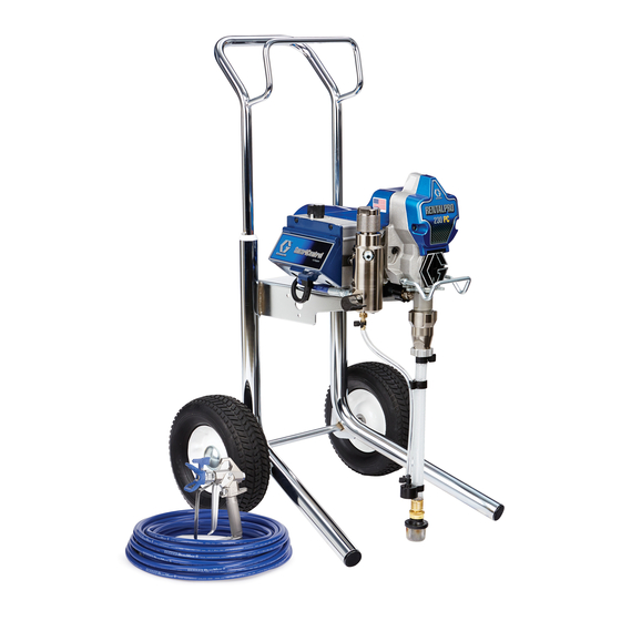
RentalPro 230 HDR
Electric Airless Sprayer
For Portable Airless Spraying of Architectural Coatings and Paints.
3300 psi (227 bar, 22.7 MPa) Maximum Working Pressure
Important Safety Instructions
Read all warnings and instructions in this
manual, and on the unit, including the
power cord. Save these instructions.
Model 24V658
Related Manuals:
312830
309250
333402A
ti23570a
110474
Certified to CAN/CSA C22.2 No. 68
Conforms to UL 1450
EN
Advertisement
Table of Contents

Related Manuals for Graco RentalPro 230 HDR


Summary of Contents for Graco RentalPro 230 HDR
- Page 1 Operation, Repair, Parts RentalPro 230 HDR 333402A Electric Airless Sprayer For Portable Airless Spraying of Architectural Coatings and Paints. 3300 psi (227 bar, 22.7 MPa) Maximum Working Pressure Important Safety Instructions Read all warnings and instructions in this manual, and on the unit, including the power cord.
-
Page 2: Table Of Contents
Spray Tip Installation .....14 Graco Standard Warranty ....32 Spraying . -
Page 3: Warnings
Warnings Warnings The following warnings are for the setup, use, grounding, maintenance, and repair of this equipment. The exclama- tion point symbol alerts you to a general warning and the hazard symbols refer to procedure-specific risks. When these symbols appear in the body of this manual or on warning labels, refer back to these Warnings. Product-specific hazard symbols and warnings not covered in this section may appear throughout the body of this manual where applicable. - Page 4 Check hoses and parts for signs of damage. Replace any damaged hoses or parts. • This system is capable of producing 3300 psi (227 bar, 22.7 MPa). Use Graco replacement parts or accessories that are rated a minimum of 3300 psi (227 bar, 22.7 MPa).
- Page 5 Do not kink or over-bend the hose. • Do not expose the hose to temperatures or to pressures in excess of those specified by Graco. • Do not use the hose as a strength member to pull or lift the equipment.
-
Page 6: Component Identification
Component Identification Component Identification ti23572a Model/Serial Tag (below sprayer frame) ON/OFF Switch Power Cord Drain Tube Fluid Hose Suction Tube Pressure Control Filter Guard Trigger Lock Pail Hook Pump Smart Control 2.0 Display Fluid Outlet Prime / Spray Valve 333402A... -
Page 7: Grounding
Grounding Grounding Extension Cord Requirements The equipment must be grounded to reduce the risk of static sparking and electric shock. Electric or static sparking can cause fumes to ignite or explode. Improper grounding can cause electric shock. Grounding provides an escape wire for the electric current. - Page 8 Grounding Grounding a metal pail: connect a ground wire to the To maintain grounding continuity when flushing or pail by clamping one end to pail and other end to a true relieving pressure: hold metal part of spray gun firmly earth ground.
-
Page 9: Operation
Operation Operation Pressure Relief Procedure Follow the Pressure Relief Procedure whenever you see this symbol. ti2614a 4. Hold gun firmly to side of pail. Disengage trigger This equipment stays pressurized until pressure is lock and trigger the gun to relieve pressure. manually relieved. -
Page 10: Setup
Clear hose or tip obstruction. See Clearing Tip Clog, page 15. Setup ti2703a 4. Remove spray tip and guard from gun. 1. Connect Graco airless hose to sprayer. Tighten securely. 333402A... - Page 11 5. Check inlet strainer for clogs and debris. 8. Plug sprayer into grounded outlet. 9. Turn spray/prime valve down to PRIME position. ti2812a 6. Fill throat packing nut with Graco TSL to prevent premature packing wear. Do this each time you spray. Approximate Fill Level 10.
-
Page 12: Startup
Operation Startup 5. Allow fluid to flow out of prime tube into waste pail for 30 to 60 seconds. Turn pressure control knob left (counterclockwise) to minimum pressure. 1. Perform Pressure Relief Procedure, page 9. Turn pressure control knob left (counterclockwise) to min- imum pressure. - Page 13 Operation 10. Trigger gun into waste pail until paint comes out of gun. Release trigger, pump will build up pressure and motor will stop. Move gun to paint pail and trigger for 20 seconds. High-pressure spray is able to inject toxins into the body and cause serious bodily injury.
-
Page 14: Spray Tip Installation
Operation Spray Tip Installation Spraying 1. Spray a test pattern. Point gun straight at surface to be sprayed about 12 in (30 cm) away from surface, and begin moving the gun before you trigger it. 1. Perform Pressure Relief Procedure, page 9. 2. -
Page 15: Clearing Tip Clog
Operation Clearing Tip Clog 4. Engage trigger lock. SKIN INJECTION HAZARD Never point gun at your hand or into a rag! 1. Release trigger, engage trigger lock. 5. Return spray tip to original position. 2. Rotate spray tip. 6. Disengage trigger lock and continue spraying. 3. -
Page 16: Cleanup
Operation Cleanup 5. Engage trigger lock. Remove tip and guard from gun and place into waste pail for further cleaning. 1. Perform Pressure Relief Procedure, page 9. NOTE: Use water for water-base material, mineral spirits for oil-base material, or other solvents recom- 6. - Page 17 Operation 9. Trigger gun and increase pressure until flushing 13. Raise suction tube above flushing fluid and run fluid appears. sprayer for 15 to 30 seconds to drain flushing fluid. Turn power switch OFF. PAINT ti2820a ti2707a FLUSH 10. Move gun to waste pail, hold gun against paint pail 14.
- Page 18 Operation 17. Clean tip, guard, and inlet screen with a brush. 19. If flushing with water, flush again with mineral spir- Reassemble spray tip and guard. its, or Pump Armor, to leave a protective coating to prevent freezing or corrosion. 18.
-
Page 19: Digital Display
Digital Display Digital Display NOTE: LIFE displays briefly, then the number of gallons sprayed above 1000 psi (70 bar, 7 MPa). Operation Main Menu Short press to moves to next display. Press and hold (5 seconds) to change units or reset data. 1. - Page 20 Digital Display 3. S/N displays for 1 sec, then the serial number. Short 5. Press and hold DTS button to clear error code to press DTS button. Total motor run hours displays. zero. Short press to move to software REV. ti7489b 4.
-
Page 21: Troubleshooting
Troubleshooting Troubleshooting What to Do (When check is not OK, refer to this What to Check Type of Problem (if check is OK, go to next) column) Basic fluid pressure problems Pressure control knob setting. Motor Slowly increase pressure to see if will not run if at minimum setting (fully motor starts. - Page 22 Troubleshooting What to Do (When check is not OK, refer to this What to Check Type of Problem (if check is OK, go to next) column) Basic Electrical Problems Electric supply. Meter must read: Reset building circuit breaker. 85-130 VAC. Replace building fuse.
- Page 23 Troubleshooting What to Do (When check is not OK, refer to this What to Check Type of Problem (if check is OK, go to next) column) Low Output For worn spray tip. Perform Pressure Relief Proce- dure, page 9. Then replace tip. See your separate gun manual for addi- tional instruction.
- Page 24 Troubleshooting What to Do (When check is not OK, refer to this What to Check Type of Problem (if check is OK, go to next) column) Motor runs and pump strokes Leaking around throat packing nut Replace packings. Also check piston which may indicate worn or damaged valve seat for hardened paint or nicks packings.
- Page 25 Troubleshooting What to Do (When check is not OK, refer to this What to Check Type of Problem (if check is OK, go to next) column) ON/OFF switch. Be sure sprayer is Building circuit breaker opens as Replace ON/OFF switch. soon as sprayer is plugged into outlet unplugged! Disconnect wires from and sprayer is NOT turned on.
- Page 26 Troubleshooting Motor Control Board Diagnostics NOTICE Do not allow sprayer to develop fluid pressure without transducer installed. Leave drain valve open if test transducer is used. For sprayers with digital display, see Digital Display NOTE: Messages and table below. • Keep a new transducer on hand to use for test.
-
Page 27: Wiring Diagram
Wiring Diagram Wiring Diagram MOTOR Digital Display Potentiometer Ref 37 On/Off Switch Ref 30 Black Ground Pressure Transducer Ref 38 Power Plug Ref 56 Black Green White Black ti23580a 333402A... -
Page 28: Parts Drawing - Sprayer
Parts Drawing - Sprayer Parts Drawing - Sprayer Ref. Torque 9-11 in-lb (1.0 - 1.2 N•m) 23-27 in-lb (2.6 - 3.0 N•m) 30-35 in-lb (3.3 - 3.9 N•m) 130-150 in-lb (14.6 - 16.9 N•m) See page 30. 140-160 in-lb (15.8 - 18.0 N•m) 25-30 ft-lb (33.8 - 40.6 N•m) 37-43 ft-lb (50.1 - 58.3 N•m) 65-75 ft-lb (88.1 - 101.6 N•m) -
Page 29: Parts List Sprayer
287902 KIT, repair, filter cap, includes 18 63Y 15H085 LABEL, danger INSERT, filter 65Y 195793 LABEL, warning 15B120 GROMMET, transducer 109032 SCREW, pan hd 287901 COVER, front, Graco, paint includes 15E813 NUT, jam 12, 65 15C146 HOOK. pail 287900 SHIELD, motor, painted includes 12 287489 HANDLE... -
Page 30: Parts Control Box And Board
Parts Control Box and Board Parts Control Box and Board Ref. Torque 10-14 in-lb (1.1 - 1.5 N•m) 20-25 in-lb (2.2 - 2.8 N•m) 30-35 in-lb (3.3 - 3.9 N•m) 2-3 in-lb (0.23 - 0.34 N•m) ti23579a Parts List Ref. Part Description Qty. -
Page 31: Technical Data
Technical Data Technical Data RentalPro 230 HDR Electric Airless Sprayer U.S. Metric Sprayer Maximum Delivery 0.54 gpm 2.0 lpm Maximum Tip Size 0.023 0.023 Fluid Outlet npsm 1/4 in. 1/4 in. Cycles 620 per gallon 165 per liter Generator Minimum... -
Page 32: Graco Standard Warranty
With the exception of any special, extended, or limited warranty published by Graco, Graco will, for a period of twelve months from the date of sale, repair or replace any part of the equipment determined by Graco to be defective.
Need help?
Do you have a question about the RentalPro 230 HDR and is the answer not in the manual?
Questions and answers