Table of Contents
Advertisement
Quick Links
916PCP/916GCP
USER'S MANUAL
M/B For LGA 775 Pentium 4 Processor
NO. G03916GCPR206
Rev:2.0
Release date: August 2005
Trademark:
* Specifications and Information contained in this documentation are furnished for information use only, and are
subject to change at any time without notice, and should not be construed as a commitment by manufacturer.
Advertisement
Table of Contents

Related Manuals for JETWAY 916PCP


Summary of Contents for JETWAY 916PCP
- Page 1 916PCP/916GCP USER'S MANUAL M/B For LGA 775 Pentium 4 Processor NO. G03916GCPR206 Rev:2.0 Release date: August 2005 Trademark: * Specifications and Information contained in this documentation are furnished for information use only, and are subject to change at any time without notice, and should not be construed as a commitment by manufacturer.
-
Page 2: Table Of Contents
TABLE OF CONTENT USER’S NOTICE ..........................ii MANUAL REVISION INFORMATION.................... ii COOLING SOLUTIONS........................ii CHAPTER 1 INTRODUCTION OF 916PCP/916GCP MOTHERBOARD FEATURE OF MOTHERBOARD ..................1 1-1.1 PECIAL FEATURES OF MOTHERBOARD............2 SPECIFICATION........................3 PERFORMANCE LIST......................4 LAYOUT DIAGRAM & JUMPER SETTING..............5 CHAPTER 2 HARDWARE INSTALLATION HARDWARE INSTALLATION STEPS ................ -
Page 3: User's Notice
TRANSMITTED OR TRANSLATED INTO ANY LANGUAGE IN ANY FORM OR BY ANY MEANS WITHOUT WRITTEN PERMISSION OF THE MANUFACTURER. THIS MANUAL CONTAINS ALL INFORMATION REQUIRED TO USE 916PCP/916GCP MOTHER-BOARD AND WE DO ASSURE THIS MANUAL MEETS USER’S REQUIREMENT BUT WILL CHANGE, CORRECT ANY TIME WITHOUT NOTICE. -
Page 4: Chapter 1 Introduction Of 916Pcp/916Gcp Motherboard
4.0GB. These motherboards use the newest Intel 915P/915G Chipset Supports 533MHz/800MHz Processor System Bus (FSB) in data transfer rate, the 916PCP/916GCP provided DDR2 clock frequency support DDR2 533/400. These motherboard also provided Dual Channel function to increase memory performance. -
Page 5: 1-1.1 Pecial Features Of Motherboard
1-1.1 Special Features of motherboard Bi-turbo Technology ---( Hardware-based Dynamic Over-clocking ) The Bi-turbo Technology offers you dual over-clocking modes. On top of the software based BIOS setting “Current CPU Clock” for over-clocking, the onboard hardware circuitry will monitor the change of CPU current to activate 2 level over-clocking at preset workload level automatically. -
Page 6: Specification
∗ PS/2 keyboard and PS/2 mouse connectors Multi I/O ∗ Floppy disk drive connector x1 ∗ Parallel port x1, Serial port (x2 for 916PCP, x1 for 916GCP) ∗ USB 2.0 connector x4, headers x4 (connecting cable option) ∗ High Definition Audio connector (Line-in, MIC, 4x Line-Out) -
Page 7: Performance List
1-3 Performance List The following performance data list is the testing result of some popular benchmark testing programs. These data are just referred by users, and there is no responsibility for different testing data values gotten by users (the different Hardware & Software configuration will result in different benchmark testing results.) Performance Test Report CPU:... -
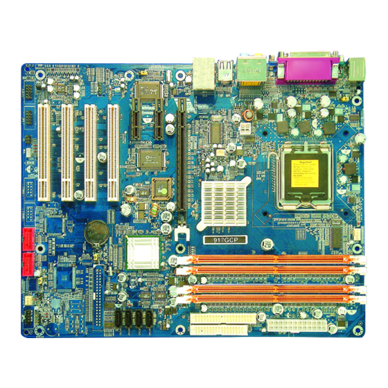
Page 8: Layout Diagram & Jumper Setting
CPUZ System / CPU Clock 200.0 / 3600.0 200.0 / 3600.0 1-4 Layout Diagram & Jumper Setting Line-OUT Line-IN Surrback PRINT PS/2 Mouse PS/2 Keyboard COM1 USB2 MIC-IN GEN/LFE SURROUND ATX 12V Power Connector CPU Socket PS2 KB/Mouse Port CPU FAN K/B Power ON Jumper (JP1) DDR DIMMx4... - Page 9 6 phone jack Connector P.23 VGA Display Connector 15-pin Female Connector P.23 (for 916GCP) COM2 Serial Port COM2 Connector 9-pin Connector P.23 (for 916PCP) COM1 Serial Port COM1 Connector 9-pin Connector P.23 Floppy Driver Connector 34-pin Block P.23 IDE1/IDE2 Primary/Secondary Connector 40-pin Block P.24...
-
Page 10: Chapter 2 Hardware Installation
Chapter 2 Hardware installation 2-1 Hardware installation Steps Before using your computer, you had better complete the following steps: 1. Check motherboard jumper setting 2. Install CPU and Fan 3. Install System Memory (DIMM) 4. Install Expansion cards 5. Connect IDE and Floppy cables, Front Panel /Back Panel cable 6. -
Page 11: Install Cpu
(2) Keyboard/USB Power On function Enabled/Disabled: JP1/JP3, JP5 When setting Enabled you can using keyboard by key in password/USB device to power on system. JP1 1-2 closed K/B Power ON Disabled (Default) JP1 2-3 closed K/B Power ON Enabled JP3 1-2 closed USB Power On Disabled (Default) JP3 2-3 closed USB Power On Enabled JP5 1-2 closed USB Power On Disabled (Default) JP5 2-3 closed USB Power On Enabled... -
Page 12: About Intel Pentium 4 Lga775 Cpu
2-3-2 About Intel Pentium 4 LGA775 CPU This motherboard provides a 775-pin surface mount, LGA775 Land Grid Array socket, referred to as the LGA775 socket supports Intel Pentium 4 processor in the 775 Pin package utilizes Flip-Chip Land Grid Array (FC-LGA4) package technology. The CPU that comes with the motherboard should have a cooling FAN attached to prevent overheating. -
Page 13: Lga 775 Cpu Installation Guide
2-3-3 LGA 775 CPU Installation Guide Socket Preparation Opening the socket: Note: Apply pressure to the corner with right hand thumb while opening/closing the load lever, otherwise lever can bounce back like a “mouse trap” and WILL cause bent contacts (when loaded) Socket Load Plate Open... - Page 14 Visually inspect for bent contacts (Recommend at least 1stpass visual inspection) NOTE: Refer to the Handling and Inspection Module for 1stand 2ndpass inspection details. NOTE: Glove images are for illustrative purposes only. Please consult local safety guidelines for specific requirements NOTE: Recommend not to hold the load plate as a lever, instead hold at tab with left hand, removing the PnP cap with right hand...
- Page 15 775-Land Package Removal Open the Load Plate/Lever with both hands: With left hand index finger and thumb to support the load plate edge, engage PnP cap with right hand thumb and peel the cap from LGA775 Socket while pressing on center of PnP cap to assist in removal. Pick up 775-land LGA package: By Vacuum Pen: Place a minimum 9-mm cup at approximately the center of IHS.
- Page 16 Visually inspect socket contact array 1. First Pass Inspection Scan socket contact array at varying angles noting the presence of any foreign material If foreign material can’t be blown off by compressed air, or mechanical damage (Mode1 or 4) observed, reject the motherboard for further evaluation or socket replacement. 2.
- Page 17 NOTE: Thermal Solutions that come with IntelR boxed processor use pre-applied thermal interface material Apply Thermal Interface Material and not grease. Remove Heat Sink (HS) from packaging media Place HS onto the LGA775 Socket • Ensure fan cables are oriented on side closest to fan header •...
- Page 18 Intel Reference Thermal Solution Disassembly Rotate fastener cap. turn to un-lock Pull up fastener cap to un-seat 12 Disconnect fan cable from motherboard header Turn fastener caps (4) counter-clock wise 90degrees to the un-locked position • A flat-bladed screwdriver may be used if required Pull up on fastener caps to unseat Manually remove HS with gentle twist motion.
- Page 19 Remove the heatsink from the socket Gently push loose thermal interface material (TIM) to center of processor (pictures 2 and 3) Remove pieces with dry cloth (picture 4) Wipe with dry, lint-free cloth to remove most of the material (picture 5) Wet another lint-free cloth with isopropyl alcohol (IPA) and wipe to clean remaining material (picture 6) Be careful to remove material from gaps between processor and load plate...
- Page 20 Replacing Damaged Fasteners • To prevent damage, avoid setting the thermal solution with the prongs down − Set on heatsink side or with fan down • The plastic fasteners on the heatsink can be replaced. − Use Shop Intel to order spare fasteners −...
- Page 21 Tilt to remove Replacing Fasteners • To replace the fastener − Start with the white prong − Note the “keying” notch feature − Tilt the prong to insert into the heatsink leg. − Holding the white prong without bending it, push the black pin on from the bottom until you hear a single “click”...
-
Page 22: Install Memory
2-4 Install Memory This motherboard provides four 240-pin DDR2 DUAL INLINE MEMORY MODULES (DIMM) sites for memory expansion available from minimum memory size of 256MB to maximum memory size of 4.0GB DDR2 SDRAM. Valid Memory Configurations Bank 240-Pin DIMM Total Memory Bank 0, 1 (DIMM1) DDR2 400/ DDR2 533 256MB∼1.0GB... -
Page 23: Expansion Card
2-5 Expansion Cards WARNING! Turn off your power when adding or removing expansion cards or other system components. Failure to do so may cause severe damage to both your motherboard and expansion cards. 2-5-1 Procedure For Expansion Card Installation 1. Read the documentation for your expansion card and make any necessary hardware or software setting for your expansion card such as jumpers. -
Page 24: Interrupt Request Table For This Motherboard
2-5-3 Interrupt Request Table For This Motherboard Interrupt request are shared as shown the table below: INT A INT B INT C INT D INT E INT F INT G INT H √ Slot 1 √ Slot 2 √ Slot 3 √... -
Page 25: Connectors, Headers
2-6 Connectors, Headers 2-6-1 Connectors (1) Power Connector (24-pin block) : ATXPWR ATX Power Supply connector. This is a new defined 24-pins connector that usually comes with ATX case. The ATX Power Supply allows to use soft power on momentary switch that connect from the front panel switch to 2-pins Power On jumper pole on the motherboard. - Page 26 GEN/LEF: (GRAY) Audio output to speaker-Side speaker out (10) Serial Port COM1/COM2(COM2 only for 916PCP) : COM1/COM2 is the 9-pin D-Subminiature mail connector. The On-board serial port can be disabled through BIOS SETUP. Please refer to Chapter 3 “INTEGRATED PERIPHERALS SETUP”...
- Page 27 Pin 1 Floppy Drive Connector (12) Primary IDE Connector (40-pin block): IDE1 (Support ATA 100) This connector supports the provided IDE hard disk ribbon cable. After connecting the single plug end to motherboard, connect the two plugs at other end to your hard disk(s). If you install two hard disks, you must configure the second drive to Slave mode by setting its jumpers accordingly.
-
Page 28: Headers
2-6-2 Headers Line-Out, MIC Header (9-pin): AUDIO This header connect to Front Panel Line-out, MIC connector with cable. AUDIO Pin 1 Line-Out, MIC Headers USB Port Headers (9-pin) : USB3, USB4 The header is used for connecting the additional USB port plug. By attaching an option USB cable, your can be provided with two additional USB plugs affixed to the back panel. - Page 29 PWRLED Pin 1 JW FP SPEAK Pin 1 Pin 1 System Case Connections FAN Power Headers: SYSFAN1, SYSFAN2 (3-pin), CPUFAN (4-pin) These connectors support cooling fans of 350mA (4.2 Watts) or less, depending on the fan manufacturer, the wire and plug may be different. The red wire should be positive, while the black should be ground.
- Page 30 (10) CD Audio-In Headers (4-pin) : CDIN CDIN are the connectors for CD-Audio Input signal. Please connect it to CD-ROM CD-Audio output connector. C DIN CD Audio-In Headers (11) SPDIF In/Out Header: JP6 JP 6 Pin 1 SPDIF-Bracket Connector...
-
Page 31: Starting Up Your Computer
2-7 Starting Up Your Computer 1. After all connection are made, close your computer case cover. 2. Be sure all the switch are off, and check that the power supply input voltage is set to proper position, usually in-put voltage is 220V∼240V or 110V∼120V depending on your country’s voltage used. -
Page 32: Chapter 3 Introducing Bios
Chapter 3 Introducing BIOS The BIOS is a program located on a Flash Memory on the motherboard. This program is a bridge between motherboard and operating system. When you start the computer, the BIOS program gain control. The BIOS first operates an auto-diagnostic test called POST (power on self test) for all the necessary hardware, it detects the entire hardware device and configures the parameters of the hardware synchronization. -
Page 33: The Main Menu
3-3 The Main Menu Once you enter Award ® BIOS CMOS Setup Utility, the Main Menu (Figure 3-1) will appear on the screen. The Main Menu allows you to select from fourteen setup functions and two exit choices. Use arrow keys to select among the items and press <Enter> to accept or enter the sub-menu. -
Page 34: Standard Cmos Features
Power User Overclock Settings Use this menu to specify your settings (frequency, Voltage) for overclocking demand Password Settings This entry for setting Supervisor password and User password Load Optimized Defaults Use this menu to load the BIOS default values these are setting for optimal performances system operations for performance use. -
Page 35: Advanced Bios Features
Time The time format is <hour><minute><second>. Primary Master/Primary Slave Secondary Master/Secondary Slave Press PgUp/<+> or PgDn/<–> to select Manual, None, Auto type. Note that the specifications of your drive must match with the drive table. The hard disk will not work properly if you enter improper information for this category. - Page 36 Anti-Virus Protection Allows you to choose the VIRUS Warning feature for IDE Hard Disk boot sector protection. If this function is enabled and someone attempt to write data into this area, BIOS will show a warning message on screen and alarm beep. Disabled (default) No warning message to appear when anything attempts to access the boot sector or hard disk partition table.
-
Page 37: Advanced Chipset Features
Typematic Rate Setting Keystrokes repeat at a rate determined by the keyboard controller. When enabled, the typematic rate and typematic delay can be selected. The settings are: Enabled/Disabled. Typematic Rate (Chars/Sec) Sets the number of times a second to repeat a keystroke when you hold the key down. The settings are: 6, 8, 10, 12, 15, 20, 24, and 30. -
Page 38: Pciexpress Root Port Function
PCIExpress Root Port Function Please refer to section 3-6-1 System BIOS Cacheable Selecting Enabled allows caching of the system BIOS ROM at F0000h-FFFFFh, resulting in better system performance. However, if any program writes to this memory area, a system error may result. The settings are: Enabled and Disabled. Video RAM Cacheable Select Enabled allows caching of the video BIOS, resulting in better system performance. -
Page 39: Integrated Peripherals
3-7 Integrated Peripherals CMOS Setup Utility – Copyright(C) 1984-2004 Award Software Integrated Peripherals > Onboard IDE Function Press Enter Item Help > Onboard Device Function Press Enter > Onboard Super IO Function Press Enter Init Display First PCI Slot Menu Level > Pwr Status After Pwr Failure Always Off ↑... -
Page 40: Onboard Device Function
OnChip IDE Primary/Secondary The integrated peripheral controller contains an IDE interface with support for two IDE channels. Select Enabled to activate each channel separately. The settings are: Enabled and Disabled. Primary/Secondary Master/Slave PIO The four IDE PIO (Programmed Input/Output) fields let you set a PIO mode (0-4) for each of the four IDE devices that the onboard IDE interface supports. -
Page 41: Onboard Super Io Function
3-7-3 Onboard Super IO Function Phoenix – AwardBIOS CMOS Setup Utility Onboard Super IO Function Onboard FDD Controller Enabled Item Help Onboard Serial Port 1 3F8/IRQ4 Onboard Serial Port 2 2F8/IRQ3 UART2 Mode Select Normal Menu Level >> IR Duplex Mode Half IR Pins IRRX/IRTX... -
Page 42: Power Management Setup
3-8 Power Management Setup The Power Management Setup allows you to configure your system to most effectively save energy saving while operating in a manner consistent with your own style of computer use. Phoenix – AwardBIOS CMOS Setup Utility Power Management Setup ACPI Function Enabled Item Help... -
Page 43: Pm Timer Reload Events
Wake-Up by PCI card /Power On by Ring During Disabled, the system will ignore any incoming call from the PCI card/modem. During Enabled, the system will boot up if there’s an incoming call from the PCI card /modem. Wake-Up on RTC Alarm This function is for setting date and time for your computer to boot up. -
Page 44: Pnp/Pci Configuration Setup
3-9 Miscellaneous Control This section is for setting CPU Frequency/Voltage Control. Phoenix – AwardBIOS CMOS Setup Utility Miscellaneous Control Auto Detect PCI Clock Enabled Item Help Spread Spectrum Disabled Flash Port Write Protect Enabled Menu Level > > IRQ Resources Press Enter PCI/VGA Palette Snoop Disabled... -
Page 45: Pc Health Status
This section shows the Status of you CPU, Fan, Warning for overall system status. This is only available if there is Hardware Monitor onboard. Phoenix – AwardBIOS CMOS Setup Utility PC Health Status Shutdown Temperature Disabled Item Help Show PCHealth in Post Enabled >... -
Page 46: Bi-Turbo Configuration
This item allows you setting the FAN works in full speed when the temperature over the value which out set. If the temperature below the value but over the Idle Temperature, the FAN will works over 60% of full speed, and the higher temperature will gain higher FAN speed, after over the temperature which this item setting, the FAN works in full speed. -
Page 47: Power User Overclock Settings
Phoenix – AwardBIOS CMOS Setup Utility Power User Overclock Settings Item Help CPU Clock Ratio *** Current Host/PCI Clock is 133/33 MHz *** Host/PCI Clock at Next Boot Menu Level > *** Current DRAM Clock is 166MHz *** DRAM Clock at Next Boot By SPD(DDR CPU Vcore Select Default... -
Page 48: Load Standard/Optimized Defaults
User password: Can only enter but do not have the right to change the options of the setup menus. When you select this function, the following message will appear at the center of the screen to assist you in creating a password. ENTER PASSWORD: Type the password, up to eight characters in length, and press <Enter>. -
Page 49: Chapter 4 Driver & Free Program Installation
DRIVER & FREE PROGRAM INSTALLATION Check your package and there is A MAGIC INSTALL CD included. This CD consists of all DRIVERS you need and some free application programs and utility programs. In addition, this CD also include an auto detect software which can tell you which hardware is installed, and which DRIVERS needed so that your system can function properly. -
Page 50: Vga Install Intel 915G Vga Driver
1. Click INF in the MAGIC INSTALL MENU 2. Click NEXT when Chipset Software Install Utility appears 3. This license agreement appear, click Yes, the 4. Select if you want computer re-started click readme information appear, click Next Finish 4-2 VGA install Intel 915G VGA Driver (For 916GCP) 1. - Page 51 3. Click YES, This is Announce CopyRight 4. If You Want Re-start Computer , Click FINISH 4-3 SOUND install ALC880 AC97 Codec Audio Driver 1. Click SOUND when MAGIC INSTALL 2. Click NEXT When Realtek High Definition MENU appears Audio driver windows appear 3.
-
Page 52: Lan Install Realtek 10/100 Ethernet Driver
5. Speaker configuration setting 6. SPDIF out setting 4-4 LAN Install Realtek 10/100 Ethernet Driver WINDOWS 2000/XP Setup 1. Click LAN when Magic Install Menu appear 2. Click NEXT, install REALTEK Gigabit and Fast Ethernet NIC Driver 3. After driver installation completed, Click Finish... -
Page 53: Pc-Health Install Winbond Hardware Doctor Utility
4-5 PC-HEALTH install Winbond Hardware Doctor Utility 1. Click PC-HEALTH when MAGIC INSTALL 2. Click Next when Install shield wizard Window MENU appears appears, Choose destination location and click Next, select program folder and click next 3. Click FINISH and restart your computer 4. - Page 54 PC-CILLIN Install PC-CILLIN 2004 Anti-virus program Click PC-CILLIN when MAGIC INSTALL Click NEXT when the "Trend Micro internet MENU appear security" installshield wizard windows appear This is license agreement, select "I Accept Click NEXT and Enter your Customer the terms" and Click NEXT Information, Click NEXT or choose Change to change the path for the file to be stored Click INSTALL, Start to install the software...
-
Page 55: How To Update Bios
STEP 2. Copy utility program to your boot disc. You may copy from DRIVER CD X:\FLASH\AWDFLASH.EXE or download from our web site. STEP 3. Copy latest BIOS for 916GCP/916PCP from our web site to your boot disc. STEP 4. Insert your boot disc into A:, start the computer, type “Awdflash A:\916GCPAxxx.BIN /SN/PY/CC/R”...
Need help?
Do you have a question about the 916PCP and is the answer not in the manual?
Questions and answers