Table of Contents
Advertisement
PCI/ AGP Mainboard
For Pentium
The author assumes no responsibility for any errors or omissions which
may appear in this document nor does it make a commitment to update
the information contained herein.
Trademark:
*
Pentium is registered trademark and MMX is a trademark of Intel corporation,
the other names and brands are the property of their respective owners.
*
Specifications and Information contained in this documentation are furnished for information use only, and are subject to
change at any time without notice, and should not be construed as a commitment by manufacturer.
994AN/994AN-L
994AS/994AS-L
USER'S MANUAL
II/ III or Socket 370
NO. G03-994ANR4A
Release date: NOV 2000
** Year 2000 compliant **
Advertisement
Table of Contents

Related Manuals for JETWAY 994ANR4A


Summary of Contents for JETWAY 994ANR4A
- Page 1 The author assumes no responsibility for any errors or omissions which may appear in this document nor does it make a commitment to update the information contained herein. NO. G03-994ANR4A Release date: NOV 2000 ** Year 2000 compliant ** Trademark: Pentium is registered trademark and MMX is a trademark of Intel corporation, the other names and brands are the property of their respective owners.
-
Page 2: Table Of Contents
TABLE OF CONTENT Chapter 1 1-1 Preface......................1 1-2 Feature of motherboard..................1 1-2-1 Overview....................1 1-2-2 Key Feature ..................2 Chapter 2 Hardware Installation .................. 3 2-1 Unpacking ......................3 2-2 Mainboard Diagram ..................4 2-3 Quick Reference for Jumpers, Connectors & Expansion Socket ....... 5 2-4 Installation Steps.................... -
Page 3: Preface
Chapter 1 1-1 Preface Thank you for purchasing this multifunction motherboard. It has the most flexibility you can find Pentium ® II / Pentium ® III in today’s computer market. The mainboard integrates both Intel & Celeron™(Slot 1) / Coppermine processor and Celeron™ (Socket 370) PPGA / FCPGA processor interface into a compact PC/ATX compatible system along with next generation of 4X AGP specification, 133MHz FSB, Ultra DMA66, and optional 3D Stereo Sound System audio chip. - Page 4 • Multi-Speed Support ¡ G Provide 66/75*/83*/95*/100/112*/117*/124*/133*/140*MHz Front Pentium ® II / Pentium ® III Side Bus Frequency to support Intel / Coppermine / Celeron processor for Slot1 interface or Intel Celeron PPGA / FCPGA on a ZIP Socket 370 interface. •...
-
Page 5: Hardware Installation
Hardware Installation 2-1 Unpacking This mainboard package should contain the following: • The mainboard • USER’S MANUAL for mainboard • Cable set for Ultra DMA 66 IDE x1, Floppy x1 • CD for Drivers PACK The mainboard contains sensitive electronic components that can be easily damaged by electron-static, so the mainboard should be left in its original packing until it is installed. -
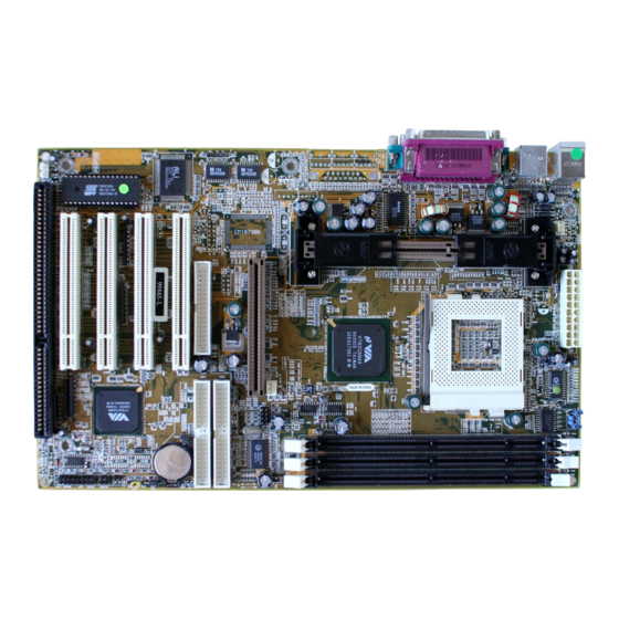
Page 6: Quick Reference For Jumpers, Connectors & Expansion Socket
ATX POWER CONN. CPUFAN DIMM1 DIMM2 DIMM3 GAME1 VIA82C694X SYSFAN SPKIN 1 AGP1 IDE2 IDE2 SPDIFIN 1 IDE1 IDE1 SPDIFO UT JP 1 PCI1 PCI 1 BATT. PCI2 ALI M5135 PCI 2 PCI3 VIA82C596B PCI 3 PCI4 PCI 4 Figure 2-2 Option for motherboard that embedded with Audio Chip 2-3 Quick Reference for Jumpers, Connectors &... -
Page 7: Expansion Sockets
Jumper Name Description Page CPU Bus Frequency Selection Refer to page 6 p. 6 CPU Ratio Selector Refer to page 6 p. 6 JP16 CMOS RAM Clear 1-2 Normal ,2-3 Clear CMOS p. 7 Connectors Connector Name Description Page ATX Power Connector 20-Pin Block MINI-DIN PS/2 Keyboard/PS/2 Mouse... -
Page 8: Jumper Settings
2. Install the CPU 3. Install DRAM Modules 4. Install Expansion card Connect Cables, Wires, and Power Supply 2-5 Jumper Settings 1. CPU Bus Frequency Selection : CPU External Frequency¡ G U19 5 6 7 8 66.8 1 2 3 4 5 6 7 8 *Your Memory must meet the requirement to run on 133MHz or 140MHz 1 2 3 4... -
Page 9: System Memory (Dram)
Connect a jumper Cap over this jumper for a few seconds, will clears information stored in the CMOS RAM Chip that input by user, such as hard disk information and passwords. After CLEAR CMOS, you must enter the BIOS setup (by holding down <DEL> during power-up) to re- enter BIOS information (see BIOS SETUP). - Page 10 right angle. Insert the CPU with the white dot as your guide. The white dot should point towards the end of the level. The CPU has a corner pin for three of the four corners, the CPU will only fit in the one orientation as shown as follow.
-
Page 11: Cpu Insertion
FC-PGA with a PPGA heatsink CPU Insertion Step 1 Open the socket by raising the actuation lever. Step 2 Insert the processor. Ensure proper pin 1 orientation by aligning the FC-PGA corner marking with the socket corner closest to the actuation arm tip. -
Page 12: Expansion Cards
2-8 Expansion Cards You must read the documentation come with expansion card for any hardware or software settings that may be required to setup your specific card. Installation Procedure: 1. Read the documentation from your expansion card. 2. Set any necessary jumpers on your expansion card. 3. -
Page 13: External Connectors
Some devices may also need to use a DMA (Direct Memory Access) channel. DMA assignments for this mainboard are handled the same way as the IRQ assignment process described above. You can select a DMA channel in the PCI and PnP configuration section of the BIOS Setup utility. - Page 14 Parallel Port Connector 5. Serial Port COMA, COMB: COM1, COM2 COMA is the 9-pin D-Subminiature mail connector. The On-board serial port can be disabled through BIOS SETUP. Please refer to Chapter 3 “INTEGRATED PERIPHERALS SETUP” section for more detail information. COM1 COM2 Serial port COMA,COMB Connector...
- Page 15 to be both Masters using one ribbon cable on the primary IDE connector and another ribbon cable on the secondary IDE connector. Pin 1 Secondary IDE Connector 9. IDE activity LED: HDLED This connector connects to the hard disk activity indicator light on the case. HDLED IDE (Hard Drive) LED 10.
- Page 16 Turbo LED Turbo SW Reset SW Power LED Speaker Lock Keyboard System Case Connections 15. IR infrared module connector: IR1 This connector supports the optional wireless transmitting and receiving infrared module. This module mounts to small opening on system cases that support this feature you must also configure the setting through BIOS setup.
- Page 17 ¡ ° Wake On LAN Function worked only when power supply support 5VSB more than 750mA current. Jumpers & Connectors (Option for motherboard that emedded Audio chip) 19. On Board Audio chip Enabled / Disabled connector: JP4 1-2 closed: Disabled 2-3 closed: Enabled 20.
-
Page 18: Chapter 3 Award Bios Setup
23. PC Speaker signal Input connector: SPKIN 1 SPKIN 1 24. SPDIF (Sony / Philips Digital Interface) Input / Output Connectors: SPDIFIN 1 / SPDIFOUT SPDIFOUT SPDIFIN SPDIFOUT SPDIFIN 1 25. Optical kit connector: JP9 This connector is for user that has Optical kit(optional) to provide other set of SPDIF INPUT and SPDIF OUTPUT function. - Page 19 Award’s ROM BIOS provides a built-in Setup program which allows user modify the basic system configuration and hardware parameters. The modified data will be stored in a battery-backed CMOS RAM so data will be retained even when the power is turned off. In general, the information saved in the CMOS RAM stay unchanged unless here is configuration change in the system, such as hard drive replacement or new equipment is installed.
-
Page 20: Standard Cmos Features
Load Optimal Defaults: Use this menu to load the Optimal default values for the higher performance for your system to operate. See section 3-9 for the details. Load Standard Defaults: Use this menu to load the BIOS default values that are factory settings for normal/stable performance system operations. -
Page 21: Advanced Bios Features
IDE HDD Auto-Detection Press Enter Item Help IDE Primary Master Auto Menu Level Access Mode Auto To auto-detect the HDD’s size, Capacity head... on this channel Cylinder Head Precomp Landing Zone Sector ↑↓←→Move Enter: Select +/-/PU/PD: Value F10:Save ESC: Exit F1:General Help F5:Previous Values F6:Fail-Safe Defaults... - Page 22 Enabled Activates automatically when the system boots up causing a warning message to appear when anything attempts to access the boot sector or hard disk partition table. Disabled No warning message will appear when anything attempts to access the boot sector or hard disk partition table. CPU Internal Cache/External Cache: These two categories speed up memory access.
-
Page 23: Advanced Chipset Features
Setup The system will boot, but access to Setup will be denied if the correct password is not entered at the prompt. Note: To disable security, select PASSWORD SETTING at Main Menu and then you will be asked to enter password. Do not type anything and just press <Enter>, it will disable security. Once the security is disabled, the system will boot and you can enter Setup freely. -
Page 24: Integrated Peripherals
Delay Transaction: The chipset has an embedded 32-bit posted write buffer to support delay transactions cycles. Select Enabled to support compliance with PCI specification version 2.1. The Choice: Enabled, Disabled. INTEGRATED PERIPHERALS The “INTEGRATED PERIPHERALS” section mainly deals with I/O function. These functions will be necessary only when the system I/O malfunctioned or the system is unable to detects your CD-ROM or hard disk. -
Page 25: Power Management Setup
Onboard Serial Port 1/Port 2: Select an address and corresponding interrupt for the first and second serial ports. The choice: 3F8/IRQ4, 2E8/IRQ3, 3E8/IRQ4, 2F8/IRQ3, Disabled, Auto. 3-5 POWER MANAGEMENT SETUP The Power Management Setup allows you to configure you system to most effectively save energy while operating in a manner consistent with your own style of computer use. -
Page 26: Pnp/Pci Configurations
Suspend Type: Select the Suspend Type. The choice: PWRON Suspend, Stop Grant. MODEM Use IRQ: This determines the IRQ in which the MODEM can use. The choice: 3, 4, 5, 7, 9, 10, 11, NA. Suspend Mode: When enabled and after the set time of system inactivity, all devices except the CPU will be shut off. -
Page 27: Pc Health Status
assigning the interrupt resource automatically you can select “manual”, it will allow you to choose specific resources by going into each of the sub menu that follows this field (a sub menu is preceded by a “ ”). The choice: Auto(ESCD), Manual . IRQ Resources: When resources are controlled manually, assign each system interrupt a type, depending on the type of device using the interrupt. -
Page 28: Load Optimal Defaults
Auto Detect DIMM/PCI Clk Enabled Item Help Spreed Spectrum Disabled CPU Host/PCI Clock Default Menu Level ↑↓←→ Move Enter: Select +/-/PU/PD: Value F10:Save ESC: Exit F1:General Help F5:Previous Values F6:Fail-Safe Defaults F7:Optimized Defaults Figure 3-8 DIMM/PCI CLK: This item allows you to enable/disable auto detect DIMM/PCI Clock. The choice: Enabled, Disabled. -
Page 29: Set Supervisor/User Password
supervisor password : can enter and change the options of the setup menus. user password : just can only enter but do not have the right to change the options of the setup menus. When you select this function, the following message will appear at the center of the screen to assist you in creating a password. -
Page 30: Pc Health Monitor-Iii
We recommend to install all the Driver which this utility show in Screen ,because it will increase the system performance and solve the compatibility problem between system chipset and other device. For Example , You have to install this driver before you install AGP VGA driver otherwise it can’t install your VGA Driver succeed. - Page 31 General Description The PC HEALTH MONITOR-III Software, an application software based on Microsoft Windows 95, is used to control the PC HEALTH MONITOR CHIP. It can monitor the temperatures, power supply voltages and fan speeds via PC HEALTH MONITOR CHIP and show the information on screen periodically.
- Page 32 There values is used to specify the Temp-Over register/ Tem-under register of PC HEALTH MONITOR CHIP, If the temperature of the external thermistor is higher than this value and “System/CPU” is enabled in Monitoring Config. the monitor software will pop up a window to inform user.
- Page 33 Full duplex playback and recording, 120dB audio quality measured. Auto detectable SPDIF/IN signal level from 0.5V to 5V. • Stereo Mixer and FM Music Synthesizer Stereo analog mixing from CD-Audio, Line-in Stereo digital mixing from Voice, FM/Wave-table, Digital CD-Audio Mono mixing from MIC and software adjustable volume OPL3 FM synthesizer (4 operators) Up to 15 melody sounds and 5 rhythm sounds (20 voices) •...
- Page 34 in Win95 “X:\CMI8738\Win9X\APP\Win95\SETUP.EXE” in Win98 “X:\CMI8738\Win9X\APP\Win98\SETUP.EXE” 11. Click “OK” to start the installation procedure, and follow the on-screen instructions to finish the installation. When all the application softwares have been installed, please shut down Windows 95/98 system, and reboot your system. Win95/98 Un-Installation If you install Win95/98 and a sound card at the same time, you might experience some technical difficulties(the device might not function properly).
- Page 35 This Audio Rack consists of several major components: Control Center: Controls the display of the PCI Audio Rack’s components. MIDI Player: Plays MIDI music files, and allows you to create your personal song playlists, and play the song files. Wave Player: Records and plays digital audio (wave) files. Allows you to create wave file playlists, and playback the wave files.
- Page 36 Mixer panel while the four speakers mode is enabled. Mixer panel while the four speakers mode is disabled. Volume Control: Clicking on this button shows and allows you to use the output level controls. Recording Control: Clicking on this button shows and allows you use the input level controls. Input and Output Level Sliders and Buttons : For each input or output signal type, the control slider controls the loudness whereas the horizontal slider controls the balance between the two speakers.
- Page 37 enabled, and when it is not lit, it means it is mute. Several output signals can usually be enabled at once. MP3 Player : MP3 player can play both wave files and MP3 files. MP3 player while the loop function enables. The settings’...
- Page 38 Execute the "Helicopter" demo within the C3D HRTF Positional Audio Demos of this audio adapter. When the helicopter flies behind you, the rear speakers will work. Optical Kid for SPDIF/OUT (Option for motherboard that embedded PC Health chip) The Optical Kid includes¡ G Optical Module Optical Cable Software DVD driver...
- Page 39 When all the procedures have been completed, there will be an infrared signal coming from the SPDIF/OUT of the optical fiber of the sound card.
- Page 40 Please note that signal beam may cause severe damage to the eyes. For your safety, please point the output end to a piece of white paper to check if thebeam is in function . Please connect the output signal to the MD input, then play the music via the MP3 player.
- Page 41 Please note that in playback, if there is no gap longer than three seconds between each track, the MD can not recognize the tracks and will record all of them into one. It is recommended that you set the gap time to 3~5 seconds to meet all type of MD requirements. About Recording 24bit Audio Setting...
- Page 42 24-bit audio can only be applied to SPDIF IN/OUT mode; it does not apply to other modes such as the four channels or the analog. No sound will be heard while in playback, yet it can be recorded. The un-selected area will be gray out.
- Page 43 The un-selected area will be gray out. The un-selected area will be gray out. You can double-click this circuit icon to have the following setting box. By means of this setting box, you can also complete the above-mentioned setting procedures.
- Page 44 SPDIF/IN for motherboard that embedded Audio chip An example of Portable CD Player(Output) to Main Board (Optical Input)Setup...
- Page 45 When the connection is done, please go to the Start menu and select PCI Audio Applications\Audio Environment Setting Loopback(bypass)mode setup CD ROM(Digital Output) to SPDIF/IN Setup...
- Page 46 When the connection is done, please go to the Start menu and select PCI Audio Applications\Audio Environment Setting...
- Page 47 Please follow these setting procedures. Now you can insert the CD into the CD ROM drive, then activate C-MEDIA CD player and push the ”play” button to do the recording job. Please note that you have to set the MD in the simultaneous-recording mode. Magic lnstall...
- Page 48 This installation program automatic detects the motherboard you are using and shows you all the available drivers for this motherboard at right side of screen (please refer to diagram below). For installation procedure, please follow instructions on screen to install all the correspond drivers. An example of Magic Install (This installation program only supports Windows 95/98) Version 1.0 : Shows you the version of Magic Install.
Need help?
Do you have a question about the 994ANR4A and is the answer not in the manual?
Questions and answers