Table of Contents
Advertisement
Advertisement
Chapters
Table of Contents

Related Manuals for Daikin RZVF50


Summary of Contents for Daikin RZVF50
- Page 33 DR18-1226C Daikin IM & OM A-4 Size 3P542797-1-KA B, 40P, Dt:26-07-19...
-
Page 34: Table Of Contents
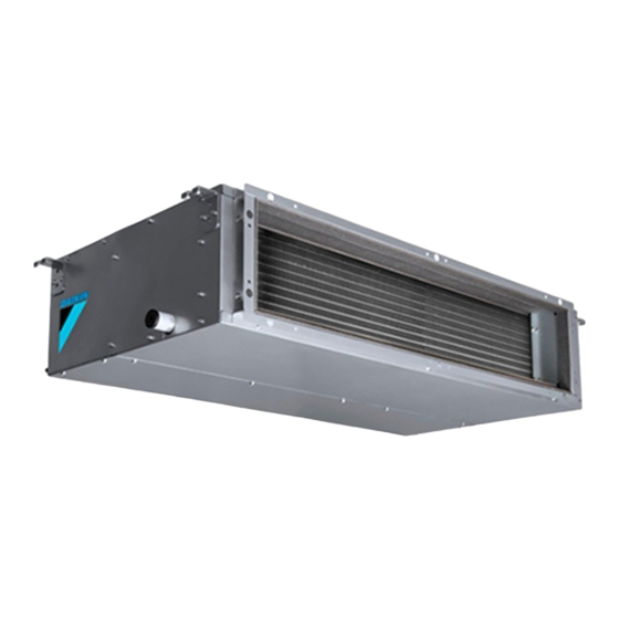
FDMF50BRV16 FDMF100BRV16 SPLIT SYSTEM Installation manual FDMF71BRV16 FDMF125BRV16 Air Conditioner FDMF140BRV16 FDMF90BRV16 CONTENTS • After the installation is completed, test the air conditioner and check if the air conditioner operates properly. Give the 1. SAFE TY PRECAUTIONS ..........34 user adequate instructions concerning the use and cleaning of the indoor unit according to the Operation Manual. -
Page 35: Before Installation
• Earth the air conditioner. 3. Where there is machinery which emits electromagnetic Do not connect the earth wiring to gas or water piping, waves. lightning conductor or telephone earth wiring. Electromagnetic waves may disturb the control system, Incomplete earthing may cause electric shocks or a fire. and cause malfunction of the equipment. - Page 36 2-2 OPTIONAL ACCESSORIES (1) Determine the route to carry the unit into the room. (2) Do not unpack the unit until it is carried to the • A remote controller is required for the indoor unit. (No remote controllers are required for multi slave units installation location.
-
Page 37: Selection Of Installation Location
2. Items to be checked at delivery 3. SELECTION OF INSTALLATION LOCATION Hold the hangers at 4 locations to move the indoor unit Items to be checked Check column when unpacking or after unpacked, and do not apply force Have you carried out field setting? (if necessary) to the piping (refrigerant and drain) and air outlet flange. -
Page 38: Preparation Before Installation
140 type • Inspection hatch <Failure example> If there is an obstacle in the airflow path or proper installation (45 0 x45 0 ) space is not provided, the indoor unit will cause air volume r·-·-· - Hanging bolt (x 4) (Hanging bolt pitch) reduction and take in air blown out of the indoor unit, i'v/! -
Page 39: Installation Of Indoor Unit
(4) Open installation holes 5. INSTALLATION OF INDOOR UNIT (in the case of installation onto the existing ceiling). Depending on the optional parts, it may be easier to attach • Open the installation holes on the ceiling of the them before installing the indoor unit. Refer to also the installation location, and work on the refrigerant piping, installation manual attached to the optional parts. -
Page 41: Refrigeran T Piping Work
• Before brazing refrigerant piping, have nitrogen flow On completion of installation work, check that there is no gas through the refrigerant piping and substitute air with nitro leakage. Refer to the illustrations on the right hand side and be sure (Refer to Fig. - Page 42 <In case of sticking vinyl tape> Support bracket 1 -1.5 m Vinyl tape Stick vinyl tape without "- tearing the sealing material( )· � � Downward slope of at least 1/100 Fig. 10 Tightened part <In case of bending the tip> -&...
- Page 43 -& • If a qualified person is not present, after the electric wir CAUTION------------ ing work is finished, check the drainage according to the • To avoid the attached drain hose (2) getting excessive method specified in [When the electric wiring work is force, do not bend nor twist it.
-
Page 44: Ductwork
8. DUCTWORK 9. ELECTRIC WIRING WORK 9-1 GENERAL INSTRUCTIONS Pay utmost attention to the following items and conduct the ductwork. • Make certain that all electric wiring work is carried out by qualified personnel according to the applicable legislation • Check that the duct is not in excess of the setting range of and this installation manual, using a separate dedicated external static pressure for the unit. - Page 45 9-3 WIRING CONNECTION METHOD (2) Connect the wiring into the control box through the wiring intake beside the control box. -� CAUTION FOR WIRING ------- • For connection to the terminal block, use ring type crimp style terminals with insulation sleeve or insulate the wirings properly.
- Page 46 (5) Mount the provided wire fixing bracket(1 O)with the wire NOTE-,g. fixing screw(11).Fi x each wire with the provided clamp{?). 1. Terminal numbers of outdoor and indoor units must be matched. Remote controller wiring 2-1. Connect the remote controller only to the master unit. 2-2.
-
Page 47: Field Setting
10.FIELD SETTING Wiring Method -& (1) Remove the control box lid. CAUTION----------- (2) Connect crossover wiring between the terminals (P1, P2) Before carrying out field setting, check the items mentioned in inside the control box for the remote controller. (There is 1. - Page 48 (3) Make settings to adjust the air volume automatically. 10-2 SETTING WHEN AN OPTIONAL ACCESSORY IS After setting the operating mode to "Fan", set the air con ATTACHED ditioner to field setting mode with the operation of the air • For setting when attaching an optional accessory, refer to the conditioner stopped.
-
Page 49: Test Operation
10-6 SETTING NUMBER OF THE CONNECTED (3)(7) INDOOR UNITS AS SIMULTANEOUS Earth leakage OPERATION SYSTEM circuit • When using in simultaneous operation system mode, breaker change the SECOND CODE No. as shown in Table 11. • When using in simultaneous operation system mode, refer to "SIMULTANEOUS OPERATION SYSTEM INDIVIDUAL SETTING"... - Page 50 [Mode switching] NOTE _;DI �----------� 1. When the ON/OFF button is kept pressed for 5 seconds or ------+ Wireless remote controller longer during the inspection mode, the above trouble his tory indication disappears. In this case, after the malfunc Normal Test tion code indication flashes twice, the indication of code operating...
- Page 51 High pressure malfunction Suction piping pressure (Outdoor unit) sensor system malfunction (Outdoor unit) Low pressure malfunction (Outdoor unit) Inverter system malfunction (Outdoor unit) Compressor motor lock malfunction (Outdoor unit) Reactor thermistor malfunction (Outdoor unit) Compressor motor lock by over current (Outdoor unit) Overheated heat-radiating Inverter cooling failure.
-
Page 52: Declared Ratings
Transmission error (between indoor unit and centralized remote controller) Remote controller address setting error Abnormal stop is applied Accessory equipment depending on the model or transmission error condition. -& CAUTION-------------- After test operation is completed, check the items mentioned in the clause 2. Items to be checked at delivery on page 37. -
Page 53: Caution
13.1 CAUTION (RZMF90~140BRV16, RZMF125~140BRY16) &CAUTION ■ To those who carry out the piping work. ( caution to be given when connecting pipes. ) I I ur t�e srace wit� rutty or t�ermal insulation(field surrlY) w�ere t�e rires t�roug� as s�own �elow, (If small animals li�e insects enter into He outdoor units, HeY may cause s�ort circuit in He control �ox,) Putt or thermal insulation... - Page 54 +15 m or less 13.2 CAUTION (RZMF50~71BRV16) (for example,when moving or How to execute a pumping-down THIS IS NECESSARY FOR AFTER reinstalli n g an i n door or outdoor uni t ) The outdoor unit is equiped with a high pressure switch to protect the compressor. SERVICE, SO PLEASE REQUEST I Never short-circuit the high pressure switch during pump-down operation Caution...
- Page 56 14.2 REFRIGERANT RECOVERY Fi 9. I Pressure guage [Working procedure] n oor =:7l t:::: :::: ::::: 1. Recovery retaining oil in existing gas pipe Approx. 1 min Liq. Close gas stop valve (liquid stop valve: open) atop valve @I!> and recovery refrigerant from gas stop valve port.(Fig.1) 2.
- Page 57 MEMO...
- Page 58 OPERATION MANUAL DAIKIN SPLIT SYSTEM Air Conditioner MODELS (Ceiling-mounted Duct type) FDMF50BRV16 FDMF71BRV16 FDMF90BRV16 FDMF100BRV16 FDMF125BRV16 FDMF140BRV16...
-
Page 59: Safe Ty Precau Tions
Thank you for purchasing this product unit. The appliance is not intended for use by Carefully read this operation manual to ensure unattended young children or persons who are proper operation. incompetent to operate air conditioners. After reading the manual, file it away for future It may result in injury or electric shocks. - Page 60 WARNING-------- Do not use flammable materials (e.g., hairspray or insecticide) near the air Do not use means to accelerate the defrosting conditioner. process or to clean, other than those Do not clean the air conditioner with recommended by the manufacturer. organic solvents such as paint thinner.
- Page 61 Do not place water containers (flower vases, Consult your local dealer regarding relocation and reinstallation of the air etc.) on the indoor unit, as this may result in electric shocks or a fire. conditioner. Improper installation work may result in leakage, Do not put flammable containers, such as electric shocks or a fire.
-
Page 62: What To Do Before Operation
Do not remove the outdoor unit's outlet side Ensure that the remote controller is not exposed grille. to direct sunlight. The grille protects against the unit's high speed This will cause discoloration of the LCD display with fan, which may cause injury. resulting loss of readability. -
Page 63: Operation Range
PRECAUTIONS FOR GROUP CONTROL Air outlet (Field supply) SYSTEM OR TWO REMOTE CONTROLLERS Exhaust duct (Field supply) CONTROL SYSTEM Drain pipe This system provides two other control systems Refrigerant piping beside individual control (one remote controller 5 Wiring between indoor and outdoor unit controls one indoor unit) system. -
Page 64: Installation Site
System relocation a. Filled with much mineral oil such as cutting oil • Consult your Daikin dealer about remodelling b. Where there is much salt such as a beach and relocation. area c. Where sulfured gas exists such as a hot-spring resort 5. -
Page 65: Optimum Operation
■ CHARACTERISTICS OF THE PROGRAM 7. OPTIMUM OPERATION DRY OPERATION Observe the following precautions to ensure the air • This operation lowers the humidity without conditioner operates. lowering the indoor temperature. The indoor • Prevent direct sunlight from the window by using temperature when the operation button is pressed curtains or blinds during the COOLING will be the set temperature. -
Page 66: Maintenance (For Service Personnel)
NOTE -,Di 8. MAINTENANCE • Do not remove the air filter except when cleaning. (FOR SERVICE PERSONNEL) Unnecessary handling may damage the filte . (This product is not provided with an air filter as a ONLY A QUALIFIED SERVICE PERSON IS standard accessory.) ALLOWED TO PERFORM MAINTENANCE •... -
Page 67: Not Malfunction Of The Air Conditioner
WHAT TO DO WHEN START UP AFTER A 9. NOT MALFUNCTION OF THE AIR LONG STOP CONDITIONER Confirm the following The following symptoms do not indicate air • Check that the air inlet and outlet of indoor and conditioner malfunction outdoor unit are not blocked. -
Page 68: Troubleshooting
3. THE FAN SPEED IS DIFFERENT FROM THE 8. THE AIR CONDITIONER DOES NOT COOL SETTING EFFECTIVELY • Pressing the fan speed control button • The air conditioner is operating in the does not change the fan speed. PROGRAM DRY OPERATION. During the COOLING OPERATION, the low This is because program dry mode operates fan speed or a gentle wind is used to prevent... - Page 69 2. If the air conditioner stops after operating the 4. Operation was performed or stopped al air conditioner. though the ON/OFF button was not pressed. • Check if the air inlet or outlet of outdoor or indoor • Are you sure that the ON/OFF timer operation unit is blocked by obstacles.
- Page 70 DAIKIN AIRCONDITIONING IND/A PVT. LTD. 12th Floor, Building No. 9, Tower A, DLF Cyber City, DLF Phase - Ill Gurgaon - 122002, Haryana (India) Tel: +91-0124-4555444 Fax: +91-0124-4555333 3P725250-2...
Need help?
Do you have a question about the RZVF50 and is the answer not in the manual?
Questions and answers