Dorner AquaPruf ULTIMATE 7600 Series Installation, Maintenance, And Parts Manual
Hide thumbs
Also See for AquaPruf ULTIMATE 7600 Series:
- Installation, maintenance, and parts manual (16 pages)
Table of Contents
Advertisement
Quick Links
7600 Ultimate Series CE
End Drive Conveyors
Installation, Maintenance and Parts Manual
Flat Belt Conveyor
DORNER MFG. CORP.
P.O. Box 20 • 975 Cottonwood Ave.
Hartland, WI 53029-0020 USA
851-651 Rev. C
For other service manuals visit our website at:
www.dorner.com/service_manuals.asp
Introduction 2
Knuckles 9
Belt 9
Guides 10
INSIDE THE USA
TEL: 1-800-397-8664
FAX: 1-800-369-2440
Cleated Belt Conveyor
OUTSIDE THE USA
TEL: 262-367-7600
FAX: 262-367-5827
Advertisement
Table of Contents

Related Manuals for Dorner AquaPruf ULTIMATE 7600 Series


Summary of Contents for Dorner AquaPruf ULTIMATE 7600 Series
-
Page 1: Table Of Contents
Belt 9 Guides 10 All Conveyors 10 Belt Return Installation 10 Flat Belt Conveyor Cleated Belt Conveyor DORNER MFG. CORP. INSIDE THE USA OUTSIDE THE USA P.O. Box 20 • 975 Cottonwood Ave. TEL: 1-800-397-8664 TEL: 262-367-7600 Hartland, WI 53029-0020 USA... -
Page 2: Introduction
Upon receipt of shipment: Dorner reserves the right to make changes at any time • Compare shipment with packing slip. Contact factory without notice or obligation. regarding discrepancies. Dorner has convenient, pre-configured kits of Key Service •... -
Page 3: Warnings - General Safety
• Failure to comply could result in serious injury. SEVERE HAZARD! WARNING • Dorner cannot control the physical installation and application of conveyors. Taking protective measures is the responsibility of the user. • When conveyors are used in conjunction... -
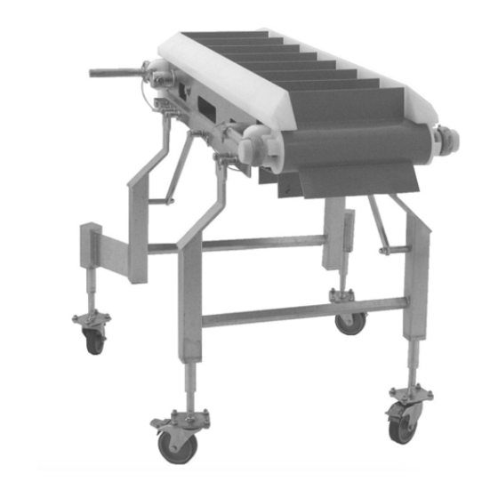
Page 4: Product Description
Product Description Refer to (Figure 1) for typical conveyor components. Typical Components Conveyor Belt (Flat Belt Shown) Return Support Stands Drive End Tension End Figure 1 7600 Ultimate Series CE End Drive Conveyors Dorner Mfg. Corp. 851-651 Rev. C... -
Page 5: Specifications
Cleat Spacing * Belt Material * Cleaning Options * Idler Stand Location * Drive/ Stand Location* Conveyor Length Reference * Conveyor Width Reference * Document Language * 7600 Ultimate Series CE End Drive Conveyors 851-651 Rev. C Dorner Mfg. Corp. -
Page 6: Conveyor Supports
• Non-accumulating product • Product moving toward gearmotor • Conveyor being mounted horizontally • Conveyor being located in a dry environment • Conveyor equipped with standard belt only 7600 Ultimate Series CE End Drive Conveyors Dorner Mfg. Corp. 851-651 Rev. C... -
Page 7: Installation
Installation Conveyors Longer than 3353 mm CAUTION (11 ft) CAUTION Dorner recommends cleaning all the “food zones” prior to placing conveyor into service. Belt and Frame Sections Ensure adequate access is provided for cleaning and servicing equipment so that the Typical Standard Belt (Figure 4). - Page 8 Figure 9 Align the sprockets (Figure 10, item 1) with the cogged drive teeth (Figure 10, item 2) on the inside of the belt. Figure 7 Figure 10 7600 Ultimate Series CE End Drive Conveyors Dorner Mfg. Corp. 851-651 Rev. C...
-
Page 9: Lpz Conveyors
(Figure 13, item 2) with hex rods (Figure 13, item 3) teeth on the inside of the belt. and bolts (Figure 13, item 4). Figure 16 Figure 13 7600 Ultimate Series CE End Drive Conveyors 851-651 Rev. C Dorner Mfg. Corp. -
Page 10: Guides
Repeat for opposite side of conveyor. (Figure 21, item 2) on the opposite side of the frame. Figure 21 Repeat the procedure for all other belt returns. 7600 Ultimate Series CE End Drive Conveyors Dorner Mfg. Corp. 851-651 Rev. C... -
Page 11: Cleated Belt
7 to remove slack from the belt. Up to 102 mm Figure 24 CAUTION CAUTION Belt sag should not exceed 102 mm from the top of the returns. 7600 Ultimate Series CE End Drive Conveyors 851-651 Rev. C Dorner Mfg. Corp. -
Page 12: Guide Installation
Insert the pull pins (Figure 32, item 1) into the holes in the guide (Figure 32, item 2). Figure 29 (Cleated Belt) Adjust limiter to within 1/32” from belt, and tighten screws (Figure 27, item 3). Figure 32 7600 Ultimate Series CE End Drive Conveyors Dorner Mfg. Corp. 851-651 Rev. C... -
Page 13: Stand Installation
• Some belt sag (Figure 37, item 1) is required for proper operation. Figure 34 Tighten hex screws (Figure 34, item 1). Figure 37 7600 Ultimate Series CE End Drive Conveyors 851-651 Rev. C Dorner Mfg. Corp. -
Page 14: Preventive Maintenance And Adjustment
LOCK OUT POWER before removing guards or performing maintenance. Exposed moving parts can cause serious injury. Dorner recommends cleaning the inside and the outside of the conveyor on a daily basis. Refer to the following steps to access the inside of the conveyor. -
Page 15: Periodic Cleaning
DO NOT submerge or soak bearing assemblies. This will reduce the life of the bearing. Periodic Cleaning Dorner recommends complete disassembly of the conveyor periodically for thorough cleaning. For conveyor disassembly and reassembly instructions: • Refer to “Conveyor Belt Replacement” on page 16. -
Page 16: Maintaining The Conveyor Belt
Preventive Maintenance and Adjustment Maintaining the Conveyor Belt Troubleshooting NOTE Visit www.dorner.com for complete list of troubleshooting solutions. Inspect conveyor belt for: • Surface cuts or wear • Skipping Damage to belt links or rods, surface cuts and / or... -
Page 17: Conveyor Belt Tensioning
(Figure 50, item 1). Figure 48 Secure the quick release arm on the stand and repeat steps 2 and 3 until the entire belt is off the conveyor. Figure 50 7600 Ultimate Series CE End Drive Conveyors 851-651 Rev. C Dorner Mfg. Corp. -
Page 18: Sprocket And Puck Removal
A - Drive Sprocket Removal WARNING PUNCTURE HAZARD! Handle drive shaft keyway with care. It may be sharp and could puncture the skin, causing serious injury. Figure 54 7600 Ultimate Series CE End Drive Conveyors Dorner Mfg. Corp. 851-651 Rev. C... - Page 19 Figure 56 Figure 58 Slide the motor support bracket (Figure 58, item 1) off the drive spindle (Figure 58, item 2). Remove the sprockets (Figure 58, item 3). 7600 Ultimate Series CE End Drive Conveyors 851-651 Rev. C Dorner Mfg. Corp.
-
Page 20: B - Idler Puck Removal
Use a hex wrench (Figure 61, item 1) to loosen the bearing shaft assembly fasteners (Figure 61, item 2). Figure 63 Remove the pucks (Figure 63, item 2). Figure 61 7600 Ultimate Series CE End Drive Conveyors Dorner Mfg. Corp. 851-651 Rev. C... -
Page 21: Reassembling Tail Assemblies
(Figure 65, item 3) and the bearing shaft assemblies (Figure 65, item 1) onto the idler shaft (Figure 65, item 2). Figure 67 Attach the bearing covers. Reference (Figure 60). Figure 65 7600 Ultimate Series CE End Drive Conveyors 851-651 Rev. C Dorner Mfg. Corp. -
Page 22: Drive Tail
(Figure 69, item 3). Position the first sprocket with the notch in the sprocket alignment bar. Figure 71 Install washer (Figure 72, item 1) onto spindle shaft. Figure 69 Figure 72 7600 Ultimate Series CE End Drive Conveyors Dorner Mfg. Corp. 851-651 Rev. C... -
Page 23: Bearing Replacement
10. Attach the guard bar (Figure 75, item 1) to the bearing / motor mount bracket shafts Figure 77 (Figure 75, item 2). Apply lateral pressure to the rod until the bearing comes loose. Figure 75 7600 Ultimate Series CE End Drive Conveyors 851-651 Rev. C Dorner Mfg. Corp. -
Page 24: Lpz Knuckles
Use a hex wrench to loosen the bearing shaft assembly fasteners (Figure 80, item 2). Slide the bearing flange assembly (Figure 80, item 3), off the spindle shaft end (Figure 80, item 4). 7600 Ultimate Series CE End Drive Conveyors Dorner Mfg. Corp. 851-651 Rev. C... -
Page 25: Installation
Figure 84 available notch in the sprocket alignment bar. Secure sprockets in place with bolt (Figure 82, item 4). 7600 Ultimate Series CE End Drive Conveyors 851-651 Rev. C Dorner Mfg. Corp. -
Page 26: Service Parts
Service Parts Service Parts NOTE For replacement parts other than those shown in this section, contact an authorized Dorner Service Center or the factory. Key Service Parts and Kits are identified by the Performance Parts Kits logo . Dorner recommends keeping these parts on hand. - Page 27 (Includes Items 1, 3, 4, 10, 11, 14, 17 and 18) WW = Conveyor width ref: 06 - 36 in 02 increments * When the conveyor is ordered with a Dorner gearmotor mounting package the shaft assembly is replaced with a gearmotor mounting bracket.
-
Page 28: Tension End
Pinch Guard Shaft 76UIT-WW Idler Tail Kit (Includes items 1 501381 Washer through 10, 13 and 14) WW = Conveyor width ref: 06 - 36 in 02 increments 7600 Ultimate Series CE End Drive Conveyors Dorner Mfg. Corp. 851-651 Rev. C... -
Page 29: Conveyor Frame And Extension
Straight Wear Strip 501190 Hex Post Connector 961016MSS Hex Head Cap Screw M10-1.5 x 16mm 807-1616 O-Ring LLL = Conveyor length ref: 036 - 999 in 001 increments 7600 Ultimate Series CE End Drive Conveyors 851-651 Rev. C Dorner Mfg. Corp. -
Page 30: Upper Knuckle For Flat Belt Conveyors
WW = Conveyor width ref: 06 - 24 in 02 increments Right Hand AA = Angle 05, 10 or 15 501984-AA Hold Down Guide for Knuckle - Left Hand 7600 Ultimate Series CE End Drive Conveyors Dorner Mfg. Corp. 851-651 Rev. C... -
Page 31: Upper Knuckle For Cleated Belt Conveyors
2, 3, 4, 8, 9, 12 and 13) 807-1616 O-Ring WW = Conveyor width ref: 06 - 24 in 02 increments 807-1445 Sprocket AA = Angle 30, 45 or 60 5164WW Sprocket Alignment Bar 7600 Ultimate Series CE End Drive Conveyors 851-651 Rev. C Dorner Mfg. Corp. -
Page 32: Lower Knuckle For Cleated Belt Conveyors
Wear Strip 74LK-WW-AA Lower Knuckle Kit (Includes Item 2) WW = Conveyor width ref: 06 - 24 in 02 increments AA = Angle 30, 45 or 60 7600 Ultimate Series CE End Drive Conveyors Dorner Mfg. Corp. 851-651 Rev. C... -
Page 33: 76 Mm High Sides
LLLLL = Guide Length in inches with 2 decimal places. 503601- Left Hand High Side Guide LLLLL Example: Guide Length = 95.25" LLLLL = 09525 501676 Pin Assembly 7600 Ultimate Series CE End Drive Conveyors 851-651 Rev. C Dorner Mfg. Corp. -
Page 34: Cleated 25 Mm Guides
LLLLL = Guide Length in inches with 2 decimal places. 502502-LLLLL 25 mm Cleated Left Hand Guide Example: Guide Length = 95.25" LLLLL = 09525 (18" - 24" wide conveyors) 7600 Ultimate Series CE End Drive Conveyors Dorner Mfg. Corp. 851-651 Rev. C... -
Page 35: Cleated 76 Mm Guides
LLLLL = Guide Length in inches with 2 decimal places. 502802- 76 mm Cleated Left Hand Guide Example: Guide Length = 95.25" LLLLL = 09525 LLLLL (18" - 24" wide conveyors) 7600 Ultimate Series CE End Drive Conveyors 851-651 Rev. C Dorner Mfg. Corp. -
Page 36: Flat Belt Returns
500195 Belt Lifter 500491 Belt Lifter Handle 960812MSS Hex Head Cap Screw M8-1.25 x 12 mm WW = Conveyor width ref: 06 - 36 in 02 increments 7600 Ultimate Series CE End Drive Conveyors Dorner Mfg. Corp. 851-651 Rev. C... -
Page 37: Service Parts
01 cleated belt material, side drive with standard pulleys on drive with standard pulleys on each end, low side profiles, each end, and 10”spacing for cleats. and 01 belt material. 7600 Ultimate Series CE End Drive Conveyors 851-651 Rev. C Dorner Mfg. Corp. -
Page 38: Return Policy
A representative will discuss action to be taken on the returned items and provide a Returned Goods Authorization number for reference. There will be a return charge on all new undamaged items returned for credit where Dorner was not at fault. Dorner is not responsible for return freight on such items.
Need help?
Do you have a question about the AquaPruf ULTIMATE 7600 Series and is the answer not in the manual?
Questions and answers