Table of Contents
Advertisement
Available languages
Available languages
Quick Links
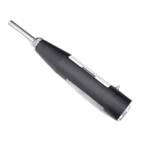
CONCRETE STRENGTH TESTER
Beton
EN
User manual
Congratulations on your purchase of concrete strength tester Beton
CONDTROL. The user manual contains basic information about the device,
its operating principle, technical specifications and other information
about concrete strength tester Beton CONDTROL (hereinafter referred to
as the sclerometer) that are necessary for normal operation of sclerometer.
1. FUNCTIONS/APPLICATIONS
1.1 Sclerometer is designed to determine the strength of concrete in
concrete and reinforced concrete structures and products by the rebound
method.
1.2 The operating principle of the sclerometer is based on normalized
energy impact of the striker on the concrete surface and measurement of
the rebound height in conventional units of the device scale. This height is
an indirect characteristic of the compressive strength of concrete.
The strength of concrete is determined by calibration dependencies
between the rebound height and the compressive strength of concrete.
They are established by parallel testing of control concrete cubes with a
sclerometer and a press.
1.3 The sclerometer is refurbished repairable product and can be used
indoors and outdoors.
2. TECHNICAL SPECIFICATIONS
Measuring range
10-60 MPa
Relative accuracy
20%
Scale value
2 units
Impact energy
>1,8 J
Spring compression force
70 N
Variation of readings when measuring
±2 units (one mark on a scale)
rebound height on steel-anvil
Hardness of flip road and impact hammer
НRС 59—63
working surfaces
Spherical radius of flip rod
(25±5) mm
-50°C...+400°C, when relative
Operating temperature
humidity
80%
condensation
Dimensions
280x75x60 cm
Weight
1,1 kg
Mean value of steel-anvil readings of
80±2 units
sclerometer
3. DELIVERY PACKAGE
Concrete strength tester Beton CONDTROL – 1 pc.
Grinding stone -1 pc.
Screwdriver – 1 pc.
Spring – 1 pc.
User manual – 1 pc.
Plastic case – 1 pc.
4. STRUCTURE AND OPERATING PRINCIPLE
The housing of sclerometer (3) consisting of cylindrical and conical parts
has a spring impact mechanism installed inside of it. It includes a flip rod
(1), collet (8), impact hammer (14), hanger dowel (24) and a hanger (13),
flip tension spring (16), pressure spring (12), buffer pressure spring (15)
and sclerometer readings datum node in the form of pointer block (4) that
is moving along the diving rule (5) on a pointer shaft (22) and serves to fix
the height of the impact hammer rebound.
Push button (6) built into the housing is used to fix the position of the hanger
dowel after an impact (so that the hanger dowel did not return the pointer
block to its original state).
A bolt (19) is screwed into the cover from the inside, serving to adjust the
impact hammer height.
A cap (9) is screwed onto the front end of the conical part of the housing.
and
no
With the help of two clasps (10) the cap pinches the tension spring seat
(17) through which the indenter lies, sliding along the central guide rod (7).
The tension spring seat has a helical groove with holes for mounting and
adjustment of the working spring front end tension. Its rear part is fixed on
the neck of the impact hammer.
A collet is located at the front end of the central guide rod on which the
indenter is put on, and on the back - the hanger dowel. A hanger is fixed on its
axis, which serves to hold the impact hammer when sclerometer is activated.
The pivot end of the hanger is spring-loaded.
To prepare the sclerometer for operation, press slightly the flip rod. The
hanger dowel will move up, free from push button. Because of the pressure
spring, the flip rod will move until the hanger will be held by impact hammer.
The hanger dowel will return the pointer block to zero on the scale.
During operation, the sclerometer flip rod is placed on the concrete surface,
the housing is moved to it along the flip rod. At the same time, the flip tension
spring is stretched and charged by a pre-shock energy. The bolt moves in the
direction of a hanger. So that to protect the pointer block form the impact
hammer when the sclerometer is activated, the hanger dowel holder keyways
slide over the keyways guides attached from the inside to the cylindrical part
of the housing with a slight slope, and bypasses the pointer block.
When the bolt hits the hanger dowel, it turns on the axis of the pin and
releases the impact hammer. With the help of the flip tension spring, the
impact hammer strikes the flip rod and then it hits the surface through it. Due
to the elasticity of concrete, the striker bounces, moving upwards it holds a
pointer block and moves in along the scale.
The damper spring isolates the collet from impact reaction.
When moving the sclerometer away from the surface, the pressure spring will
start pushing out the flip rod for the next windup. The sclerometer will return
to its original state (flip rod extended, pointer block at zero).
To fix the position of the pointer block, it is necessary to press the push
button after the impact and while holding the button, take sclerometer away
from the surface.
1 - Flip rod
2 - Test surface
3 - Housing
4 - Pointer block
5 - Dividing rule
6 - Push button
Flip rod
7 - Center guide rod
8 - Collet
9 - Cap
Cap
10 - Clasp
11 - Tail hood
12 - Pressure spring
Housing
13 - Hanger
14 - Impact hammer
15 - Buffer pressure spring
16 - Flip tension spring
17 - Tension spring seat
5. SAFETY REGULATIONS
5.1 Do not let unauthorized people enter the zone of product operation.
18 - Felt ring
5.2 Do not work with the sclerometer on straight ladders
19 - Bolt
5.3 Do not activate flip tension spring when carrying and storing the
20 - Nut
sclerometer. It is recommended to fix the push button in the pressed position
21 - Pointer piece
with adhesive tape when transporting the sclerometer.
22 - Pointer shaft
6. BEFORE START OPERATION
6.1 Take the sclerometer from the case.
23 - Hanger spring
6.2 Short press the spherical end of the flip rod with a finger (palm) to bring
24 - Hanger dowel
the sclerometer to its original position (flip rod extended, the pointer block at
the zero mark of the scale). At the same time, the pointer block should be on
the zero mark of the scale with an accuracy of two units (one mark).
6.3 Install the sclerometer in the steel-anvil sleeve perpendicular to the base,
making sure that the deviation from the straight line angle doesn't not exceed
4 mm at a distance of 100 mm. Holding the housing of sclerometer with both
hands so that one finger is at the push button, press the flip rod against the
surface of the anvil punch and smoothly move the housing to the base of
the anvil until it clicks (impact). Hold it for 3 seconds without removing the
sclerometer from the surface of the punch anvil, press the push button with
your finger and take the sclerometer away from the surface keeping the
button pressed.
ATTENTION! Do not press or hold the push button while measurement
(impact), it may damage the sclerometer.
Remove the sclerometer from the anvil sleeve and determine on the scale the
rebound height with an accuracy of one (0.5 scale divisions).
6.4 Make 4 more measurements in accordance with paragraphs 6.2-6.3.
Readings of the device should be within 80 ± 2 units.
Instead of an anvil, a test surface with known strength can be used. At the
same time, the readings of the sclerometer should match the strength of the
sample. The choice of test surface should comply with clause 7.2.
If the above requirements are not met, check and adjust the sclerometer in
accordance with section 8 of this user manual.
7. OPERATION
7.1 Concrete strength can be controlled by testing of control samples with a
size of at least 100x100x100 mm, or according to the results of determining
the strength of concrete in products and structures.
7.2 Choose the test sites on the product.
7.2.1 Tests must be carried out on a flat area without potholes and bulges.
If necessary, prepare the surface with grinding stone. The size of the site is
not less than 100 cm
of the product, with a thickness not less than 50 mm.
2
When determining the strength of concrete of the examined structures,
there should be at least 3 controlled sites.
The boundary of the site should be no closer than 50 mm from the edge of
the structure. The distance between the test spots should be at least 15 mm.
The distance of the test sites to the reinforcement should be not less than 50
mm. Use the rebar locator to find valve positions.
7.2.2 When determining the strength of concrete with samples, tests are
carried out on the side surfaces of the samples. At the same time, the samples
must be clamped in the press with a force of 30 kN. Choice of test site on
samples must be carried out in accordance with clause 7.2.1.
7.3 The number of tests on the site should be sufficient to obtain reliable data
after averaging the measurement results.
7.3 Bring the sclerometer to its original position according to the
instructions in clause 6.2.
7.4 Install the sclerometer at the selected point of the test surface (the
position of the sclerometer must correspond to one of those indicated in
Calibration table
the conversion table). Make a strike according to the instructions in clause
6.3, then determine the rebound height on the scale and record it in the
test sheet.
Continue testing at other points of the product.
Push button
7.5 Processing of the obtained results should be carried out considering the
position of the sclerometer during measurements. Possible positions of the
device are listed in the conversion table.
Cover
The average strength of concrete is taken as a single value, defined as the
arithmetic mean of the concrete strength in the controlled site.
ATTENTION! Every day before measuring, check the proper operation of
the sclerometer according to the requirements of chapter 6.
8. CARE AND MAINTENANCE
8.1 The worker servicing the sclerometer must be qualified in accordance
with clause 5.1.
8.2 Maintenance is carried out after a long use (20,000 strokes) or if
Datum node
accuracy exceeds the declared one, but not less than once every six months
before the beginning of work in the scope and sequence given in table.
What to check and checking procedure
1. No contamination of sclerometer
parts and damage of the percussion
mechanism parts.
Carry out checking according to
clause 8.3-8.6.
2. Operational check of the sclerometer.
8.3 Before checking according to clause 1 of Table 8.1 sclerometer should
be disassembled. Disassembly is carried out in the following order. Remove
the flip rod and remove the buffer pressure spring from it. Unscrew the cap
and remove the clasps. Hold the sclerometer with one hand in a horizontal
position with the scale up, unscrew the cover with the other hand. Carefully
remove the pressure spring. Hold the hanger with two fingers, slowly pull it
toward, moving the hanger dowel along the guide.
When the hanger dowel runs off the guides, turn it up to a position at which
the entire withdrawn node of the percussion mechanism can be carefully
removed from the case. At the same time, it is extremely important not hit
the pointer block.
Press on the spring connecting the hanger with the hanger dowel, releasing
the impact hammer from a hanger. Remove the impact hammer with the
flip tension spring from the collet.
Unscrew and remove the shaft from the housing. Remove the pointer block
from the housing.
8.4 Inspect the parts of the impact mechanism to make sure in the absence
of chips on the colliding surfaces of the impact hammer and the flip rod. If
chips are found, send the sclerometer to a service center.
8.5 Wipe the housing from the inside and all parts of the sclerometer with a
soft cloth lightly dampened with petrol or mineral spirits, wipe the flip rod
hole with gasoline using a soft cloth. Wipe the collet with liquid oil. Grease
the buffer pressure spring and collet shutters with saline.
8.6 Assemble the sclerometer in the reverse order of disassembly.
8.7 If during the control according to clause 2 of the table. 8.1. the specified
requirements are not met, it is necessary to adjust the sclerometer. The
following cases may take place:
1) the pointer lock begins to move along the pointer shaft when the
sclerometer is activated;
2) the pointer lock does not move during an impact;
3) the reading of the sclerometer when striking on the steel anvil does not
meet the requirements of clause 6.
Depending on the nature of the deviation, adjustment should be carried
out in the following order:
8.7.1 Perform disassembly according to clause 8.3. and remove the pointer
shaft with a pointer lock from the housing.
8.7.2 If cases 1 or 2 take place (see clause 8.7), change the bend of the front
wing of the pointer lock carefully, reducing it in case 1 or increasing it in
case 2.
Assemble the sclerometer and carry out a check according to paragraphs
6.2-6.4. As a rule, 2 or 3 attempts are enough for the final adjustment.
Technical requirements
The instrument must comply
with clauses 8.3-8.6.
The instrument must comply
with clause 6.
Advertisement
Table of Contents

Subscribe to Our Youtube Channel
Related Manuals for CONDTROL Beton


Summary of Contents for CONDTROL Beton
- Page 1 6 - Push button Continue testing at other points of the product. Flip rod Congratulations on your purchase of concrete strength tester Beton 7 - Center guide rod Push button 7.5 Processing of the obtained results should be carried out considering the CONDTROL.
-
Page 2: Possible Malfunctions And Solutions
6) After holding warranty works by CONDTROL GmbH warranty period is not renewed or extended. 7) CONDTROL GmbH is not liable for loss of profit or inconvenience associated with a defect of the device, the rental cost of alternative equipment for the period of repair. -
Page 3: Betrieb
Betonfestigkeit wird durch die voreingestellten Umwertungskurven 16 – Schlagfeder; Umrechnungstabelle gegebenen Position, übereinstimmen), gemäß zwischen der Rückprallhöhe und der Druckfestigkeit von Beton, die im dem Punkt 6.3 einen Schlag versetzen, nach der Skala die Rückprallhöhe Voraus durch parallele Tests der Probewürfel mit dem Betonprüfhammer 17 –... -
Page 4: Wartung Und Reparatur
7) Die CONDTROL GmbH übernimmt keine Verantwortung für Gewinnverlust und andere Umstände, die mit dem defekten Gerät in Verbindung stehen. Die CONDTROL GmbH übernimmt keine Kosten für Miet- oder Leihgeräte während der Reparatur. Für die Garantie gilt deutsches Recht. Ausgeschlossen ist das CISG... -
Page 5: Description Générale
Si vous souhaitez de mesurer une surface courbe, le rayon laissez pas l’humidité, la poussière de construction, les corps étrangers 4) CONDTROL GmbH se réserve le droit de décider du remplacement ou de de courbure ne doit pas être inférieur à 23 cm. - Page 6 Приложение А. Приложение А. Приложение А. Приложение А. Приложение А. Annexe A Évaluation des résultats de mesure. Таблица зависимости между высотой отскока, направлением удара и прочностью бетона Таблица зависимости между высотой отскока, направлением удара и прочностью бетона Таблица зависимости между высотой отскока, направлением удара и прочностью бетона Таблица...
-
Page 7: Garanzia
Il numero di misure ideale è 16. contattare un centro di assistenza. 6) Dopo che CONDTROL GmbH ha eseguito i lavori di garanzia, il periodo di Spessore del cemento massimo 70 cm - Non conservare e non utilizzare il dispositivo per lunghi periodi in ambienti garanzia non viene esteso. - Page 8 Приложение А. Приложение А. Приложение А. Приложение А. Приложение А. Appendice А Valutazione dei risultati della misura. Таблица зависимости между высотой отскока, направлением удара и прочностью бетона Таблица зависимости между высотой отскока, направлением удара и прочностью бетона Таблица зависимости между высотой отскока, направлением удара и прочностью бетона Таблица...
-
Page 9: Технические Характеристики
6 - кнопка стопор; измерения. устройстве, принципе действия, технических характеристиках и 7 - центральный стержень; 7.3 Привести склерометр в исходное положение согласно указаниям др. сведения о измерителе прочности бетона Beton CONDTROL п.6.2. 8 - цанга; (далее склерометр), необходимые для нормальной эксплуатации индентор... -
Page 10: Возможные Неисправности И Способы Их Устранения
Неисправные или пришедшие в негодность аккумуляторы/батареи должны быть утилизированы согласно Директиве 2006/66/ЕС. Производитель оставляет за собой право вносить изменения в конструкцию, алгоритмы работы, комплектацию прибора без предварительного уведомления. 12. СЕРВИС И КОНСУЛЬТАЦИОННЫЕ УСЛУГИ Контакты для связи, консультации можно получить на сайте www.condtrol.ru.
Need help?
Do you have a question about the Beton and is the answer not in the manual?
Questions and answers