
Subscribe to Our Youtube Channel
Related Manuals for Check Point Power-1 P-10


Summary of Contents for Check Point Power-1 P-10
- Page 1 Power-1 Getting Started Guide Models: P-10, P-20, P-30 3 July 2012 Classification: [Protected] | P/N: 704885...
- Page 2 Check Point. While every precaution has been taken in the preparation of this book, Check Point assumes no responsibility for errors or omissions. This publication and features described herein are subject to change without notice.
-
Page 3: Important Information
Added Gaia to Restoring Using the WebUI (on page 43) 26 August 2010 Initial version Feedback Check Point is engaged in a continuous effort to improve its documentation. Please help us by sending your comments (mailto:cp_techpub_feedback@checkpoint.com?subject=Feedback on Power-1 Getting Started... -
Page 4: Health And Safety Information
Health and Safety Information Health and Safety Information Read the following warnings before setting up or using the appliance. Warning - Do not block air vents. A minimum 1/2-inch clearance is required. Warning - This appliance does not contain any user-serviceable parts. Do not remove any covers or attempt to gain access to the inside of the product. - Page 5 Health and Safety Information Do not operate the processor without a thermal solution. Damage to the processor can occur in seconds. For California: Perchlorate Material - special handling may apply. See http://www.dtsc.ca.gov/hazardouswaste/perchlorate The foregoing notice is provided in accordance with California Code of Regulations Title 22, Division 4.5, Chapter 33.
- Page 6 Health and Safety Information Japan Class A Compliance Statement: European Union (EU) Electromagnetic Compatibility Directive This product is herewith confirmed to comply with the requirements set out in the Council Directive on the Approximation of the Laws of the Member States relating to Electromagnetic Compatibility Directive (2004/108/EC).
-
Page 7: Table Of Contents
Contents Important Information ..................... 3 Health and Safety Information ................4 Introduction ......................9 Welcome ......................9 Power-1 Overview ....................9 This document provides: ................10 Shipping Carton Contents...................10 Terminology......................10 Configuring Power-1 ..................... 13 Mounting Power-1 in a Rack ................14 Connecting the Power Cables and Power On .............14 Available Software Images .................15 Initial Configuration .....................15 Using the First Time Configuration Wizard on Gaia ..........17... - Page 8 Advanced Configuration ..................26 Connecting to the Power-1 CLI ..............26 Power-1 Hardware ....................27 Front Panel Components ..................27 Power-1 11000 Series Front Panel ..............27 Power-1 9070 Front Panel ................28 Power-1 5070 Front Panel ................29 Managing Power-1 Using the LCD Panel ............30 Expansion Line Cards ..................
-
Page 9: Introduction
Point Web site (http://www.checkpoint.com), or call Check Point at 1(800) 429-4391. For more technical information about Check Point products, consult the Check Point Support Center (http://supportcenter.checkpoint.com). Welcome to the Check Point family. We look forward to meeting all of your current and future network, application and management security needs. Power-1 Overview The family of Power-1 appliances enables organizations to maximize security in high- performance environments such as large campuses or data centers. -
Page 10: This Document Provides
Introduction Proven, enterprise-class firewall, VPN, and intrusion prevention Accelerated security performance, including SecureXL and CoreXL technologies Integrated load balancing and dynamic routing for data center reliability levels Centrally managed from Security Management Server/Power-1 Automatic security protection updates from SmartDefense Services This document provides: ... - Page 11 Locally Managed Deployment: When all Check Point components responsible for both the management and enforcement of the security policy (the Security Management Server and the gateway) are installed on the same machine.
-
Page 13: Configuring Power-1
Chapter 2 Configuring Power-1 In This Chapter Mounting Power-1 in a Rack Connecting the Power Cables and Power On Available Software Images Initial Configuration Using the First Time Configuration Wizard on Gaia Using the First Time Configuration Wizard on SecurePlatform Creating the Network Object Advanced Configuration The workflow for configuring Power-1 is:... -
Page 14: Mounting Power-1 In A Rack
Configuring Power-1 Mounting Power-1 in a Rack Mount the system in the rack with the network ports facing the front of the rack. Connecting the Power Cables and Power On 1. Connect the power cables. 2. On the back panel, turn on the Power button to start the appliance. Note - When a power supply fails or is not connected to the outlet, an alarm sounds continuously. -
Page 15: Available Software Images
Configuring Power-1 3. Wait for the appliance to initialize and boot. The status of the appliance appears on the LCD screen: The appliance is ready for use when the model number is displayed. Available Software Images Power-1 comes with multiple software images. Select the software image that you want to use. Reverting to a software image takes a few minutes. - Page 16 Configuring Power-1 Go to the applicable section: Using the First Time Configuration Wizard on Gaia (on page 17) Using the First Time Configuration Wizard on SecurePlatform (on page 22) 16 | Power-1 Getting Started Guide...
-
Page 17: Using The First Time Configuration Wizard On Gaia
Configuring Power-1 Using the First Time Configuration Wizard on Gaia Use the First Time Configuration Wizard to do the initial configuration of the Gaia appliance. Note - The pages that you see in the wizard depend on the software image and the options you select. You will not see all the pages that are in this section. -
Page 18: Available Releases
Configuring Power-1 Available Releases The appliance comes with different software images. Select the software image that you want to install. You can change to another software image after the First Time Configuration Wizard is completed. If you select a SecurePlatform software image, use the SecurePlatform First Time Configuration Wizard to configure the appliance. -
Page 19: Network Connection
Configuring Power-1 Network Connection Connection Information - Configure the IPv4 interface information for the management interface. You can change the Management IP address. Connectivity is maintained with an automatically created secondary interface. After you complete the First Time Configuration Wizard, you can remove this interface in the Interface Management > Network Interfaces page. -
Page 20: Security Management Administrator
Configuring Power-1 ClusterXL - For more about ClusterXL configurations, see the applicable version of the ClusterXL Administration Guide. VRRP - For more about VRRP clusters, see the applicable version of the Gaia Administration Guide. Define Security Management as - In a Management High Availability deployment, define this Security Management server as Primary or Secondary. -
Page 21: Dynamically Assigned Ip
Configuring Power-1 Define the clients that are allowed to connect to the appliance using a web browser or SSH client. These clients can manage the appliance using a web or SSH connection. For security reasons, we recommend that you do not use the Any IP address option. Dynamically Assigned IP Note - You see this page when the appliance is a Security Gateway. -
Page 22: Using The First Time Configuration Wizard On Secureplatform
Configuring Power-1 Using the First Time Configuration Wizard on SecurePlatform Do the initial configuration of the SecurePlatform appliance with the First Time Configuration Wizard. Note - The pages that you see in the wizard depend on the software image and the options you select. You will not see all the pages that are in this section. -
Page 23: Welcome
Configuring Power-1 6. The First Time Configuration Wizard runs. Welcome The Welcome page summarizes the steps of the First Time Configuration Wizard. Appliance Date and Time Setup Configure date and time in the Date and Time Setup page. Click Apply. Network Connections Configure the network connections in the Network Connections page. -
Page 24: Management Type
Secondary cluster member For information about clusters, see the ClusterXL Administration Guide (http://supportcenter.checkpoint.com) for your Check Point version. Web/SSH and GUI Clients Configuration Define the clients that are allowed to connect to the appliance using a web browser or SSH client. -
Page 25: Summary
Configuring Power-1 The release notes of your Check Point version in the Check Point Support Center (http://supportcenter.checkpoint.com), lists compatible Windows operating systems for SmartConsole. Centrally Managed Deployment This section describes how to configure the appliance for centrally managed deployment. Gateway Type Configure the gateway type for a Centrally Managed Power-1. -
Page 26: Creating The Network Object
Configuring Power-1 Creating the Network Object Configure the Power-1 object as a gateway object in the Security Management server database. 1. Launch SmartDashboard. 2. Configure a new gateway object for the appliance. 3. Enter the IP address for the appliance. 4. -
Page 27: Power-1 Hardware
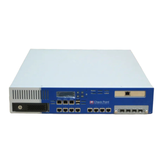
Chapter 3 Power-1 Hardware In This Chapter Front Panel Components Rear Panel Components Customer Replaceable Parts This chapter provides instructions for installing and removing hardware components on the Power-1 appliance. Front Panel Components This section describes the features and components located on the appliance front panel. Power-1 11000 Series Front Panel Key Description LCD display screen... -
Page 28: Power-1 9070 Front Panel
Power-1 Hardware Key Description Synchronization port - for synchronizing with cluster members or a high availability peer Console port - for a serial connection to the appliance using a terminal emulation program such as HyperTerminal Keypad Power indicator LED USB ports Future expansion slot Expansion line card exp1 (2 or 4 ports) Built in Ethernet ports (Lan1 - Lan8) -
Page 29: Power-1 5070 Front Panel
Power-1 Hardware Key Description Management connection port - Ethernet connection to a remote management workstation Synchronization port - for synchronizing with cluster members or a high availability peer Console port - for a serial connection to the appliance using a terminal emulation program such as HyperTerminal Screen operation keys Power indicator LED... -
Page 30: Managing Power-1 Using The Lcd Panel
Power-1 Hardware Key Description LCD display screen Management connection port - Ethernet connection to a remote management workstation Synchronization port - for synchronizing with cluster members or a high availability peer Console port - for a serial connection to the appliance using a terminal emulation program such as HyperTerminal Screen operation keys Power indicator LED... - Page 31 Power-1 Hardware Menu Sub-menu Purpose Set Internal IP Set the management interface IP address (cannot be edited when DHCP is Set Mgmt IP enabled) Set Netmask Set the management interface network mask (cannot be edited when DHCP is enabled) Set Default GW Set the management interface default gateway (cannot be edited when DHCP is enabled)
-
Page 32: Expansion Line Cards
Power-1 Hardware Press Approve the change when the cursor is located on the last digit Cancel the IP change when the cursor is located on the first digit Change current digit Expansion Line Cards The Power-1 appliance contains optional expansion slots that accommodate cold-swappable network line cards. -
Page 33: Rear Panel Components
Power-1 Hardware Power-1 9070 and 11000 series models contain two hot-swappable redundant hard disk drives (RAID1). RAID1 Mirroring Implemented by a dedicated RAID controller, the Power-1 9070 model performs RAID1 mirroring across two hard disk drives. Mirror rebuild is automatic. Rear Panel Components This section describes components located on the rear panel of the appliance. -
Page 34: Main Power Switch
Power-1 Hardware Main Power Switch The main power switch controls power to the entire unit. This appliance has two main power switches for your convenience. Redundant Power Supply Units Located at the right rear of the appliance, two hot-swappable power supply units provide built-in power redundancy. -
Page 35: Customer Replaceable Parts
Power-1 Hardware Customer Replaceable Parts For maximum availability and easy maintenance, the appliance has many customer replaceable parts. Power-1 5070 Power-1 9070 Power-1 11000 Series Power supplies Cooling fans Expansion line 1 with additional slot 1 with additional slot cards Hard disk drives 2 (RAID-1) Hot 2 (RAID-1) Hot... -
Page 36: Power Supply
Power-1 Hardware Unless directed to do so by Check Point technical support, customers are prohibited by warranty and support agreements from replacing any parts. Customers are prohibited from opening the Power-1 case under any circumstances. Power Supply This section presents the procedures for removing and installing a power supply unit. Power-1 appliance contains two redundant power supplies. -
Page 37: Cooling Fan
Power-1 Hardware Note - Use only the extraction handle to remove the power supply unit. To prevent damaging the power supply, do not pull on the retaining screw, power cord clip or any other part of the unit. Installing the Power Supply To install a replacement power supply: 1. -
Page 38: Expansion Line Card
Power-1 Hardware Removing Fan Units To remove a fan unit: 1. Loosen the four retaining screws in the corners of the fan assembly. 2. Gently pull the fan unit out of the appliance. Installing Fan Units To install a fan unit: 1. -
Page 39: Hard Disk Drive
Power-1 Hardware Removing Expansion Line Cards To remove an expansion line card: 1. Power off the appliance and remove the power cords from the power supply units. 2. Loosen the retaining screws on either side of the expansion line card. 3. - Page 40 Power-1 Hardware Power-1 5070 Power-1 9070 Power-1 11000 Series Hard disk drives 2 (RAID-1) 2 (RAID-1) Hot swappable Hot swappable Removing a Hard Disk Drive To remove a hard disk drive: 1. Power-1 5070 only: Hard disk drive is not hot-swappable. Turn off the appliance and remove the power cords from the power supply unit before attempting to remove the hard disk drive.
- Page 41 Power-1 Hardware Installing a Hard Disk Drive To install a hard disk drive: 1. Power-1 5070 only: Hard disk drive is not hot-swappable. Turn off the appliance and remove the power cords from the power supply unit before attempting to remove the hard disk drive.
-
Page 43: Restoring Factory Defaults
Chapter 4 Restoring Factory Defaults In This Chapter Restoring Using the WebUI Restoring Using the Console Boot Menu Restoring Using the LCD Panel If necessary, restore the appliance to its factory default settings. Important - If you restore factory defaults, all information on the appliance is deleted. -
Page 44: Secureplatform
Restoring Factory Defaults SecurePlatform Use the SecurePlatform WebUI to restore the default factory settings. To restore a SecurePlatform appliance with the WebUI: 1. Open Internet Explorer and navigate to the management IP address, https://<appliance_ip_address>:4434 2. Log in to the WebUI of the appliance using the administrator username and password. 3. -
Page 45: Restoring Using The Lcd Panel
Restoring Factory Defaults 8. The appliance initializes and status messages are shown in the terminal emulation program. 9. When this message is shown, you have approximately four seconds to hit any key to activate the Boot menu. 10. From the Boot menu, select the relevant Reset to factory defaults image. 11. - Page 46 Restoring Factory Defaults 4. Press 5. Confirm the reset by pressing Pressing any other button causes the Action Canceled message to display: At this point, pressing any key returns you to the boot menu. 6. Once you have confirmed the reset, wait for the appliance to restore the factory image. While the appliance is restored to the default image, a Reverting image don't turn off message displays continuously.
-
Page 47: Registration And Support
You have the basics to get started. The next step is to get more advanced knowledge of your Check Point software. Check Point documentation is available on the Check Point Support Center (http://supportcenter.checkpoint.com). Be sure to also use the Online Help when you are working with the Check Point SmartConsole clients. Power-1 Getting Started Guide | 47...
Need help?
Do you have a question about the Power-1 P-10 and is the answer not in the manual?
Questions and answers