Table of Contents
Advertisement
Quick Links
Advertisement
Table of Contents

Related Manuals for Delta OHM DO 9721


Summary of Contents for Delta OHM DO 9721
- Page 1 DO 9721 INSTRUCTIONS MANUAL...
- Page 2 DO 9721...
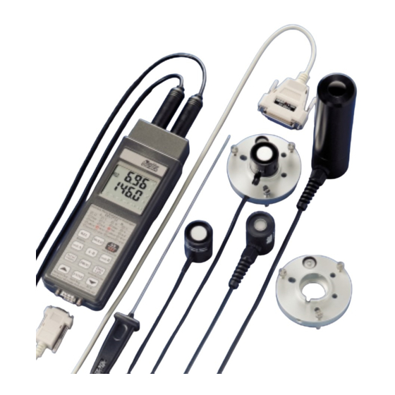
- Page 3 DO 9721 QUANTUM-PHOTO RADIOMETER AND THERMOMETER DATA-LOGGER...
- Page 4 ENGLISH 1 Input A, DIN 45326 8-pole connector. 2 HOLD symbol, the measurement refers to the moment in which the HOLD key was pressed. 3 Battery symbol: flashes during RECORD function, permanently lit if the battery is running low 4 REL symbol, indicates that the instrument is making a relative measurement. 5 Serial Out/Memory.
-
Page 5: Introduction
As the probes are interchangeable, it is possible to choose the most suitable combination for all applications without having to recalibrate the instrument. The DO 9721 is able to take illuminance measurements in lux and in fcd (foot-candle), irradiance measurements in W/m , in µW/cm... -
Page 6: Keyboard Description
ENGLISH KEYBOARD DESCRIPTION SIMBOLS LIT BESIDES FUNCTION THE NUMBERS DESCRIPTION ON/OFF All the symbols are lit for a few ON/OFF key. Press this key seconds after pressing the repeatedly to switch the instru- ON/OFF key. ment on or off. Complete display. The instrument has a cut-out system (Auto Power Off) which switches off automatically after... - Page 7 ENGLISH SIMBOLS LIT BESIDES FUNCTION THE NUMBERS DESCRIPTION The REL key allows you to display or store relative values or send them immediately onto the serial line. The values for compa- rison are stored at the precise moment in which the key is pres- sed.
- Page 8 ENGLISH SIMBOLS LIT BESIDES FUNCTION THE NUMBERS DESCRIPTION UNIT B For channel B, this fulfils a similar function to unit A; it is presented at the bottom of the display. Pressing A-B obtains, at the bot- tom of the display, the difference between the value at input A and the one at input B.
- Page 9 ENGLISH SIMBOLS LIT BESIDES FUNCTION THE NUMBERS DESCRIPTION - P0 - When ENTER is pressed with P0 on the display, the instrument returns to normal operating mode without storing any parameter. Press the PROG key to move on to step P1. When unit A or unit B is pressed with P0 on the display, it gives access to the function for pro-...
- Page 10 ENGLISH SIMBOLS LIT BESIDES FUNCTION THE NUMBERS DESCRIPTION At the end the instrument automa- tically returns to normal operating mode. The unloading of data from the instrument memory may be momentarily stopped by pressing the ENTER key. Press the ENTER key again to reactivate data unloading.
- Page 11 ENGLISH SIMBOLS LIT BESIDES FUNCTION THE NUMBERS DESCRIPTION When the key (MEMORY = erase memory CLEAR sub-function) is pressed with P1 on the display, all the sto- red data are erased. The instru- ment will display the message Clr and a number indicating the memory blocks available.
- Page 12 ENGLISH SIMBOLS LIT BESIDES FUNCTION THE NUMBERS DESCRIPTION After defining the storage time, press ENTER to return to normal operation, or press the PROG key to move on to step P3. In the storage function the instru- ment is able to store more than 30,000 acquisitions.
- Page 13 ENGLISH SIMBOLS LIT BESIDES FUNCTION THE NUMBERS DESCRIPTION - P3 - = set Baud Rate When ENTER is pressed with P3 on the display, the Baud Rate of the RS232C serial transmission may be modified. keys are used to select the desired value. The possible values are: 19.2 = 19200 Baud 9.6 = 9600 Baud...
- Page 14 ENGLISH SIMBOLS LIT BESIDES FUNCTION THE NUMBERS DESCRIPTION - P5 - = set month When ENTER is pressed with P5 on the display, the month may be set or changed. keys are used to select the desired month. Then press PROG to move on to step P6 (the ENTER key is not active).
- Page 15 ENGLISH SIMBOLS LIT BESIDES FUNCTION THE NUMBERS DESCRIPTION - P7 - = set hours When ENTER is pressed with P7 on the display, the hour may be set or changed. keys are used to select the desired hour. Then press PROG to move on to step P8 (the ENTER key is not active).
- Page 16 ENGLISH SIMBOLS LIT BESIDES FUNCTION THE NUMBERS DESCRIPTION - P9 - = enable/disable When ENTER is pressed with P9 self cut-out on the display, the instrument enters the program which enables or disables the self cut-out func- tion when it is in storage mode and with a set storage interval higher than or equal to 1 minute.
- Page 17 ENGLISH SIMBOLS LIT BESIDES FUNCTION THE NUMBERS DESCRIPTION When the ON/OFF key is pressed, storage is interrupted and the instrument switches off. 01: with a set storage interval higher than 1 minute, the display does not switch off automatically; it remains always lit and goes on storing.
- Page 18 ENGLISH SIMBOLS LIT BESIDES FUNCTION THE NUMBERS DESCRIPTION key. When enabled it increases the values of the parameters on the display; when pressed with P1 it enables the memory clear func- tion. In normal operating mode, when held down, it resets the values recorded in the RCD memory, bringing them all to 0.
- Page 19 ENGLISH SIMBOLS LIT BESIDES FUNCTION THE NUMBERS DESCRIPTION ches itself off again. During this phase the instrument appears to be off, but it is active in operating mode. If the Serial Out/Memory symbol lights up when switching on the instrument with the ON/OFF key, this means that the instrument was in storage status.
- Page 20 ENGLISH SIMBOLS LIT BESIDES FUNCTION THE NUMBERS DESCRIPTION and Time values stored previously are being erased from the memory and a new series of recordings is started which will be used as the basis on which to cal- culate and store the new Max., Min., Mean, Q and Time values.
-
Page 21: Probe Connection
ENGLISH PROBE CONNECTION The instrument DO 9721 has two circular Din 45326 8-pole connectors (A and B) which allow the connection of Delta Ohm probes for measuring temperature, type TP870, and probes for measu- ring the photometric and radiometric intensity, type LP 9021. -
Page 22: How To Mesure
The +5V and -5V power supplies leaving the instrument are intended solely for feeding the cir- cuitry of the Delta Ohm probes. HOW TO MEASURE 1. Press the ON/OFF key to switch on the instrument * This operation enables the automatic cut-out timer, which intervenes after about 8 minutes of keyboard inactivity. -
Page 23: Q Function And Rcd Function
ENGLISH e) Instrument in storage function. In the last three cases the instrument switches off automatically 8 minutes after the low battery warning and interrupts storage or transmission of data. When it switches on again there are two possibilities: 1. If the battery is definitively low, even when the instrument switches on again LOU appears on the display together with the battery symbol. -
Page 24: Setting The Limits For The Q/T Function
ENGLISH Interpretation of the stored data: During RCD measurement it is possible to view the stored data; by pressing Data Call you can read in sequence the maximum values, minimum values, mean values, current values of Q(A), current values of Q(B), time of A, time of B. When the RCD measurement is ended, the same data in sequence may be recalled with the Data Call key. -
Page 25: Various Operations
ENGLISH (one press corresponds to the previous case), the led Q for the channel that the instrument is working on lights up and the display shows: = mantissa = exponent, with 00 flashing The position of the decimal point of the mantissa may vary, depending on the measuring units * The exponent and the position of the decimal point may be altered using the keys, depending on the different decades. -
Page 26: Temperature Measurement
ENGLISH TEMPERATURE MEASUREMENT Immersion temperature measurements are performed by introducing the probe to a minimum depth of 60 mm into the liquid in which you want to take the measurement; the sensor is housed in the end of the probe. To take measurements in air, the probe must be pointed in a transverse direction to the air flow. - Page 27 ENGLISH ORDER CODES * DO 9721K Basic instrument kit, diplomatic carrying case, instrument, CP RS232C serial connecting cable, 9V battery. * LP 9021 PHOT Photometric probe for measuring light, ILLUMINANCE, photopic filter complying with CIE, diffuser for correction according to the cosine law. Range 0÷200,000 lux (0÷200,000 foot candle). This is an amplified probe for measuring light in the visible field, with correction according to the human eye response curve;...
- Page 28 ENGLISH * LP 9021 LUM6 Probe for measuring LUMINANCE, measuring range from 1 to 1999 x 10 candles/m Measuring angle 6°. CIE filter for correction of the response according to the human eye. * LP BL Stand for supporting and levelling probes. * TP 870 Immersion temperature probe, Pt100 sensor, diam.
- Page 29 ENGLISH 12. Avoid taking measurements in the presence of high frequency sources, microwaves or large magnetic fields, as the results would not be very reliable. 13. Always clean the probes carefully after use. 14. The instrument is resistant to water but it is not watertight and should not therefore be immer- sed in water.
- Page 30 ENGLISH AFTER CHANGING THE BATTERY CHECK THE CLOCK DATA AND THE SET PARAMETERS To change the battery turn the instrument retaining screw in an anti-clockwise direction. After repla- cing it (with an ordinary 9V alkaline battery) close the instrument, inserting the tag into the slot pro- vided, and turn the screw in a clockwise direction.
- Page 31 ENGLISH WARNING ON USE OF THE BATTERIES * If the instrument is not to be used for a long time the battery must be removed. * If the battery is flat it must be replaced immediately. * Take steps to avoid leakage of liquid from the battery. * Use good quality leakproof batteries, alkaline if possible.
- Page 32 ENGLISH The standard serial transmission parameters of the instrument are: * Baud Rate 19200 Baud * Parity None * N. bit * Stop bit * Protocol Xon/Xoff The data transmission speed may be changed by pressing the PROG key on the instrument to alter the set-up parameter P3.
- Page 33 ENGLISH DUMPING DATA FROM THE MEMORY Press the PROG key twice until P1 appears on the display. Press the ENTER key. The instrument will show DUP, on the top display, and will transmit the data from the instrument’s internal memory through the serial line. At the end of data dumping the instrument returns to normal display.
- Page 34 ENGLISH EXAMPLES OF DATA DUMPING ON THE SERIAL INTERFACE PHOTO/RADIO/THERMOMETER DATA LOGGER rev.V1 R1 IMMEDIATE SERIAL REPORT DATE TIME ---- A --- ---- B --- ---- A-B -- 16-03-2000 10:50:39 197.0 C 190.1 Lux 16-03-2000 10:50:40 197.0 C 190.1 Lux 16-03-2000 10:50:41 197.0 C 190.0 Lux...
- Page 35 ENGLISH PHOTO/RADIO/THERMOMETER DATA LOGGER rev.V1 R1 STORED DATA REPORT DATE TIME ---- A --- ---- B --- ---- A-B -- 16-03-2000 11:08:33 80.7 umol/mqs 149.8 umol/mqs - 69.2 umol/mqs 16-03-2000 11:08:43 119.7 umol/mqs 149.9 umol/mqs - 30.2 umol/mqs 16-03-2000 11:08:53 95.6 umol/mqs 149.8 umol/mqs - 54.2 umol/mqs...
- Page 36 ENGLISH PHOTO/RADIO/THERMOMETER DATA LOGGER rev.V1 R1 IMMEDIATE SERIAL REPORT DATE TIME ---- A --- ---- B --- ---- A-B -- 16-03-2000 11:37:04 00.0 umol/mqs 00.0 umol/mqs 00.0 umol/mqs 16-03-2000 11:37:14 00.1 umol/mqs - 00.1 umol/mqs 00.1 umol/mqs 16-03-2000 11:37:24 - 07.9 umol/mqs 00.0 umol/mqs - 07.9 umol/mqs 16-03-2000 11:37:34...
- Page 37 ENGLISH CALIBRATING THE INSTRUMENT DO 9721 The DO 9721 is calibrated in the factory, however if you think it necessary to perform calibration again, the procedure described below must be followed scrupulously. 1) Equipment required: 1.a. TP870 probe simulator for applying on channel A of the instrument.
- Page 38 ENGLISH INSTRUMENT TECHNICAL DATA Inputs/type of measurement 2: photometric/radiometric or temperature Connector DIN 45326 8-pole Measuring range: Photometric measurements: 0 ... 200,000 lux 0 ... 20,000 fcd Radiometric measurements: 0 ... 2000 W/m 0 ... 200,000 µW/cm 0 ... 200,000 µmol/m 0 ...
- Page 39 ENGLISH ILLUMINANCIA probe LP 9021 PHOT Range: 0÷200,000 lux Spectral response: corrected for Photopic Vision V(λ) Calibration incertitude: <4% ’ (spectral matches with V(λ)curve): <8% (mean cosine error): <3% (error by non-linearity): <1% (error by display unit): <0.5% (fatigue): <0.1% α...
- Page 40 ENGLISH IRRADIANCE probe LP 9021 PAR Range: 0÷20,000 µmol/m Spectral response: 400÷700 nm Calibration incertitude: <5% Mean cosine error: <6% Non-linearity: <1% Error by display unit: ±1 digit Fatigue: <0.1% α (temperature coefficient) f (T): <0.05%/K Operating temperature range: 0÷50°C Lamda (nm)
- Page 41 ENGLISH IRRADIANCE probe LP 9021 RAD Range: 10 mW/m ÷2,000 W/m Spectral response: 450÷950 nm Calibration incertitude: <5% Mean cosine error: <6% Non-linearity: <1% Error by display unit: ±1 digit Fatigue: <0.1% α (temperature coefficient) f (T): <0.05%/K Operating temperature range: 0÷50°C Lamda (nm)
- Page 42 ENGLISH IRRADIANCE probe LP 9021 UVA Range: 10 mW/m ÷2,000 W/m Spectral response: 315÷400 nm (Peak 360 nm) Calibration incertitude: <5% Mean cosine error: <6% Non-linearity: <1% Error by display unit: ±1 digit Fatigue: <0.1% α (temperature coefficient) f (T): <0.05%/K Operating temperature range: 0÷50°C...
- Page 43 ENGLISH IRRADIANCE probe LP 9021 UVB Range: 10 mW/m ÷2,000 W/m Spectral response: 280÷315 nm (Peak 305 nm) Calibration incertitude: <5% Mean cosine error: <6% Non-linearity: <1% Error by display unit: ±1 digit Fatigue: <0.1% α (temperature coefficient) f (T): <0.05%/K Operating temperature range: 0÷50°C...
- Page 44 ENGLISH IRRADIANCE probe LP 9021 UVC Range: 10 mW/m ÷2,000 W/m Spectral response: 200÷280 nm (Peak 260 nm) Calibration incertitude: <5% Mean cosine error: <6% Non-linearity: <1% Error by display unit: ±1 digit Fatigue: <0.1% α (temperature coefficient) f (T): <0.05%/K Operating temperature range: 0÷50°C...
- Page 45 ENGLISH EXAMPLES OF USE OF THE KEYBOARD Switches the instrument on or off 2) Use of the NORMAL MEASUREMENT --> HOLD is pressed “FROZEN” MEASUREMENT HOLD the HOLD message appears the values on the display are not updated --> HOLD is pressed NORMAL MEASUREMENT allows the “relative”...
- Page 46 ENGLISH The display shows the relative measurement, chan- nel A has increased, channel B has decreased. --> REL is pressed NORMAL MEASUREMENT when the key is pressed repeatedly, the following are shown, in sequence: 1) Normal reading 2) Maximum reading (both channels) 3) Minimum reading (both channels) 4) Mean reading (both channels) 5) Q of channel A, in exponential format, at the same time led Q of channel A is lit...
- Page 47 ENGLISH INSTRUCTIONS FOR CONNECTING DELTA OHM INSTRUMENTS TO A PC WITH WINDOWS OPERATIVE SYSTEM HARDWARE CONNECTION: 1) The measuring instrument must be switched off. 2) Connect the serial gate of the measuring instrument to a free serial gate on the PC (COM1/COM2) using the special Delta Ohm CP RS232C cable.
- Page 48 ENGLISH D) To alter the communication settings of the terminal, in order to make them compatible with those of the measuring instrument used (unless a terminal setting file has already been saved): * select SETTINGS in the terminal window (1 click). * select COMMUNICATIONS from the pull-down menu (1 click).
- Page 49 ENGLISH E) To set the correct character type: * select SETTINGS from the terminal window (1 click). * on the pull-down menu select TERMINAL PREFERENCES... (1 click). * the TERMINAL PREFERENCES window appears on the monitor, set: mark local Echo (1 click), Character type: Terminal, Translation: None, leave the rest unchanged,...
- Page 50 ENGLISH F) If you want to save this terminal setting: * select FILE from the terminal window (1 click). * select SAVE AS from the pull-down menu and the SAVE FILE AS window will appear (1 click). * type the name of the terminal setting file (max. 8 characters) on the line provided. * OK to confirm and save the setting (1 click).
- Page 51 ENGLISH G) To receive and store data from an instrument: * select TRANSFER from the terminal window (1 click). * select RECEIVE TEXT FILE from the pull-down menu and the window will appear (1 click). * type the name of the file in which data are to be stored (max. 8 characters) on the line provi- ded.
- Page 52 ENGLISH I) End of storage of the data sent by the instrument: * select TRANSFER from the terminal window (1 click). * to end storage, select END from the pull-down menu (1 click). The software returns to the terminal window. L) End use of the TERMINAL: * select FILE from the terminal window (1 click).
- Page 53 ENGLISH SOFTWARE CONNECTION WITH WINDOWS 95 A) After starting WINDOWS 95, select START, PROGRAMS, ACCESSORIES, HYPERTERMINAL. Run HYPERTRM (2 click). B) Name of the communication: * In the window “Description of connection”, give a name to the communication that you want to activate and choose an icon (in subsequent communications it will be possible to activate directly the icon chosen in place of HYPERTRM, automatically recovering all the settings saved with the icon).
- Page 54 ENGLISH C) Setting communication: * select FILE from the Hyper Terminal window (1 click). * select PROPERTIES from the pull-down menu (1 click) and the “Properties” window will appear. * on the “Telephone number” card, for the Connect property, choose “Directly to COM1” or “COM2”, depending on the serial port that you intend to use for communication with the measuring instrument.
- Page 55 ENGLISH...
- Page 56 ENGLISH * select SETTINGS to display the “Settings” card. * on the “Settings” card, for the “Emulation” property, select TTY. * OK to confirm the “Properties” set (1 click).
- Page 57 ENGLISH D) To set the correct character type: * select DISPLAY from the Hyper Terminal window (1 click). * select CHARACTER from the pull-down menu (1 click) and the window for selecting the character will appear; set: Terminal. * OK to confirm (1 click).
- Page 58 ENGLISH E) To receive and store data from an instrument: * select CALL from the Hyper Terminal window (1 click). * select CONNECT from the pull-down menu. In this way it is possible to receive the characters from the instrument on the monitor. At this point the Hyper Terminal software is able to receive data from the measuring instrument and store them in the set file.
- Page 59 ENGLISH F) To receive and store data from an instrument: * select TRANSFER from the Hyper Terminal window (1 click). * select CAPTURE TEXT from the menu (1 click) and the window will appear where you have to set the name of the file in which to store the data received from the instrument. * type the name of the file in which data are to be stored on the line provided.
- Page 60 ENGLISH G) To end receiving data from an instrument: * select TRANSFER from the Hyper Terminal window (1 click). * select CAPTURE TEXT from the menu (1 click). * select END from the pull-down sub-menu (1 click). At this point data reception from the instrument is ended and the file stored in the computer can be used with any of the software packages used with WINDOWS 95.
- Page 61 ENGLISH SOFTWARE CONNECTION WITH WINDOWS 98 A) After starting WINDOWS 98 select START, PROGRAMS, ACCESSORIES, COMMUNICA- TIONS, HYPERTERMINAL. Run HYPERTRM (2 click). B) Name of the communication: * In the window “Description of connection”, give a name to the communication that you want to activate and choose an icon (in subsequent communications it will be possible to activate directly the icon chosen in place of HYPERTRM, automatically recovering all the settings saved with the icon).
- Page 62 ENGLISH C) Setting communication: * select FILE from the Hyper Terminal window (1 click). * select PROPERTIES from the pull-down menu (1 click) and the “Properties” window will appear. * on the “Connect to” card, for the Connect property, choose “directly to COM1” or “COM2”, depending on the serial port that you intend to use for communication with the measuring instrument.
- Page 63 ENGLISH...
- Page 64 ENGLISH * select SETTINGS to display the “Settings” card. * on the “Settings” card, for the “Emulation” property, select TTY. * OK to confirm the “Properties” set (1 click).
- Page 65 ENGLISH D) To set the correct character type: * select DISPLAY from the Hyper Terminal window (1 click). * select CHARACTER from the pull-down menu (1 click) and the window for selecting the character will appear; set: Terminal. * OK to confirm (1 click).
- Page 66 ENGLISH E) To receive and store data from an instrument: * select CALL from the Hyper Terminal window (1 click). * select CALL from the pull-down menu. In this way it is possible to receive the characters from the instrument on the monitor.
- Page 67 ENGLISH F) To receive and store data from an instrument: * select TRANSFER from the Hyper Terminal window (1 click). * select CAPTURE TEXT from the menu (1 click) and the window will appear where you have to set the name of the file in which to store the data received from the instrument. * type the name of the file in which data are to be stored on the line provided.
- Page 68 ENGLISH G) To end receiving data from an instrument: * select TRANSFER from the Hyper Terminal window (1 click). * select CAPTURE TEXT from the menu (1 click). * select END from the pull-down sub-menu (1 click). At this point data reception from the instrument is ended and the file stored in the computer can be used with any of the software packages used with WINDOWS 98.
- Page 69 ENGLISH SOFTWARE CONNECTION WITH WINDOWS NT A) After starting WINDOWS NT select START, PROGRAMS, ACCESSORIES, HYPERTERMINAL, HYPER TERMINAL (1 click). B) Name of the communication: * In the window “Description of connection”, give a name to the communication that you want to activate and choose an icon (in subsequent communications it will be possible to activate directly the icon chosen in place of HYPER TERMINAL, automatically recovering all the set- tings saved with the icon).
- Page 70 ENGLISH C) Setting communication: * select FILE from the Hyper Terminal window (1 click). * select PROPERTIES from the pull-down menu (1 click) and the “Properties” window will appear. * on the “Connect to” card, for the Connect property, choose “COM1” or “COM2”, depending on the serial port that you intend to use for communication with the measuring instrument.
- Page 71 ENGLISH...
- Page 72 ENGLISH * select SETTINGS to display the “Settings” card. * on the “Settings” card, for the “Emulation” property, select TTY. * OK to confirm the “Properties” set (1 click).
- Page 73 ENGLISH D) To set the correct character type: * select DISPLAY from the Hyper Terminal window (1 click). * select CHARACTER from the pull-down menu (1 click) and the window for selecting the character will appear; set: Terminal. * OK to confirm (1 click).
- Page 74 ENGLISH E) To receive and store data from an instrument: * select CALL from the Hyper Terminal window (1 click). * select CONNECT from the pull-down menu. In this way it is possible to receive the characters from the instrument on the monitor.
- Page 75 ENGLISH F) To receive and store data from an instrument: * select TRANSFER from the Hyper Terminal window (1 click). * select CAPTURE TEXT from the menu (1 click) and the window will appear where you have to set the name of the file in which to store the data received from the instrument. * type the name of the file in which data are to be stored on the line provided.
- Page 76 ENGLISH G) To end receiving data from an instrument: * select TRANSFER from the Hyper Terminal window (1 click). * select CAPTURE TEXT from the menu (1 click). * select END from the pull-down sub-menu (1 click). At this point data reception from the instrument is ended and the file stored in the computer can be used with any of the software packages used with WINDOWS NT.
-
Page 77: Table Of Contents
Calibrating the instrument DO 9721 ........ - Page 78 EXAMPLES OF USE OF THE KEYBOARD ......... 119 INSTRUCTIONS FOR CONNECTING DELTA OHM INSTRUMENTS TO A PC WITH WINDOWS OPERATIVE SYSTEM.
- Page 79 ENGLISH GUARANTEE This instrument is strictly inspected before being sold. However if there should be any defect due to manufacture and/or transport, apply to the dealer from whom you bought the instrument. The gua- rantee period is 2 (two) years from the date of purchase. During this period all defects found by us will be repaired free of charge, excluding those due to incorrect use and careless handling.
- Page 80 CE CONFORMITY Safety EN61000-4-2, EN61010-1 level 3 Electrostatic discharge EN61000-4-2 level 3 Electric fast transients EN61000-4-4 level 3 Voltage variations EN61000-4-11 Electromagnetic interference IEC1000-4-3 sucseptibility Electromagnetic interference EN55020 class B emission SIT CALIBRATION CENTRE N° 124...
Need help?
Do you have a question about the DO 9721 and is the answer not in the manual?
Questions and answers