
Subscribe to Our Youtube Channel
Related Manuals for Alpha-InnoTec GKA 6


Summary of Contents for Alpha-InnoTec GKA 6
- Page 1 Operati ng Manual FAN COILS for heating and cooling We reserve the right to modify technical specifications without prior notice. 83018200bEN – Translation of the operating manual © ait-deutschland GmbH...
-
Page 2: Please Read First
Please read first Symbols This operating manual provides important information The following symbols are used in the operating manu- on handling the unit. It is an integral part of the product al. They have the following meaning: and must be kept ready to hand in the immediate vicin- ity of the unit. -
Page 3: Table Of Contents
Contents INSTRUCTIONS FOR QUALIFIED PERSONNEL INFORMATION FOR USERS AND QUALIFIED PERSONNEL INSTALLATION ..............9 PLEASE READ FIRST ..............2 To be noted before installation ..........9 Removing the side panels ............9 SYMBOLS ..................2 Mounting on the wall ............9 INTENDED USE ................4 SYSTEM ACCESSORIES ............10 DISCLAIMER................4 Adjustable feet for floor installation (GKF) ....10 Installation package (GKIP) ..........10... -
Page 4: Intended Use
Intended use Safety The unit is only to be used for its intended purpose. This The unit is safe to operate for its intended use. The con- means: struction and design of the unit conform to current state of the art standards, all relevant DIN/VDE regulations •... -
Page 5: Scope Of Delivery
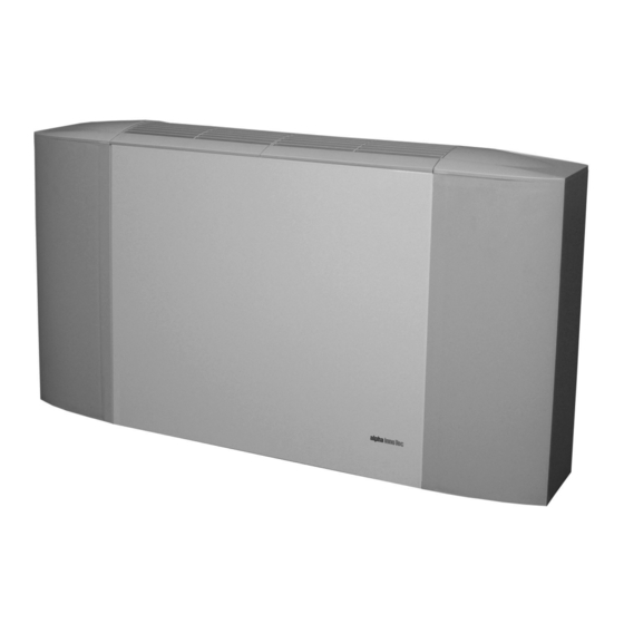
Scope of delivery General • Fan coil THE FAN COIL The GK (fan coil) has been designed for space air condi- Accessories tioning and can be used for heating and cooling. A fan passes the air over the heat exchanger, through which hot or cold water flows. -
Page 6: Care Of The Unit
Care of the unit THE INTERNAL STRUCTURE The inside of the unit consists of a zinc plated metal You can clean the outer surfaces of the unit with a damp sheet of 0.8 and 1 mm thick. On the back of the GK(R) cloth and proprietary household cleaning products. - Page 7 THE FILTER THE COVERS The intake air filter, made of nylon (filter class G1), is fixed The covers are made of painted sheet metal or ABS plas- to the underside of the unit by a slide-in metal frame. tic. They are fixed to the inside of the unit with screws On the one hand this prevents dirt from getting into the (standard colour, RAL 9010).
- Page 8 FAN UNIT THE CONTROL BOX The fan unit, consisting of a radial fan, electric motor Control (1) and terminal box (2) contain the TOP-2 con- and a voltage transformer, is mounted on a baseplate, troller integrated in the side panelling. with insulation to prevent structure-borne sound.
-
Page 9: Installation
Installation TO BE NOTED BEFORE INSTALLATION All fan coils are delivered packed in a cardboard box. The sticker on the outside of the packaging identifies the model, size, fit of the water connections to the fan coil and all accessory parts contained in the packaging. To avoid damage or contamination of the heat exchang- er, the unit should not be unpacked until immediately before installation. -
Page 10: System Accessories
System accessories NOTE. Always maintain a minimum distance from the wall at the side of 200 mm. ADJUSTABLE FEET FOR FLOOR INSTALLATION (GKF) IMPORTANT The accessories consist of 4 parts: two support brackets To ensure a correct air intake, the minimum and two plastic elements, which extend the side profiles distance from the floor must be ≥... -
Page 11: Condensate Pump (Gkp)
CONDENSATE PUMP (GKP) IMPORTANT Immersion or installation in wet rooms is not The pump is used to dispose of condensate if the waste- allowed. water pipe is located higher. The condensate pump is equipped with an alarm function and switches off the GK(R) if the quantity of condensate produced is greater IMPORTANT than the quantity that can be removed. - Page 12 ndensa al fi ianco come indicato ne elle foto 5a, ith the scre ews and spa acers as in ndicated in Align the condensate pump vertically and screw on Use a hose (6 mm ø inside) to connect the discharge the left side of the mounting rail…...
-
Page 13: Connections
Connections INSULATING THE HYDRAULIC CONNECTIONS Insulate all connections vapour diffusion-tight in accordance with the relevant local standards and WATER CONNECTION guidelines. To achieve maximum heat exchanger efficiency, always note and follow the manufacturer's data on the side of the fan coil (flow / return on the heat exchanger). Mixing up the water connections would not impair op- eration, but reduces the heat exchanger efficiency. -
Page 14: Electrical Connection
Electrical connection WIRING THE MOTOR The circuit diagrams apply to all fan coil sizes. DANGER! Risk fatal electric shock! Electri- cal connection work is to be carried out by qualified electricians only. Before opening the unit, disconnect the sys- tem from the power supply and prevent it from being switched back on! The motor of the GKR 5 - 20 units is a single phase motor with only one rotational speed. -
Page 15: Operating Several Units
Operating several units (MASTER/SLAVE PRINCIPLE) ELMZ The ELMZ is a unit for connecting several fan coils by ap- plying the master/slave principle. The device consists of TOP2 three relays, one for each operating speed. The termi- ELMZ nal strips and the relays are mounted on a circuit board. ELMZ The max. -
Page 16: Commissioning
Commissioning OUTLET GRILLE AND FIXING THE COVERS The grilles are latched into place on the unit. They only Check the following before switching on the fan coil: have to be lifted up to remove them. The unit must be connected to the building's earth- The fan coils are delivered with forward-facing venti- ing system and appropriate electrical protection el- lation slots made in the factory.. -
Page 17: Maintenance
Maintenance Undo the screws in the heat exchanger and remove the heat exchanger… Break through the penetrations provided on the REMOVING AND CLEANING THE FILTER side, rotate the coil through 180°, feed the connec- tions through the exposed recesses and re-tighten To ensure proper efficiency of the fan coil it is necessary the heat exchanger screws…... -
Page 18: Replacing The Motor
REPLACING THE MOTOR CLEANING THE CONDENSATE TRAYS CAUTION. The condensate trays should be checked for dirt at least once a year (bacteria, germs and mould growth) and if necessary cleaned. Dismantling DANGER! Risk of fatal electric shock! MOTOR WITH ONE FAN IMPELLER (GK... 6, GK... 11): Electrical connections may be installed only Proceed as follows: by qualified electricians. -
Page 19: Technical Data
Technical data Supply 230 V – 50 Hz AC - output Control range 5 - 30 °C Adjustable neutral range 1 - 5 °C Temperature sensor NTC 10k - 25°C -1% Operating temperature limits (flow temperature) 5 - 50 °C 10 - 90% RH Operating humidity limits (in non-saturated room) -
Page 20: Cooling Output At The Three Standard Speeds
COOLING OUTPUT AT THE THREE STANDARD WATER VOLUME OF THE HEAT EXCHANGER SPEEDS Size GK... 6 GK... 11 GK... 21 The following table shows the cooling output, flow rate Volume for one row 1 0.171 0.256 0.397 and the corresponding pressure loss of the fan coil at: Heat exchanger rows Room temperature 26°C - cooling water 16 - 22°C MAX MED MIN... -
Page 21: Models And Sizes
Models and sizes DIMENSIONS AND WEIGHT Weight [kg] Model without housing with housing GK... 6 GK... 11 GK... 21 Dimensions [mm] Model GK... 6 GK... 11 GK... 21 1120 1006 A1 = connection for condensate drain Heat exchanger connections Connections ½” internal thread 83018200bEN –... - Page 22 Terminal diagram Stand alone 230V 50 Hz SUMMER / WINTER SENSOR (to be installed in the main coil by the factory) ROOM TEMPERATURE SENSOR (to be installed on the inlet by the factory) We reserve the right to modify technical specifications without prior notice.
- Page 23 Terminal diagram Master 230V 50 Hz SUMMER / WINTER SENSOR (to be installed in the main coil by the factory) 83018200bEN – Translation of the operating manual © ait-deutschland GmbH We reserve the right to modify technical specifications without prior notice.
- Page 24 Terminal diagram Slave TO MASTER O PREVIOUS SLAVE We reserve the right to modify technical specifications without prior notice.
-
Page 25: Controller Description
Controller description TOP-2 OPERATION: TOP-2 is an electronic room temperature controller for Operation using the buttons arranged around the dis- fan coils complete with automatic or manual selection of play: the three fan levels or the heating and cooling function. Button Desig- Main function Secondary... - Page 26 BUTTON NOTE. (MENU) If the fan operates with release temperatures (P18 / P19) it is not started until the lamellar heat Press this button to open the sub-menus for settings exchanger temperature has reached the set – FAN flashes on the display. Press the + or – button to parameters.
- Page 27 WEEKLY TIMER PROGRAM TABLE 1: EXAMPLE OF PROGRAM SETTINGS (1 DAY): Press the Menu button, use the + button to scroll and Period F1: 09:00 to 20:00 with set temperature 20°C use the Menu button to select PROG. Period F2: 20:00 to 09:00 with set temperature 15°C Select the day to be programmed by scrolling with the Set temperature value...
- Page 28 TABLE 2: TABLE 3: EXAMPLE OF A WEEKLY TIME PROGRAM EXAMPLE OF PROGRAM SETTINGS (1 WEEK): Time Set value Time Set value 08:00 20°C 23:00 15°C 14:00 20°C 23:00 15°C 14:00 20°C 23:00 15°C 14:00 15°C 23:00 15°C 14:00 20°C 23:00 15°C 14:00...
- Page 29 TABLE 4: ALARM PARAMETER SETTINGS MENU Display Alarm description Reset alarm NOTE. message Changing parameters to values different from ALL FIL : Open the alarm the recommended factory setting can result in and press the Operating hours malfunctions and faults. Menu button (P22) exceeded...
- Page 30 TABLE 5: FIRST PARAMETER LEVEL Para- Function Factory setting Possible settings meter TIMER PROGRAM 0 = off 0 = off 1 = on PtaB DEFAULT PARAMETER SETTINGS This parameter may not be changed. NEUTRAL ZONE 1.0K 0….10K (e.g. room temperature set value 20°C >...
- Page 31 TABLE 6: SECOND PARAMETER LEVEL Para- Function Default Possible settings meter settings PROPORTIONAL BAND 1.0….5.0K Controls the fan speed. E.g. setting 3K Set temperature 20°C Fan level 1: 1K deviation Fan level 2: 2K deviation Fan level 3: 3K deviation NOT RELEVANT This parameter may not be changed.
- Page 32 Para- Function Default Possible settings meter settings 1 = °F NOT RELEVANT This parameter may not be changed. LCD BACKGROUND 0 = off 0….5 LIGHTING MINIMUM LIGHT IN STANDBY MODE MODBUS NETWORK ADDRESS 0….255 (0 = broadcast) NOT RELEVANT This parameter may not be changed. VALVE OPEN TIME 5 minutes 1….100 minutes...
- Page 33 83018200bEN – Translation of the operating manual © ait-deutschland GmbH We reserve the right to modify technical specifications without prior notice.
-
Page 34: Declaration Of Conformity
This declaration becomes invalid if any changes are made to the unit(s) without prior consultation with us and our prior consent. DESIGNATION OF THE UNIT(S) Unit type Order number Unit type Order number GKA 6 15076001 GKS 6 15076601 GKA 11 15076101 GKS 11... - Page 35 83018200bEN – Translation of the operating manual © Alpha-InnoTec GmbH We reserve the right to modify technical specifications without prior notice.
- Page 36 Industriestrasse 3 D-95359 Kasendorf e-Mail: info@alpha-innotec.com www.alpha-innotec.com...
Need help?
Do you have a question about the GKA 6 and is the answer not in the manual?
Questions and answers