Advertisement
Quick Links
1-1
Overview
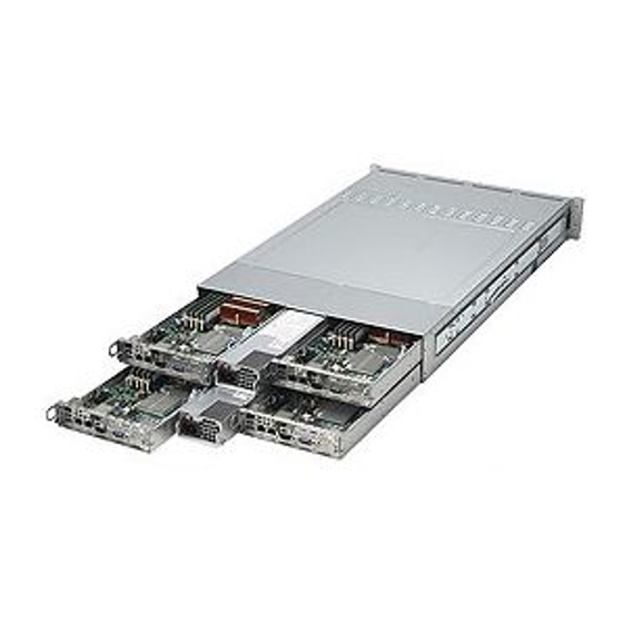
The A+ Server 2021TM-BTRF/BIBXRF is a high-end server comprised of two main
subsystems: the SC827 2U server chassis and the H8DMT-F/H8DMT-IBXF dual
processor serverboard. Please refer to our web site for information on operating
systems that have been certifi ed for use with the system (www.supermicro.com).
In addition to the serverboard and chassis, various hardware components have
been included with the 2021TM-BTRF/BIBXRF, as listed below:
•
Eight passive CPU heatsinks (SNK-P0022+)
•
Four 8-cm chassis fans (FAN-0111L4)
•
Four air shrouds (MCP-310-82703-0B)
•
Four riser cards (RSC-R1U-E16R-O-P)
•
SATA Accessories
One SATA backplane (BPN-SAS-827B)
Four 16-pin to 16-pin front control cable (CBL-0151L)
Four sets of SATA cables (CBL-0317L)
Four 4-pin fan cables (CBL-0320L)
Four 4-pin to 4-pin I2C cables (CBL-0323L)
Twelve 3.5" hot-swappable drive carriers (MCP-220-00024-0B)
•
One rackmount kit (MCP-290-00053-0N)
•
One CD containing manual, drivers and utilities
Chapter 1
Introduction
1-1
Chapter 1: Introduction
Advertisement

Related Manuals for Supermicro A+ 2021TM-BTRF


Summary of Contents for Supermicro A+ 2021TM-BTRF
- Page 1 SC827 2U server chassis and the H8DMT-F/H8DMT-IBXF dual processor serverboard. Please refer to our web site for information on operating systems that have been certifi ed for use with the system (www.supermicro.com). In addition to the serverboard and chassis, various hardware components have been included with the 2021TM-BTRF/BIBXRF, as listed below: •...
- Page 2 The H8DMT-F/H8DMT-IBXF supports single or dual AMD Opteron 2000 series processors (Socket F type). Please refer to the serverboard description pages on our web site for a complete listing of supported processors (www.supermicro.com). Memory The H8DMT-F/H8DMT-IBXF has eight 240-pin DIMM slots that can support up to 64 GB of DDR2-800/667/533 registered ECC SDRAM.
- Page 3 Chapter 1: Introduction Onboard Controllers/Ports One Fast UART 16550 compatible serial port and a Mellanox Connect-X MT25408 20Gb/s Infi niBand controller are located on the serverboard. The color-coded I/O ports include one COM port (an additional COM header is located on the serverboard), a VGA (monitor) port, two USB 2.0 ports (additional 2+2 internal USB headers are included on the serverboard) and two gigabit Ethernet ports.
- Page 4 A+ SERVER 2021TM-BTRF/BIBXRF User's Manual Front Control Panel SC827 models include four front panels on the handles of the chassis which control each of the systems. Each control panel on the A+ Server 2021TM-BTRF/BIBXRF provides you with system monitoring and control for one server node. LEDs indicate system power, HDD activity, network activity, system overheat and power supply failure.
- Page 5 Chapter 1: Introduction Figure 1-1. nVidia MCP55 Pro Chipset: System Block Diagram Note: This is a general block diagram. Please see Chapter 5 for details. Socket F Socket F 6x USB PCI x16 MCP55 PRO S PCI x8 4x SATA SATA 4x Fan W83793AG...
- Page 6 Super Micro Computer, Inc. 980 Rock Ave. San Jose, CA 95131 U.S.A. Tel: +1 (408) 503-8000 Fax: +1 (408) 503-8008 Email: marketing@supermicro.com (General Information) support@supermicro.com (Technical Support) Web Site: www.supermicro.com Europe Address: Super Micro Computer B.V. Het Sterrenbeeld 28, 5215 ML...
- Page 7 Chapter 1: Introduction 2U Twin : System Notes As a 2U Twin confi guration, the 2021TM-BTRF/BIBXRF is a unique server system. With four system boards incorporated into a single chassis acting as four separate nodes, there are several points you should keep in mind. Nodes Each of the four serverboards act as a separate node in the system.
- Page 8 A+ SERVER 2021TM-BTRF/BIBXRF User's Manual Notes...
- Page 9 Chapter 2: Server Installation Chapter 2 Server Installation Overview This chapter provides a quick setup checklist to get your A+ Server 2021TM-BTRF/ BIBXRF up and running. Following these steps in the order given should enable you to have the system operational within a minimum amount of time. This quick setup assumes that your system has come to you with the processors and memory preinstalled.
- Page 10 A+ SERVER 2021TM-BTRF/BIBXRF User's Manual • This product is for installation only in a Restricted Access Location (dedicated equipment rooms, service closets and the like). • This product is not suitable for use with visual display work place devices acccording to §2 of the the German Ordinance for Work with Visual Display Units.
- Page 11 Chapter 2: Server Installation Rack Mounting Considerations Ambient Operating Temperature If installed in a closed or multi-unit rack assembly, the ambient operating temperature of the rack environment may be greater than the ambient temperature of the room. Therefore, consideration should be given to installing the equipment in an environment compatible with the manufacturer’s maximum rated ambient temperature (Tmra).
- Page 12 A+ SERVER 2021TM-BTRF/BIBXRF User's Manual Installing the System into a Rack This section provides information on installing the SC827 chassis into a rack unit with the quick-release rails provided. There are a variety of rack units on the market, which may mean the assembly procedure will differ slightly.
- Page 13 Chapter 2: Server Installation Figure 2-2: Installing the Inner Rail Extensions Installing the Inner Rail Extension The SC827 chassis includes a set of inner rails in two sections: inner rails and inner rail extensions. The inner rails are pre-attached to the chassis, and do not interfere with normal use of the chassis if you decide not to use a server rack.
- Page 14 A+ SERVER 2021TM-BTRF/BIBXRF User's Manual Figure 2-3. Assembling the Outer Rails Outer Rack Rails Outer rails attach to the rack and hold the chassis in place. The outer rails for the SC827 chassis extend between 30 inches and 33 inches. Installing the Outer Rails to the Rack Secure the back end of the outer rail to the rack, using the screws provided.
- Page 15 Chapter 2: Server Installation Figure 2-4: Installing the Rack Rails Installing the Chassis into a Rack Extend the outer rails as illustrated above. Align the inner rails of the chassis with the outer rails on the rack. Slide the inner rails into the outer rails, keeping the pressure even on both sides.
- Page 16 A+ SERVER 2021TM-BTRF/BIBXRF User's Manual Checking the Serverboard Setup After you install the 2021TM-BTRF/BIBXRF in the rack, you will need to open the unit to make sure the serverboard is properly installed and all the connections have been made. Accessing the inside of the System Before operating the server for the fi...
- Page 17 Chapter 2: Server Installation Figure 2-5. Accessing the Inside of the System Remove two screws Check Ventilation Openings...
- Page 18 A+ SERVER 2021TM-BTRF/BIBXRF User's Manual Checking the Drive Bay Setup Next, you should check to make sure the peripheral drives and the SATA drives have been properly installed and all connections have been made. Checking the Drives All drives are accessable from the front of the server. For servicing the DVD- ROM and fl...
- Page 19 Chapter 3: System Interface Chapter 3 System Interface Overview There are several LEDs on the control panel and on the drive carriers to keep you constantly informed of the overall status of the system. SC827 models include four front panels on the handles of the chassis which control each of the systems. This chapter explains the meanings of all LED indicators and the appropriate re- sponse you may need to take.
- Page 20 A+ SERVER 2021TM-BTRF/BIBXRF User's Manual Control Panel Button • Power: The main power button on each of the four control panels is used to apply or remove power from the power supply to each of the four systems in the chassis. Turning off system power with this button removes the main power, but keeps standby power supplied to the system.
- Page 21 Chapter 3: System Interface Drive Carrier LEDs The server chassis uses SATA drives. SATA Drives Each SATA drive carrier has two LEDs. • Green: Each Serial ATA drive carrier has a green LED. When illuminated, this green LED (on the front of the SATA drive carrier) indicates drive activity. A con- nection to the SATA backplane enables this LED to blink on and off when that particular drive is being accessed.
- Page 22 A+ SERVER 2021TM-BTRF/BIBXRF User's Manual Notes...
- Page 23 Chapter 4: System Safety Chapter 4 System Safety Electrical Safety Precautions Basic electrical safety precautions should be followed to protect yourself from harm and the A+ SERVER 202ITM-BTRF/BIBXRF from damage: • Be aware of the locations of the power on/off switch on the chassis as well as the room's emergency power-off switch, disconnection switch or electrical outlet.
- Page 24 A+ SERVER 2021TM-BTRF/BIBXRF User's Manual • The power supply power cords must include a grounding plug and must be plugged into grounded electrical outlets. • This product may be connected to an IT power system. In all cases, make sure that the unit is also reliably connected to Earth (ground).
- Page 25 Chapter 4: System Safety • While working on the system, do not wear loose clothing such as neckties and unbuttoned shirt sleeves, which can come into contact with electrical circuits or be pulled into a cooling fan. • Remove any jewelry or metal objects from your body, which are excellent metal conductors that can create short circuits and harm you if they come into contact with printed circuit boards or areas where power is present.
- Page 26 A+ SERVER 2021TM-BTRF/BIBXRF User's Manual • For grounding purposes, make sure your computer chassis provides excellent conductivity between the power supply, the case, the mounting fasteners and the serverboard. Operating Precautions Care must be taken to assure that the chassis cover is in place when the 202ITM-BTRF/BIBXRF is operating to assure proper cooling.
- Page 27 Chapter 5: Advanced Serverboard Setup Chapter 5 Advanced Serverboard Setup This chapter covers the steps required to install the H8DMT-F/H8DMT-IBXF serverboard into the chassis, connect the data and power cables and install add-on cards. All serverboard jumpers and connections are also described. A layout and quick reference chart are included in this chapter for your reference.
- Page 28 The H8DMT-F/H8DMT-IBXF requires a chassis big enough to support a 16.4" x 6.5" serverboard, such as Supermicro's SC827B-R1200B. Make sure that the I/O ports on the serverboard align properly with their respective holes in the I/O shield at the back of the chassis.
- Page 29 Chapter 5: Advanced Serverboard Setup Connecting Cables Now that the serverboard is installed, the next step is to connect the cables to the board. These include the data cables for the peripherals and control panel and the power cables. Connecting Data Cables The cables used to transfer data from the peripheral devices have been carefully routed to prevent them from blocking the fl...
- Page 30 A+ SERVER 2021TM-BTRF/BIBXRF User's Manual Figure 5-1. Control Panel Header Pins Ground x (Key) x (Key) Power On LED HDD LED NIC1 LED NIC2 LED OH/Fan Fail LED Power Fail LED Ground Reset (Button) Ground Power (Button) I/O Ports The I/O ports are color coded in conformance with the PC 99 specifi cation. See Figure 5-2 below for the colors and locations of the various I/O ports.
- Page 31 CPU cap is in place and none of the socket pins are bent; otherwise, contact your retailer immediately. Refer to the Supermicro web site for updates on CPU support. Installing an Opteron 2000 Processor Note: The photos on this page and succeeding pages are for illustration purposes only.
- Page 32 A+ SERVER 2021TM-BTRF/BIBXRF User's Manual Once aligned, carefully place the CPU into the socket. Do not drop the CPU on the socket, move the CPU horizontally or vertically or rub the CPU against the socket or against any pins of the socket, which may damage the CPU and/ or the socket.
- Page 33 See Figure 2-1. Repeat for the second CPU socket. Note: BKT-0012L is included for use with non-Supermicro heatsinks only. When installing Supermicro heatsinks, only BKT-0011L (the pre-installed CPU backplate) is needed. The BKT-0012L retention module was designed to provide compatibility with clip-and-cam type heatsinks from third parties.
- Page 34 A+ SERVER 2021TM-BTRF/BIBXRF User's Manual Removing the Heatsink Warning: We do not recommend removing the CPU or the heatsink. If you do need to remove the heatsink, please follow the instructions below to prevent damage to the CPU or other components. Removing a Passive Heatsink Unplug the power cord from the power supply.
- Page 35 Chapter 5: Advanced Serverboard Setup Figure 5-3. DIMM Installation DDR2 To Install: Insert module verti- cally and press down until it snaps into place. Pay attention to the bottom notches. To Remove: Use your thumbs to gently push each release tab outward to free the DIMM from the slot.
- Page 36 A+ SERVER 2021TM-BTRF/BIBXRF User's Manual Memory Population for Optimal Performance (For Interleaved 128-bit Operation) # DIMMs CPU1 Branch0 CPU1 Branch1 CPU2 Branch0 CPU Branch1 DIMM1A DIMM1B 2 DIMMs DIMM2A DIMM2B DIMM1A DIMM1B DIMM1A DIMM1B DIMM1A DIMM1B DIMM2A DIMM2B DIMM1A DIMM1B DIMM2A DIMM2B 4 DIMMs...
- Page 37 Chapter 5: Advanced Serverboard Setup Possible System Memory Allocation & Availability System Device Size Physical Memory Remaining (-Available) (4 GB Total System Memory) Firmware Hub fl ash memory (System BIOS) 1 MB 3.99 GB Local APIC 4 KB 3.99 GB Area Reserved for the chipset 2 MB 3.99 GB...
- Page 38 A+ SERVER 2021TM-BTRF/BIBXRF User's Manual Serverboard Details Figure 5-4. H8DMT-F/H8DMT-IBXF Layout (not drawn to scale) COM1 VGA1 InfiniBand JIB1 LAN2 LAN1 USB1/2 InfiniBand Windbond Controller WPCM450 BMC Video JBMC1 BIOS CMOS CLEAR MCP55 Pro JI2C1 JI2C2 SPEAKER T-SGPIO1 JWOL CPU1 USB 2/3 JSMB1 BATTERY...
- Page 39 Chapter 5: Advanced Serverboard Setup H8DMT-F/H8DMT-IBXF Quick Reference Jumper Description Default Setting JBT1 CMOS Clear See Section 5-9 JBMC1 BMC and Video Enable Header Pins 1-2 (Enabled) JI2C1/JI2C2 I2C to PCI/PCI-E Slots Both Closed (Enabled) JPL1 LAN Controller Enable/Disable Pins 1-2 (Enabled) Watch Dog Pins 1-2 (Reset) JIB1...
- Page 40 A+ SERVER 2021TM-BTRF/BIBXRF User's Manual Connector Defi nitions ATX Power 20-pin Connector Pin Defi nitions (JPW1/JPW2) Pin # Defi nition Pin # Defi nition Main ATX Power Supply Connector PS_ON_N The proprietary power supply connector 5V_STBY (JWR1 and JWR2) meets the SSI (Superset ATX) 20-pin specifi...
- Page 41 Chapter 5: Advanced Serverboard Setup Overheat/Fan Fail LED (OH) OH/Fan Fail LED Pin Defi nitions (JF1) Connect an LED to the OH connection on Pin# Defi nition pins 7 and 8 of JF1 to provide advanced warning of chassis overheating. Refer to the Ground table on the right for pin defi...
- Page 42 A+ SERVER 2021TM-BTRF/BIBXRF User's Manual NMI Button NMI Button Pin Defi nitions (JF1) The non-maskable interrupt button header is Pin# Defi nition located on pins 19 and 20 of JF1. Refer to the Control table on the right for pin defi nitions. Ground Universal Serial Bus (USB) Back Panel USB...
- Page 43 Chapter 5: Advanced Serverboard Setup Fan Headers Fan Header Pin Defi nitions The H8DMT has four 4-pin proprietary fan (FAN1-4) headers. Each fan header supports one Pin# Defi nition 4-pin fans with PWM mode. See the table Ground (Black) to the right for pin defi nitions. Pins 1-3 of the +12V (Red) fan headers are backward compatible with Tachometer...
- Page 44 A+ SERVER 2021TM-BTRF/BIBXRF User's Manual Wake-On-LAN Wake-On-LAN Pin Defi nitions The Wake-On-LAN header is designated (JWOL) JWOL on the serverboard. See the table Pin# Defi nition on the right for pin defi nitions. You must +5V Standby also have a LAN card with a Wake-On-LAN Ground connector and cable to use this feature.
- Page 45 Chapter 5: Advanced Serverboard Setup 5-10 Jumper Settings Explanation of Jumpers To modify the operation of the serverboard, jumpers can be used Connector to choose between optional settings. Pins Jumpers create shorts between two pins to change the function of the connector.
- Page 46 A+ SERVER 2021TM-BTRF/BIBXRF User's Manual LAN1/2 Enable/Disable JLAN1/2 Enable/Disable Jumper Settings (JPL) Change the setting of jumper JPL to enable Jumper Setting Defi nition or disable the LAN Ethernet ports on the Pins 1-2 Enabled serverboard. See the table on the right (Default) for jumper settings.
- Page 47 Chapter 5: Advanced Serverboard Setup Infi niBand Port Enable/Disable Infi niBand Port Enable/ Disable JIB1 enables or disables the Infi niBand port Jumper Settings (JIB1) on the H8DMT/H8DMT-IBX Serverboards. Jumper Setting Defi nition The default position is on pins 1 and 2 to Pins 1-2 Enabled (Default) enable the port.
- Page 48 A+ SERVER 2021TM-BTRF/BIBXRF User's Manual Infi niBand LED Indicators Infi niBand LED Indicators (LE2/LE3) Two Infi niBand LED indicators (LE2/LE3) LED Color Defi nition are located near the Infi niBand port of the Green: No Connection H8DMT/H8DMT-IBX Serverboards. The green LED (LE2) is the Infi niBand link LED Green: Infi...
- Page 49 5-13 Installing Software After the hardware has been installed, you should fi rst install the operating system and then the drivers. The necessary drivers are all included on the Supermicro CDs that came packaged with your motherboard. Figure 5-5. Driver/Tool Installation Display Screen Note: Click the icons showing a hand writing on paper to view the readme fi...
- Page 50 A+ SERVER 2021TM-BTRF/BIBXRF User's Manual Supero Doctor III The Supero Doctor III program is a Web based management tool that supports remote management capability. It includes Remote and Local Management tools. The local management is called SD III Client. The Supero Doctor III program included on the CD-ROM that came with your motherboard allows you to monitor the environment and operations of your system.
- Page 51 Figure 5-7. Supero Doctor III Interface Display Screen (Remote Control) Note: SD III Software Revision 1.0 can be downloaded from our Web Site at: ftp://ftp. supermicro.com/utility/Supero_Doctor_III/. You can also download the SDIII User's Guide at: <http://www.supermicro.com/PRODUCT/Manuals/SDIII/UserGuide.pdf>. For Linux, we will recommend using Supero Doctor II.
- Page 52 A+ SERVER 2021TM-BTRF/BIBXRF User's Manual Notes 5-26...
- Page 53 Chapter 6: Advanced Chassis Setup Chapter 6 Advanced Chassis Setup This chapter covers the steps required to install components and perform maintenance on the SC827-R1200B chassis. For component installation, follow the steps in the order given to eliminate the most common problems encountered. If some steps are unnecessary, skip ahead to the step that follows.
- Page 54 A+ SERVER 2021TM-BTRF/BIBXRF User's Manual Unpacking The serverboard is shipped in antistatic packaging to avoid static damage. When unpacking the board, make sure the person handling it is static protected. Figure 6-1. Front and Rear Chassis Views Control Panel Control Panel Control Panel Control Panel SATA Drives (12)
- Page 55 Chapter 6: Advanced Chassis Setup Chassis Cover Figure 6-2: Removing the Chassis Cover Remove two screws Check Ventilation Openings Before operating the SC827 chassis for the fi rst time, it is important to remove the protective fi lm covering the top of the chassis, in order to allow for proper ventilation and cooling.
- Page 56 A+ SERVER 2021TM-BTRF/BIBXRF User's Manual Air Guides The air guides concentrate and maximize air fl ow in the chassis. These air guides do not require screws to set up, but rather attaches to the serverboard by two tabs on the air guides. The SC827 chassis requires four identical air guides, one in each motherboard drawer.
- Page 57 Chapter 6: Advanced Chassis Setup System Fans Four fans provide cooling for the chassis. These fans circulate air through the chassis as a means of lowering the chassis internal temperature. The SC827 system fans are hot-swappable. There is no need to power down the system when replacing fans and new tools are required for installation.
- Page 58 A+ SERVER 2021TM-BTRF/BIBXRF User's Manual Fan Confi gurations Options SC827B Hot-Swappable Default Confi guration Fan A connected to bplane, bplane connected to Node A by adapter card Fan B connected to bplane, bplane connected to Node B by adapter card Fan C connected to bplane, bplane connected to Node C by adapter card Fan D connected to bplane, bplane connected to Node D by adapter card Changing a System Fan...
- Page 59 Chapter 6: Advanced Chassis Setup Removing and Installing the Backplane The SC827 chassis backplane is located behind the hard drives and in front of the front system fans. In order to change jumper settings on the backplane, it may be necessary to remove the backplane from the chassis.
- Page 60 A+ SERVER 2021TM-BTRF/BIBXRF User's Manual Loosen the three screws in the spring bar, located on the fl oor of the chassis, indicated by the arrows below. Figure 6-7: Loosening the Spring Bar Screws in the Floor of the Chassis Remove the side screw from the side of the chassis. Figure 6-8: Removing the Backplane from the Chassis Gently ease the backplane up and out of the chassis.
- Page 61 Chapter 6: Advanced Chassis Setup Installing the Backplane Installing the Backplane into the Chassis Ensure that all of the hard drive trays have been removed from the bays in the front of the chassis and that the spring bar has been loosened as directed in the previous section.
- Page 62 A+ SERVER 2021TM-BTRF/BIBXRF User's Manual Installing the Motherboard Figure 6-10: I/O Shield Placement I/O Shields I/O Shield The I/O shield holds the motherboard ports in place. The I/O shield does not require installation. Permanent and Optional Standoffs Standoffs prevent short circuits by securing space between the motherboard and the chassis surface.
- Page 63 Chapter 6: Advanced Chassis Setup Figure 6-11: Installing the Motherboard in the Motherboard Node Drawer Installing the Motherboard Review the documentation that came with your motherboard. Become familiar with component placement, requirements, precautions, and cable connections. Pull the motherboard drawer out of the back of the chassis. Remove the add-on card brackets: 3a.
- Page 64 A+ SERVER 2021TM-BTRF/BIBXRF User's Manual Connect the cables between the motherboard, backplane, chassis, front panel, and power supply, as needed. Also, fans may be temporarily removed to allow access to the backplane ports. Replace the add-on card bracket and secure the bracket with a screw. Adapter Card Replacement Each motherboard drawer comes equipped with an adapter card which plugs into the backplane.
- Page 65 Chapter 6: Advanced Chassis Setup Installing the Adapter Card Place the adapter card and spacer plate in the motherboard drawer, aligning the holes in the spacer and the adapter card with the holes in the motherboard drawer. Secure the adapter card and spacer plate to the motherboard drawer, using the fi...
- Page 66 A+ SERVER 2021TM-BTRF/BIBXRF User's Manual Installing Add-on Cards Disconnect the power supply, lay the chassis on a fl at surface, and open the chassis cover. Pull open the add-on card slot clip in the rear of the chassis. Slide the temporary PCI slot shield toward the slot clip and remove the temporary shield from the chassis.
- Page 67 SATA drives. Proceed to the next step for instructions. You must use standard 1" high, SATA drives in the system. Note: Refer to the following FTP site for setup guidelines: <ftp://ftp.supermicro. com/driver/SAS/LSI/LSI_SAS_EmbMRAID_SWUG.pdf> and Supermicro's web site for additional inmformation < http://www.supermicro.com/support/manuals/>.
- Page 68 A+ SERVER 2021TM-BTRF/BIBXRF User's Manual Figure 6-16: Removing Hard Drive Removing Hard Drive Trays from the Chassis Press the release button on the drive tray. This extends the drive bay handle. Use the handle to pull the drive out of the chassis. 6-16...
- Page 69 Chapter 6: Advanced Chassis Setup Figure 6-17: Chassis Drive Tray Dummy Drive Drive Tray The drives are mounted in drive carriers to simplify their installation and removal from the chassis. These carriers also help promote proper airfl ow for the drive bays.
- Page 70 Use the open handle to replace the drive tray into the chassis. Make sure the close the drive tray handle. Warning! Enterprise level hard disk drives are recommended for use in Supermicro chassis and servers. For information on recommended HDDs, visit the Supermicro Web site at http://www.supermicro.com/products/nfo/ storage.cfm.
- Page 71 Replacement units can be ordered directly from Supermicro (See the contact information in the Preface of this manual). Changing the Power Supply Power down all four nodes and unplug the power cord.
- Page 72 A+ SERVER 2021TM-BTRF/BIBXRF User's Manual Figure 6-20: Changing the Power Supply Release Tab 6-20...
- Page 73 When an option is selected in the left frame, it is highlighted in white. Often a text message will accompany it. (Note: the AMI BIOS has default text messages built in. Supermicro retains the option to include, omit, or change any of these text messages.) The AMI BIOS Setup Utility uses a key-based navigation system called "hot keys".
- Page 74 Warning! Do not upgrade the BIOS unless your system has a BIOS-related issue. Flashing the wrong BIOS can cause irreparable damage to the system. In no event shall Supermicro be liable for direct, indirect, special, incidental, or consequential damages arising from a BIOS update. If you have to update the BIOS, do not shut down or reset the system while the BIOS is updating.
- Page 75 Chapter 7: BIOS • Physical Count: This item displays the number of processors installed in your system as detected by the BIOS. • Logical Count: This item displays the number of CPU Cores installed in your system as detected by the BIOS. •...
- Page 76 A+ SERVER 2021TM-BTRF/BIBXRF User's Manual Advanced Setup Confi gurations Use the arrow keys to select Boot Setup and hit <Enter> to access the submenu items: BIOS Features Quick Boot If Enabled, this option will skip certain tests during POST to reduce the time needed for system boot.
- Page 77 Chapter 7: BIOS Advanced ACPI Confi guration Options MCP55 ACPI HPET Table Determines whether to enable or disable the MCP55 ACPI HPET table. Op- tions are Enabled or Disabled. ACPI Version Features Use this setting the determine which ACPI version to use. Options are ACPI v1.0, ACPI v2.0 and ACPI v3.0.
- Page 78 A+ SERVER 2021TM-BTRF/BIBXRF User's Manual Restore on AC Power Loss This setting allows you to choose how the system will react when power returns after an unexpected loss of power. The options are Power Off, Power On and Last State. MPS Revision This setting allows the user to select the MPS (MultiProcessor Specifi...
- Page 79 Chapter 7: BIOS PIO Mode PIO (Programmable I/O) mode programs timing cycles between the IDE drive and the programmable IDE controller. As the PIO mode increases, the cycle time decreases. The options are Auto, 0, 1, 2, 3, and 4. Select Auto to allow BIOS to auto detect the PIO mode.
- Page 80 A+ SERVER 2021TM-BTRF/BIBXRF User's Manual PCI/PnP Confi guration Slot 1 OPROM Use this setting to enable or disable the OPROM (Option ROM fi rmware) for slot 1. The options are Yes and No. Load Onboard LAN Option ROM Use this setting to Enable or Disable the onboard option ROM. This setting must be enabled to view the Boot Menu settings.
- Page 81 Chapter 7: BIOS Enable Clock to All Dimms Use this setting to enable unused clocks to all DIMMSs, even if some DIMM slots are unpopulated. Options are Enabled and Disabled. Mem Clk Tristate C3/ALTVID Use this setting to Enable or Disable memory clock tristate during C3 and ALT VID.
- Page 82 A+ SERVER 2021TM-BTRF/BIBXRF User's Manual DRAM SCRUB Redirect Allows system to correct DRAM ECC errors immediately, even with back- ground scrubbing on. Options are Enabled and Disabled. 4-Bit ECC Mode Allows the user to enabled 4-bit ECC mode (also known as ECC Chipkill). Options are Enabled and Disabled.
- Page 83 Chapter 7: BIOS SouthBridge/MCP55 Confi guration This feature allows the user to confi gure the settings for the Intel ICH South Bridge chipset. CPU/LDT Spread Spectrum Enables spread spectrum for the CPU/LDT. Options are Center Spread, Down Spread or Disabled. PCIE Spread Spectrum Allows you to Enable or Disable spread spectrum for PCI-Express.
- Page 84 A+ SERVER 2021TM-BTRF/BIBXRF User's Manual Power Now This setting is used to Enable or Disable the AMD Power Now feature. Options are Enabled and Disabled. Secure Virtual Machine Mode This setting is used to Enable or Disable SVM (Secure Virtual Machine). Options are Enabled and Disabled.
- Page 85 Chapter 7: BIOS Serial Port Number Selects the serial port to use for console redirection. Options are COM1 and COM2. Serial Port Mode Selects the serial port settings to use. Options are (115200 8, n, 1), (57600 8, n, 1), (38400 8, n, 1), (19200 8, n, 1) and (09600 8, n, 1). Flow Control Selects the fl...
- Page 86 A+ SERVER 2021TM-BTRF/BIBXRF User's Manual CPU temperature has dropped to 5 degrees below the threshold set. The default setting is 72o C. Warning! 1. Any temperature that exceeds the CPU threshold temperature pre- defi ned by the CPU manufacturer may result in CPU overheat or system instability.
- Page 87 ‘Temperature Tolerance’ is, and not the other way around. This results in better CPU thermal management. Supermicro has leveraged this feature by assigning a temperature status to certain thermal conditions in the processor (Low, Medium and High). This makes it easier for the user to understand the CPU’s temperature status, rather than by just simply seeing a temperature reading (i.e., 25...
- Page 88 A+ SERVER 2021TM-BTRF/BIBXRF User's Manual Voltage Monitoring CPU1 Vcore/CPU2 Vcore, CPU1 DIMM/CPU2 DIMM, 1.5V, 3.3Vcc (V), 3.3V SB (V), 12Vcc (V), 5Vin, and Battery Voltage. IPMI Confi guration Intelligent Platform Management Interface (IPMI) is a set of common interfaces that IT administrators can use to monitor system health and to manage the system as a whole.
- Page 89 Chapter 7: BIOS Set PEF Confi guration PEF Support Use this setting to Enable or Disable PEF support. Options are Enabled and Disabled. When enabled, the following settings will appear: PEF Action Global Control Options are Alert, Power Down, Reset Sysytem, Power Cycle, OEM Action and Diagnostic Int.
- Page 90 A+ SERVER 2021TM-BTRF/BIBXRF User's Manual Hard Disk Drives This feature allows the user to specify the boot sequence from all available hard disk drives. The settings are Disabled and a list of all hard disk drives that have been detected (i.e., 1st Drive, 2nd Drive, 3rd Drive, etc). Security Settings The AMI BIOS provides a Supervisor and a User password.
- Page 91 Chapter 7: BIOS Boot Sector Virus Protection When Enabled, the AMI BIOS displays a warning when any program (or virus) issues a Disk Format command or attempts to write to the boot sector of the hard disk drive. The options are Enabled and Disabled. Exit Options Select the Exit tab from the AMI BIOS Setup Utility screen to enter the Exit BIOS Setup screen.
- Page 92 A+ SERVER 2021TM-BTRF/BIBXRF User's Manual Notes 7-20...
- Page 93 Appendix A: BIOS Error Beep Codes Appendix A BIOS Error Beep Codes During the POST (Power-On Self-Test) routines, which are performed each time the system is powered on, errors may occur. Non-fatal errors are those which, in most cases, allow the system to continue the boot-up process.
- Page 94 A+ SERVER 2021TM-BTRF/BIBXRF User's Manual Notes...
- Page 95 Appendix B: System Specifi cations Appendix B System Specifi cations Note: unless noted specifi cations apply to a complete system (all serverboards). Processors Eight AMD Opteron 2000 series processors (Socket F type) (both CPUs must be of the same type) Note: Please refer to our web site for a complete listing of supported processors.
- Page 96 A+ SERVER 2021TM-BTRF/BIBXRF User's Manual Serverboard Four H8DMT-F/H8DMT-IBXF (Extended ATX form factor) Dimensions: 16.4" x 6.5" (417 x 165 mm) Chassis SC827B-R1200B (2U rackmount) Dimensions: (WxHxD) 17.25 x 3.47 x 28.5 in. (438 x 88 x 724 mm) Weight Gross (Bare Bone): 65 lbs. (29.5 kg.) System Cooling Four 8-cm PWM system cooling fans System Input Requirements...
- Page 97 Appendix B: System Specifi cations Regulatory Compliance Electromagnetic Emissions: FCC Class A, EN 55022 Class A, EN 61000-3-2/-3- 3, CISPR 22 Class A Electromagnetic Immunity: EN 55024/CISPR 24, (EN 61000-4-2, EN 61000-4-3, EN 61000-4-4, EN 61000-4-5, EN 61000-4-6, EN 61000-4-8, EN 61000-4-11) Safety: CSA/EN/IEC/UL 60950-1 Compliant, UL or CSA Listed (USA and Canada), CE Marking (Europe) California Best Management Practices Regulations for Perchlorate Materials:...
- Page 98 A+ SERVER 2021TM-BTRF/BIBXRF User's Manual (continued from front) The products sold by Supermicro are not intended for and will not be used in life support systems, medical equipment, nuclear facilities or systems, aircraft, aircraft devices, aircraft/emergency communication devices or other critical systems whose failure to perform be reasonably expected to result in signifi...
Need help?
Do you have a question about the A+ 2021TM-BTRF and is the answer not in the manual?
Questions and answers