Table of Contents
Advertisement
Quick Links
Advertisement
Table of Contents

Related Manuals for Kernel KN-5000C


Summary of Contents for Kernel KN-5000C
- Page 1 This manual applicable to KN-5000C/ KN-5000D.
- Page 3 If you want to get more accurate information and perfect service, please log in www.kerneluvb.com...
- Page 4 Preface Dear users, first of all, thanks for your trust and using 308nm Excimer System manufactured by our company. Please read this manual and attached documentations carefully before your first installation and using this system. To improve capability and reliability of equipment, we will continuously upgrade our product (including hardware and software).
- Page 5 Version: V1.1...
- Page 6 Important Notice Please carefully read the instructions in the “safety requirements”, “Note” and the special warnings “ “ part of the content. If you have any problem or need help in using, please contact our technical service center for help in time. We will give you technical support or arrange professional technical expert for service at the first time.
- Page 7 safety, reliability or performance of this equipment by not observing the instructions! Any faults arising from such non-observance will invalidate the warranty!
-
Page 8: Table Of Contents
Contents Safety requirements and precautions ........1 1.1 Safety Information ................1 1.2 Precautions ..................3 Overview ..................8 2.1 Product introduction ............... 8 2.2 Structural composition ..............12 2.3 Identifier declaration ..............16 2.4 Characteristic parameters ............17 Installation ..................19 3.1 Unpacking inspection .............. - Page 9 Appendix C Preset output dose of the MED skin test ....79 Appendix D Conversion of irradiation dose/irradiation time . 82 Appendix E Patient log ............... 84 Appendix F Electromagnetic compatibility statement ....86 KN-5000C Packing List ............... 95 KN-5000D Packing List ............... 96...
-
Page 10: Safety Requirements And Precautions
1 Safety requirements and precautions 1.1 Safety Information ⚫ Please note that the following conditions should not be treated with UV radiation: patients with solar dermatitis, lupus erythematosus, malignant tumors, xeroderma pigmentosum, Bloom syndrome and dermatomyositis, pregnant women, and other patients that are not suitable for UV irradiation treatment. - Page 11 fire or explosion. ⚫ In order to prevent circuit hazard, the equipment can only be connected to a power socket that has a protective ground. Do not use the power socket if it is not connected to a ground lead or the integrity of the ground lead is uncertain.
-
Page 12: Precautions
password. Please keep the password safely to avoid password leakage or forgetting. ⚫ Do not modify this equipment without authorization of the manufacturer. ⚫ Use of controls or adjustments or performance of procedures other than those specified herein may result in hazardous radiation exposure ⚫... - Page 13 with an AC regulated power supply with an accuracy of 2%. ⚫ Before using the equipment, inspect the equipment and its connecting cables and accessories carefully to ensure they can work normally and safely. ⚫ Before treatment, the operator should know the MED (minimum erythema dose) test value of the patient.
- Page 14 skin after phototherapy, the dermatologist should be consulted and appropriate measures should be taken. ⚫ The operator should pay attention to the accumulation of the irradiation dose. ⚫ The equipment will produce a small amount of ozone during use. Please keep indoor ventilation when using it. If you are sensitive to ozone smell, it is recommended to wear a mask.
- Page 15 ⚫ In order to ensure the safe operation of the equipment, please use the replaceable parts, accessories and various consumables supplied or specified by Kernel for the equipment. ⚫ Accessories and equipment disposal When handling the packaging materials, the relevant local regulations or the waste disposal system of the hospital shall be observed strictly.
- Page 16 instruction for use must be followed. However, the accepted medical practice experience with patient care must not be replaced by the instruction for use. Keep this manual near the equipment so that it is available and can be easily accessed when needed.
-
Page 17: Overview
2 Overview 2.1 Product introduction ⚫ Ultraviolet (UV) phototherapy originated in the 1920s and the technology of artificial light source has developed rapidly due to the development of science and technology. Among them, UVB therapy, as a representative, has become one of the effective methods for treating various skin diseases in developed countries, such as Europe and America. - Page 18 2.1.1 Indication for use This system is indicated for the treatment of psoriasis and vitiligo. Patient group: Adults 2.1.2 Contraindications Please note that the following conditions should not be treated with UV radiation: patients with solar dermatitis, lupus erythematosus, malignant tumors, xeroderma pigmentosum, Bloom syndrome and dermatomyositis, pregnant women, and other patients that are not suitable for UV irradiation treatment.
- Page 19 Warning! ⚫ The equipment should only be used by or under the direction of professional clinicians. Professional clinicians using equipment should be trained and qualified before operation. ⚫ Carefully confirm that the patient meets the range of application and does not have the contraindications described above before every treatment.
- Page 20 normal skin. ⚫ The 8" large color touch LCD screen makes the operation display more convenient. ⚫ The specific built-in UV dosage regimen can conduct six-spot skin phototoxicity testing automatically, as well as manual phototoxicity testing based on the skin characteristics of the patient, making the complex testing procedures simple and easy to apply.
-
Page 21: Structural Composition
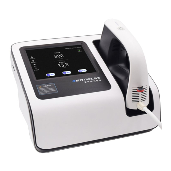
⚫ The fingerprint entry function makes it easy for doctors to quickly retrieve patient information (applicable to KN-5000D). ⚫ The light source calibration system enhances the reliability of the dose emission (applicable to KN-5000D). 2.2 Structural composition The equipment consists of a host equipment and a treatment handle. Treatment handle Host... - Page 22 Figure 2-1 2.2.1 Illustration of the complete machine The illustration of the host equipment is shown in Figure 2-3. ⑤ ④ ① ③ ⑦ ⑥ ② Figure 2-3...
- Page 23 Tap the screen directly for software ① Touch screen operation. ② Treatment handle holder Place the treatment handle ③ Treatment handle Transfer UV light to the skin Press to turn on the light source. The Power button of the light ④...
- Page 24 2.2.2 Rear panel ① ④ ⑤ ③ ② Figure 2-4 ① Fuse Protects the input power of the equipment Power “On” and “Off” control button, ② Power switch when it is set to I, the green indicator will light up Connect to AC power through a three-core ③...
-
Page 25: Identifier Declaration
2.3 Identifier declaration Note! Please refer to the document supplied with the equipment. Please wear goggles Pay attention to ultraviolet radiation protection Turn on the main power Turn off the main power Turn on the light source Protective ground Type B application part identifier Please refer to the instruction for use Product serial number... -
Page 26: Characteristic Parameters
Sign of out-of-service electronics recycling Production date NOTICE: UV emitted from this product. Minimize exposure to eyes or skin. Use appropriate shielding. Wavelength: 308nm±2nm UV irradiation intensity Range≤ 200mW / cm IEC 60601-2-57:2011; IEC 62471:2006 2.4 Characteristic parameters 2.4.1 Classification Classification by type of electric shock protection: Class I ⚫... - Page 27 (mixed with air) or flammable anesthetic gas (mixed with oxygen or nitrous oxide). 2.4.2 Main performance indicators Power supply: AC 100-240V, 50/60Hz ± 2% ⚫ Input power: KN-5000C: 160VA, KN-5000D: 200VA ⚫ Specification, model and rating of fuse: T3.0AL/250V Ф5*20 ⚫ Working environment: temperature: 5~35℃, relative humidity: ≤...
-
Page 28: Installation
If any damage is found, please contact the transportation company or Kernel immediately. ⚫ If the package is intact, carefully remove the equipment and its accessories from the box and place them in a safe, stable, and easy-to-observe position. -
Page 29: Environmental Requirements
mechanical damage, and the accessories are complete. Note! Please save the packaging box and packing materials for later transportation or storage. Warning! ⚫ Packaging materials should be placed out of reach of children. When handling the packaging materials, the relevant local regulations or the waste disposal system of the hospital shall be observed. -
Page 30: Power Requirements
Relative humidity: ≤85%; Atmospheric pressure: 700hPa ~ 1060hPa ⚫ The environment in which the equipment is used should also reasonably avoid the presence of noise, vibration, dust, corrosive or flammable, explosive materials. ⚫ Allow sufficient space around the equipment and leave at least 30cm of space on the rear panel to ensure proper ventilation. - Page 31 Warning! ⚫ Please ensure that the equipment works under the specified environmental requirements and power requirements, otherwise it will not be able to meet the normal working requirements, and may lead to unpredictable consequences such as equipment damage. ⚫ The equipment must be connected separately to a power socket and the socket must not be shared with other electrical equipment.
-
Page 32: Connection
3.4 Connection 3.4.1 Connecting AC Power ⚫ Please confirm that the three-core power wire used is in accordance with the factory configuration. ⚫ Insert one end of the power wire into the AC outlet on the rear panel of the equipment. ⚫... - Page 33 3.4.2 Connect the treatment handle Align the dots Figure 3-1 Insert the cable of the treatment handle into the “treatment handle” slot on the back of the equipment. Note! The handle should be inserted and removed only after the power is turned off.
- Page 34 3.4.3 Installation of micro SD card micro SD Figure 3-2 ⚫ Insert the micro SD card into the “micro SD” slot on the side of the equipment with the direction as shown in the figure. ⚫ When taking out the card, push it inward and the card will pop up automatically.
- Page 35 power is turned off. ⚫ If the micro SD card is not installed or installed well, it will affect the use of the user information management function. The micro SD card can only be copied when it is read by a computer. The content in the card is not allowed to modify at will.
- Page 36 Figure 3-3 Aperture:Φ16 Φ26 Φ36 26×16 36×26 37.2×37.2 Figure 3-4 Specification of the handle hood (mm) The effective irradiation area is a square of 20 cm (45*45 mm) when the hood is not installed. In addition, there are six kinds of treatment handle hoods to choose from.
-
Page 37: Operation
4 Operation 4.1 Preparation before treatment 4.1.1 Preparation for treatment Doctor The dermatologist establishes a treatment plan based on the patient’s condition to determine the treatment site and the initial treatment dose, duration and interval of phototherapy. Patient - Expose the area that needs irradiation and clean the skin. - Apply a lubricating paste to the area that needs irradiation, if necessary. - Page 38 For newly diagnosed patients, a skin phototoxicity test should be — performed, that is perform the minimum erythema dose (MED) test based on the type of UV band used. The MED test Use the biological dose (MED) as the dosage unit for UV treatment due to significant individual differences in UV sensitivity.
- Page 39 Turn the power switch to the “I” position to check if the equipment can work properly. Install the hood on treatment handle Select the hood according to the size of the treatment area, disinfect the hood and install it in the front end of the handle. Please refer to the section 3.4.4.
- Page 40 Figure 4-1 Calibration For the equipment with calibration function, enter the calibration interface and follow the steps for calibration. Please refer to the section 4.3.5. Method of turn off the equipment If the equipment is not used for a long time, please turn the switch to the “○”...
- Page 41 — If the light source is turned on for a long time, the inside of the treatment handle will generate more heat. So please turn off the power switch after the handle cools down completely. Notes: When the equipment is turned on, placed or turned off, the irradiation is not activated and the treatment handle will not emit the UV irradiation.
- Page 42 Make sure that both the doctor and the patient wear UV protective goggles before starting treatment. Individual response The irradiation dose must be adjusted based on the individual response of the patient. The skin response of the previous treatment must be checked and some adjustments should be made accordingly before each new treatment.
- Page 43 improved after continuous treatment. Protection after treatment UV irradiation treatment can cause dry skin. After treatment, apply some soothing oil to the treatment area and avoid excessive sun exposure. Solar dermatitis After the start of phototherapy, if the patient has a large area of solar dermatitis, please check whether the patient receives excessive sunlight, or takes a photosensitizer, or stops using the opacifier.
-
Page 44: Control Panel
pigmentation changes, dry skin, decreased elasticity, solar keratosis and nevoid lentigo, etc. Therefore, both the doctor and the patient should carefully observe the skin condition and changes in the beginning of and during the treatment, and adjust the treatment plan in time. 4.2 Control panel The main interface is shown in Figure 4-2: System... - Page 45 User informatio Status indicator of light source working life Function button Treatment button Figure 4-2 After the equipment is turned on, it will enter the preparation interface, and enter the main interface after 15 seconds. The software operation adopts the touch screen technology, and the corresponding operation can be performed by directly touching the button in the...
- Page 46 interface. ⚫ Definition of the operation buttons: Review and manage the user treatment information. Please refer to the section 4.3.3. for details. Press the button to enter the MED test interface. Please refer to the section 4.3.1. for details. Press the button to enter the setting interface. Please refer to the section 4.3.4.
- Page 47 Press the button to stop the UV output. Please refer to the section 4.3.2. for details. ⚫ Light source working life ➢ Green: The working time of the light source is ≤300 hours and the light source can be used normally. ➢...
- Page 48 ➢ Numeric keypad: Click numbers directly to enter numbers, click "←" to backspace, click "√" to save the input and exit the keyboard. Figure 4-3 ➢ Full keyboard:...
- Page 49 Figure 4-4 ✓ Click the button directly to enter the characters showed on the lower part of the button. ✓ Press the "Shift/Cap" button and then click the corresponding characters to enter capital letters and the characters showed on the upper part of the button. ✓...
-
Page 50: Software Operation
Chinese characters. Click the "←", "→" button to perform the page turning operation when selecting characters. ✓ Enter English characters: Click the English characters and press "Enter" to confirm. ✓ If the input is completed and the cursor still flashes, press “Enter” to cancel the cursor. - Page 51 treatment dose. Phototoxicity test steps: ⚫ ① Determine the patient's skin type according to Table B-1 in Appendix B and select the appropriate skin type. ② Doctors and patients should wear the UV goggles during the test. ③ Install a hood of ф16mm for the treatment handle. ④...
- Page 52 Figure 4-5 ⑤ Mark the position of each hole with a marker or by other means. ⑥ For the next 24 hours, the test site should be protected from any artificial and natural UV light source. ⑦ After 24 hours, the patient should go back to the hospital. ⑧...
- Page 53 Figure 4-6 ⑨ Determine the dose that first cause erythema, and the dose is the minimum phototoxic dose or the minimum erythema dose of the patient. ⑩ If there is severe erythema or blisters in the test site, topical corticosteroids can be used. For example, in Figure 4-6, the patient's skin type is III, and the patient accepted the MED automated test by the equipment that emitting six different doses of UVB automatically (for dose values, please refer to the...
- Page 54 The equipment provides the following two methods of test, i.e. automatic test and manual test. Press the “MED Test” button on the main interface to enter the MED test. As shown below: Figure 4-7 Automatic test ➢ Depending on the type of skin selected, the equipment will perform...
- Page 55 the test according to the preset six output doses. (For specific preset doses and irradiation sequences, please refer to the Appendix C) Click the “CHOOSE SKIN TYPE” box and press the “ ” or “ ” button to select the skin type (I~VI) according to the sun reaction and skin color (please refer to the Appendix B).
- Page 56 Manual test ➢ In the manual test, the doctor can set the six output doses manually. Set the “CHOOSE SKIN TYPE” to “Manual” , click the “Dose” box, the keyboard will be showed, and enter the dose value. The input range is from 80mJ/cm to 600mJ/cm The test method is the same as "automatic test".
- Page 57 “Time” treatment mode “Dose” treatment mode Figure 4-8 ➢ Treatment mode selection: Click the “Setting” button and select the treatment mode on the “Setting” interface (please refer to the section 4.3.4). ✓ Time treatment mode: Click the “TREATMENT TIME” value and press the “...
- Page 58 ✓ Due to the different intensity, the upper limits of "time" and "dose" can be set are different. The "time" is not more than 120 seconds, and the "dose" is not more than 5000 mJ/cm ➢ Press the “Ready” button and prepare to start the UV light output. Press the “ON”...
- Page 59 Figure 4-9 ➢ Press the “Pause” button to pause the UV light output and the “TREATMENT TIME” or “TREATMENT DOSE” counting down. Press the “Ready” button and the “ON” button on the handle to continue the UV light output and “TREATMENT TIME” or "TREATMENT DOSE" counting down.
- Page 60 work until the temperature drops to a safe temperature. ➢ In the stop state, if you need to recall the last set irradiation time, press the “Ready” button to directly recall the last set dose or time. Press the “ON” button on the handle to start the light output. 4.3.3 User information Press the “User Information”...
- Page 61 ➢ Search: Click the blank space after “Name/Patient ID” to enter the keyword in “Name” or “Patient ID” , and click “SEARCH” to display the result of user information in the list. ➢ Treatment: Select a piece of user information, click “Treatment”, the equipment will directly recall the last treatment record of the user to start a new treatment.
- Page 62 Figure 4-11 *** Fingerprint entry (only applicable to KN-5000D models): Click “ Fingerprint ” , the user places his/her finger on the fingerprint recorder according to the prompts. The equipment will save the fingerprint information after three times of entry are made correctly. After completing the fingerprint entry for the user information, a fingerprint icon will be shown in front of the information.
- Page 63 interface. In the interface, the date, time, screen brightness, sound, calibration reminder and treatment mode can be modified. Click the "Date", "Time" or "Screen Brightness" display box, the " ” and " " symbols will appear on the upward and downward side, click " ”...
- Page 64 Turn the button sound on or off. ➢ Calibration reminder Open the reminder Close the reminder Select “On” to remind the user to calibrate the equipment each time it is turned on. This feature is only available for equipment with automatic calibration function.
- Page 65 default password is "654321". You can turn on or turn off and change the password. ✓ Permission password setting: Set the administrator password. The default password is "500021". ➢ Fingerprint management (applicable to KN-5000D) Click “Fingerprint Management”, enter the password and enter the following interface to manage the advanced user fingerprint.
- Page 66 Figure 4-13 ✓ New: Create a new advanced username. ✓ Permission: Select the advanced user to set the permissions of the advanced user, such as "Enable Power on Password", "Delete Treatment Records", and "Delete Cases". "ON" means the permission is turned on and "OFF" means the permission is turned off. ✓...
- Page 67 Click "Irradiation Intensity Calibration" to adjust the calibration value manually or automatically. ✓ Manual adjustment calibration (applicable to KN-5000C): Measure the irradiation intensity at the light output holes with a professional irradiation intensity measurement tool at the source output state. Click "Irradiation Intensity Calibration", enter "Intensity setting password"...
- Page 68 Warning! ⚫ The factory setting of irradiation intensity values are shown in Appendix A. The irradiation intensity value should be corrected according to the measurement results. Please do not modify it arbitrarily to avoid inaccurate dose or time. ✓ Automatic calibration (applicable to KN-5000D): Click “Irradiation calibration”...
- Page 69 Figure 4-15 Warning! ⚫ During the calibration process, the interface will show “Calibrating” with voice prompt, and the equipment will have UV light output. Attention should be paid to UV light Successful calibration: protection at this moment. After the calibration is successful, the equipment prompts that the calibration is complete, click “Confirm”...
- Page 70 If the handle is skewed and not properly inserted (as shown below), calibration will fail or be inaccurate after the calibration is initiated. Figure 4-16 If the prompt “Calibration Failed” is displayed, adjust the handle position as shown in Figure 4-14 to restart the calibration procedure. The result of the calibration performed without the handle being properly inserted, is not accurate, even if the calibration is passed.
- Page 71 calibration still fails, it may be caused by uncleanness in the handle or loss of light source. Please clean the handle according to section 5.3 and calibrate again. If the calibration still fails, the treatment handle needs to be replaced. Please contact the supplier or manufacturer in time to avoid affecting the normal use.
-
Page 72: Maintenance
Maintenance In order to ensure the normal operation and extend the service life of the equipment, please pay attention to the daily check and maintenance of the equipment. 5.1 Inspection In order to ensure the normal and safe operation of the equipment, the equipment and its accessories should be subjected to a preventive inspection (including performance inspection and safety inspection) and maintenance, before the equipment is used and used for 6 months, after... - Page 73 patients, and meets the accuracy required for clinical use. The items to be inspected should include: ✓ The environment and power supply meet the requirements. ✓ The shell of the equipment is clean and free of stains. ✓ There are no mechanical damages to the shell, buttons, connectors and accessories.
-
Page 74: Maintenance
5.2 Maintenance ⚫ Pay attention to the local grid voltage fluctuations. If it is outside the allowable range, it is recommended to add voltage regulator equipment. ⚫ The shell of the equipment should not be opened without permission, to avoid undue malfunction that may affect the normal use. ⚫... -
Page 75: Cleaning
⚫ When the service life of the equipment and accessories expires, it should be handled in accordance with the relevant provisions of electronic product waste. 5.3 Cleaning Warning! ⚫ Before cleaning the equipment, turn off the power switch and disconnect the power wire from the outlet. ⚫... - Page 76 ⚫ Dry the surface with a soft and dry cloth after wiping. ⚫ Place the equipment in a cool and ventilated environment. ⚫ If the transparent baffle of treatment handle is contaminated with dust, wipe it with a soft and lint-free cloth, and then clean the surface with a clean and soft cloth.
-
Page 77: Disinfection
5.4 Disinfection ⚫ The hood of the treatment handle should be disinfected before treatment. It can be immersed into 75% alcohol for 30 minutes, and then dry the surface with a clean and soft cloth. ⚫ If the hood is not installed, wipe the outer surface of the transparent baffle for 30 minutes to have it disinfected by using a soft cloth with 75% alcohol. -
Page 78: Transportation And Storage
5.6 Transportation and storage Transportation The equipment should be protected from rain and snow, and transported by any means of transportation without mixing with corrosive substances or gases. Storage Completely packaged products should be stored in a warehouse which is dry, ventilated, free of corrosive materials and strong magnetic fields. -
Page 79: Fuses Replacement
5.7 Fuses replacement Warning! ⚫ Before replacing the fuse, turn off the power switch and disconnect the power wire from the outlet. Figure 5-2 Figure 5-3 Figure 5-4 As shown in Figure 5-2, turn the fuse holder counterclockwise with a screwdriver to remove the fuse (as shown in Figure 5-3). -
Page 80: Common Failures Analysis And Exclusion
6 Common failures analysis and exclusion The analysis and exclusion methods for common failures of the equipment are shown in Table 6-1. If you are unable to judge or solve the equipment failure, please call the after-sales service center of our company (please refer to the Chapter 7 for details). - Page 81 Incorrect external Check if the power connection The power indicator is power of the network is correct and off after power on. connection. the power wire is intact. The indicator on the Fuse breakdown Replace the fuse power switch is on Please contact after...
- Page 82 The cables of the Reconnect the cables of the handle handle after shutting down connected the equipment Shows "The lamp is not lighted up or the The button of the Please contact lamp during handle manufacturer. irradiation”. breakdown Please contact Lamp breakdown manufacturer.
- Page 83 Shows "The lamp temperature ballast system is Shut down and cool down for of the lamp ballast overheated a while before reusing. is too high. abnormally" Software failures Shut down and restart The cables of the Reconnect the cables of the Shows "The handle handle after shutting down...
-
Page 84: After Service
7 After Service In case of any special requirements for the services, the user can consult relevant issues with the After-sales Service Center of the Company Relevant technical data of the instrument can be provided to the technical service staff authorized by the Company as necessary. The Company will not offer free warranty services for faults as a result of the following causes: ⚫... - Page 85 ⚫ Damage to the instrument and accessories due to human causes. ⚫ Faults due to maintenance without permission of the Company. ⚫ Faults or damage due to force majeure such as fire or earthquake.
-
Page 86: Appendix A Irradiation Intensity
Appendix A Irradiation intensity The nominal values of the irradiation intensity before leaving the factory are recorded in the table below. Table A-1 Irradiation intensity nominal value Band type Irradiation intensity (mW/cm Note: The working life of the light source is not less than 500 hours. After a period of use, the irradiation intensity value will be correspondingly attenuated. - Page 87 function, please contact the distributor or manufacturer. The light source is not allowed to be replaced by the user. If you need to replace the light source, please contact the distributor or manufacturer.
-
Page 88: Appendix B Skin Type
Appendix B Skin type According to regional and population differences, the human skin all over the world can be roughly divided into six types (I to VI). Determine the skin type I to IV by asking the patient about the skin reaction after 30 minutes sunlight exposure at noon in the early summer. -
Page 89: Appendix C Preset Output Dose Of The Med Skin Test
Never have sunburn, Dark eyes, no skin spots, dark brown hair, easy to have tanning light brown skin Brown skin Black skin Appendix C Preset output dose of the MED skin test During the MED test, the equipment will output the UVB dose with the doses sequence in Table C-1 automatically, according to the selected skin type. - Page 90 The above data is the six groups of doses that are automatically emitted for different skin types during automatic MED test (for reference only). If different doses are required, it should be decided by the doctor according to the specific clinical requirements, please refer to the operation method of manual test in section 4.3.1 Phototoxicity Test.
-
Page 91: Appendix D Conversion Of Irradiation Dose/Irradiation Time
Appendix D Conversion of irradiation dose/irradiation time The irradiation time and the irradiation dose can be converted by the following equation: 1. If the unit of the irradiation dose is J/cm , please choose Equation 1: Irradiation time[s] = dosage[J/cm ] X 1000 Intensity [mW/cm 2. - Page 92 J/cm 1000 Irradiation time = ≈ 89(s) mW/cm That is, the required irradiation time is about 89 seconds. 2) If the required irradiation dose is 200 mJ/cm , it can be calculated using Equation 2: 00mJ/cm Irradiation time = mW/cm ≈...
-
Page 93: Appendix E Patient Log
Appendix E Patient log Patient ID: Name: Age: Cumulat Prescr Medic Irradiatio Docto Irradi iption Irradi Skin n time r’s irradiati ation dose ation reac exami ment (minutes/ assess on time date (J/cm site tion nation second) ment (hour/m date inutes) - Page 94 Record the patient log can help the attending doctor to understand the treatment process in time and provide a reference for the next treatment. The log table given in Appendix E is for reference only and can be modified by the user according to the actual usage.
-
Page 95: Appendix F Electromagnetic Compatibility Statement
Appendix F Electromagnetic compatibility statement 1 Precautions: ⚫ This equipment is intended to be used only by health care professionals. The equipment may cause radio interference or disrupt the operation of nearby equipment. If there is any interference, please adjust the direction or position of the equipment. ⚫... - Page 96 the equipment, so the equipment on using state should not close to mobile phones, microwave ovens and other devices that can generate strong magnetic fields. If the equipment is intended to be used in an electromagnetic environment where the radio frequency disturbance controlled, place equipment...
- Page 97 provided in the table below to ensure a normal working environment. 2 Basic performance: ⚫ UV radiation spectrum: Peak wavelength 308 nm, error±2 nm ⚫ UV radiation intensity range: not more than 200mW / cm...
- Page 98 Guidance and manufacturer’s declaration - electromagnetic emission - for all equipment and systems Guidance and manufacturer’s declaration – electromagnetic emission 308nm Excimer System is intended for use in the electromagnetic environment specified below. The customer or the user of 308nm Excimer System should assure that it is used in such an environment.
- Page 99 /flicker emissions EN buildings used for domestic purposes. 61000-3-3 Guidance and manufacturer’s declaration - electromagnetic immunity - for all equipment and systems Guidance and manufacturer’s declaration — electromagnetic immunity 308nm Excimer System is intended for use in the electromagnetic environment specified below.
- Page 100 61000-4-5 ±2 kV common ± 2 kV common commercial or hospital mode mode environment. < 5 % UT < 5 % UT Mains power quality should Voltage dips, (>95 % dip in UT ) (>95 % dip in UT ) be that of a typical short for 0.5 cycle...
- Page 101 life-supporting Guidance and manufacturer’s declaration - electromagnetic immunity 308nm Excimer System is intended for use in the electromagnetic environment specified below. The customer or the user of 308nm Excimer System should assure that it is used in such an environment. Immunity EN 60601 test Compliance...
- Page 102 less than the compliance level in each frequency range.b Interference may occur in the vicinity of equipment marked with the following symbol: NOTE 1 At 80 MHz and 800 MHz, the higher frequency range applies. NOTE 2 These guidelines may not apply in all situations. Electromagnetic is affected by absorption and reflection from structures, objects and people.
- Page 103 System can help prevent electromagnetic interference by maintaining a minimum distance between portable and mobile RF communications equipment (transmitters) and 308nm Excimer System as recommended below, according to the maximum output power of the communications equipment Rated Separation distance according to frequency of transmitter (m) maximum output of transmitter...
-
Page 104: Kn-5000C Packing List
NOTE 1 At 80 MHz and 800 MHz, the separation distance for the higher frequency range applies. NOTE 2 These guidelines may not apply in all situations. Electromagnetic propagation is affected by absorption and reflection from structures, objects and people. KN-5000C Packing List Name Quantity Unit... -
Page 105: Kn-5000D Packing List
Power cord Fuse micro SD card Mainframe Dust Cover Cleaning cloth Hand Strap Instructions KN-5000D Packing List Name Quantity Unit Mainframe Therapeutic handle Therapeutic Handle Mask (6 sizes) Goggles... - Page 106 Power cord Fuse micro SD card Mainframe Dust Cover Cleaning cloth Hand Strap Instructions...
- Page 107 Contact information: Company Name: Xuzhou Kernel Medical Equipment Co., Ltd. Company Address: Kernel Mansion, Economic Development District, Xuzhou City, Jiangsu Province, China Zip Code:221004 Tel: +86(516)87732209 Fax:+86(516)87732210 Web:www.kernelmed.com www.kerneluvb.com Email:admin@kernelmed.com EU representative: Company Name:Prolinx GmbH Company Address: Brehmstr. 56, 40239, Duesseldorf ,Germany Tel:0049 211 3105 4698...
- Page 108 2460...
Need help?
Do you have a question about the KN-5000C and is the answer not in the manual?
Questions and answers