
Related Manuals for Generac Power Systems MOBILEPOWER MMG130D


Summary of Contents for Generac Power Systems MOBILEPOWER MMG130D
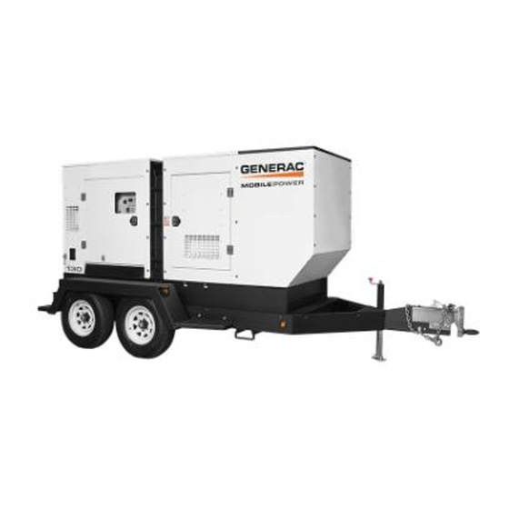
- Page 1 DIESEL GENERATOR MMG130D • MMG175 • MMG205 POWER PRODUCTS LLC Manufactured by A wholly owned subsidiary of Generac Power Systems, Inc. OPERATING MANUAL Parts manuals available online! www.m-p-llc.com...
-
Page 2: Introduction
INTRODUCTION This manual provides information and procedures to safely operate and maintain the engine and generator. For your own safety and protection from physical injury, carefully read, understand, and observe the safety instructions described in this manual. The information contained in this manual was based on machines in production at the time of publication. -
Page 3: Table Of Contents
TABLE OF CONTENTS Page INTRODUCTION ..........................2 SAFETY NOTES ..........................6 OPERATING SAFETY ........................6 ENGINE SAFETY..........................7 ELECTRICAL SAFETY ........................7 TOWING SAFETY..........................8 REPORTING TRAILER SAFETY DEFECTS ..................8 SAFETY SYMBOL SUMMARY ......................9 SPECIFICATIONS - MMG130D ....................... 10 SPECIFICATIONS - MMG175...................... - Page 4 JACK MAINTENANCE ........................46 CHECKING GENERATOR DRIVE PLATE TORQUE ..............47 AUXILIARY FUEL TANK OPTION ....................47 FUEL TRANSFER PUMP OPTION....................48 VISCOUS FAN CLUTCH OPTION....................48 AC WIRING DIAGRAM - MMG130D, MMG175 ................49 AC WIRING DIAGRAM - MMG205 ....................50 AC WIRING DIAGRAM - 4-POS.
- Page 5 This Page Intentionally Left Blank...
-
Page 6: Safety Notes
SAFETY NOTES This is the safety alert symbol. It is used to alert you to potential personal injury hazards. Obey all safety messages that follow this symbol to avoid possible injury or death. This manual contains DANGERS, WARNINGS, CAUTIONS, NOTICES and NOTES which must be followed to prevent the possibility of improper service, damage to the equipment, personal injury or death. -
Page 7: Engine Safety
ENGINE SAFETY Internal combustion engines present special hazards during operation and fueling! Failure to follow the safety guidelines described below could result in severe injury or death. Read and follow all safety warnings described in the engine operator's manual. A copy of this manual was supplied with unit when it was shipped from the factory. -
Page 8: Towing Safety
TOWING SAFETY Towing a trailer requires care! Both the trailer and vehicle must be in good condition and securely fastened to each other to reduce the possibility of an accident. Also, some states require that large trailers be registered and licensed. Contact your local Department of Transportation office to check on license requirements for your particular unit. -
Page 9: Safety Symbol Summary
SAFETY SYMBOL SUMMARY This equipment has been supplied with numerous safety and operating decals. These decals provide important operating instructions and warn of dangers and hazards. Replace any missing or hard-to-read decals and use care when washing or cleaning the unit. Decal placement and part numbers can be found in the parts manual. Below is a summary of the intended meanings for the symbols used on the decals. -
Page 10: Specifications - Mmg130D
SPECIFICATIONS - MMG130D Read this manual carefully before attempting to use this generator. The potential for property damage, personal injury or death exists if this equipment is misused or installed incorrectly. Read all of the manuals included with this unit. Each manual details specific information regarding items such as setup, use and service requirements. SPECIFICATIONS ARE SUBJECT TO CHANGE WITHOUT NOTICE. -
Page 11: Specifications - Mmg175
SPECIFICATIONS - MMG175 Read this manual carefully before attempting to use this generator. The potential for property damage, personal injury or death exists if this equipment is misused or installed incorrectly. Read all of the manuals included with this unit. Each manual details specific information regarding items such as setup, use and service requirements. SPECIFICATIONS ARE SUBJECT TO CHANGE WITHOUT NOTICE. -
Page 12: Specifications - Mmg205
SPECIFICATIONS - MMG205 Read this manual carefully before attempting to use this generator. The potential for property damage, personal injury or death exists if this equipment is misused or installed incorrectly. Read all of the manuals included with this unit. Each manual details specific information regarding items such as setup, use and service requirements. SPECIFICATIONS ARE SUBJECT TO CHANGE WITHOUT NOTICE. -
Page 13: Unit Dimensions
UNIT DIMENSIONS Read this manual carefully before attempting to use this generator. The potential for property damage, personal injury or death exists if this equipment is misused or installed incorrectly. Read all of the manuals included with this unit. Each manual details specific information regarding items such as setup, use and service requirements. SPECIFICATIONS ARE SUBJECT TO CHANGE WITHOUT NOTICE. -
Page 14: Unit Serial Number Locations
UNIT ID Tag Manufactured by MAGNUM POWER PRODUCTS LLC A wholly owned subsidiary of Generac Power Systems, Inc. 215 Power Drive • Berlin, WI 54923 1-800-926-9768 Model Serial Number VIN Tag Mfg. -
Page 15: Component Locations
COMPONENT LOCATIONS Central Lift Point Engine Voltage Selector Access Switch Fuel Fill Engine Battery Access Ladder Radiator Access Panel Engine Exhaust Ladder Engine Control Access Panel Access Emergency Radiator Oil Drain Stop Drain Port Port... -
Page 16: Main Control Panel Features
MAIN CONTROL PANEL FEATURES DISABLE AUTO EXHAUST AUSSCHALTEN DESACTIVAR FILTER CLEANING DÉSACTIVER AUTOMATISCHE ABGASFILTERREINIGUNG LIMPIEZA AUTOMÁTICA ENABLE DE FILTRO DE ESCAPE EINSCHALTEN NETTOYAGE DU FILTRE ACTIVAR D’ÉCHAPPEMENT AUTO ACTIVER... - Page 17 1. DOCUMENT HOLDER 2. AIR FILTER METER: This gauge shows the condition of the air filter when the engine is running. 3. MAGNUM DIGITAL CONTROLLER (MDC): Refer to “Magnum Digital Controller (MDC)” on page 4. AUXILIARY LIGHT SWITCHES (Optional): These switches operate the control panel and interior lights. 5.
-
Page 18: Main Control Panel Features - With Cam Lock Option
MAIN CONTROL PANEL FEATURES - WITH CAM LOCK OPTION OPERATION CONTROL CONTROL MAN AUT MANUAL AUTO ENGINE ENGINE START START Ready PF 0.00 RPM 0 CONTROL CONTROL ALARM FAULT ENGINE ENGINE CANCEL RESET STOP STOP DIAGNOSTICS STATUS PAGE ALARM/FAULT WARNING SELECT READY/MANUAL READY/AUTO... - Page 19 1. DOCUMENT HOLDER 2. AIR FILTER METER: This gauge shows the condition of the air filter when the engine is running. 3. MAGNUM DIGITAL CONTROLLER (MDC): Refer to “Magnum Digital Controller (MDC)” on page 4. AUXILIARY LIGHT SWITCHES (Optional):These switches operate the control panel and interior lights. 5.
-
Page 20: Magnum Digital Controller (Mdc)
MAGNUM DIGITAL CONTROLLER (MDC) The Magnum Digital Controller (MDC) is an enhanced digital generator controller used to start, stop and monitor the operation of the generator and the engine. The controller constantly monitors vital generator and engine functions for a number of pre-programmed alarm and fault conditions. When a fault condition occurs, the engine will shut down automatically and the Liquid Crystal Display (LCD) window will display the fault that caused the shutdown;... -
Page 21: Generator Monitoring
• “FAULT RESET” Button: Press this button to clear the fault from the LCD window after the fault has been corrected. Press “FAULT RESET” and “ENTER” to clear the John Deere ECU Alarm List Codes. 3. The Liquid Crystal Display (LCD) •... -
Page 22: Engine Monitoring
ENGINE MONITORING Engine information is shown on the Liquid Crystal Display (LCD) window in a toggling manner with the generator information after the first 60 seconds of operation, and then every five seconds. The engine display screen will show oil pressure, engine coolant temperature, fuel level and battery voltage. •... -
Page 23: Diesel Exhaust Filter Monitoring
• “Password” screen: The operator may press the “” or “” buttons on the “DIAGNOSTICS” keypad to move the “>” cursor up or down a list of text. • “History” screen: The operator may press the “” or “” buttons on the “DIAGNOSTICS” keypad to move the “>”... -
Page 24: Wet Stacking
disabled, this area may also display a “Yellow Alarm” (“Warning”) or a “Red Alarm” (“Stop”) indicator with the “Regeneration” indicator in order to alert the operator that regeneration is needed. • “DPF Inhib” area: This area will display the “Disabled Regeneration” indicator above the words “DPF Inhib” when auto exhaust filter cleaning is disabled. -
Page 25: Fine Voltage Adjustment
FINE VOLTAGE ADJUSTMENT Upon startup of the generator, the “Running” screen of the Magnum Digital Voltage Controller (MDC) will display “V Detect” and will countdown from 45 seconds CONTROL Adjustment to zero. This is a safety feature of the controller to protect the generator from Screw over or under voltage upon startup. -
Page 26: Engine Break-In Requirements
Are any of the generator covers loose or missing? Are all preventive maintenance procedures up to date? Check that the battery disconnect switch is on, if equipped. ENGINE BREAK-IN REQUIREMENTS Note: During the first 20 hours of operation, avoid long periods of no load or sustained maximum load operation. If the generator is to run for longer than five minutes without a load, shut the generator down. - Page 27 4. Press the green “ENGINE START” button. The “Prestart” screen will be displayed (if equipped) and a countdown will begin from 20 seconds to 0. 5. The “Starting” screen will be displayed. The engine will crank and start running. 6. The “Running” screen will display. Note: It may take a few seconds for the engine to run smoothly and reach its governed operating speed.
-
Page 28: Auto" (Remote) Starting Of The Generator
up and the LCD window will show engine and generator operating parameters. Temperature will be shown as “0” until the engine temperature is approximately 100°F (38°C). 11. Check the generator for excessive noise or vibration and any coolant, oil, or fuel leaks before applying any loads. 12. -
Page 29: Exhaust Filter Cleaning Operations
EXHAUST FILTER CLEANING OPERATIONS When enabled, the exhaust filter system goes through an automatic cleaning process known as regeneration. Under normal circumstances, regeneration occurs without interruption of unit operation and with minimal operator involve- ment. In the event there are conditions requiring the operation of the unit with auto exhaust filter cleaning disabled, the operator may be required to perform procedures to enable or disable the auto exhaust filter cleaning. -
Page 30: Mdc Controller Information Displays, Functions, And Reset
MDC CONTROLLER INFORMATION DISPLAYS, FUNCTIONS, AND RESET The Magnum Digital Controller (MDC) constantly monitors vital generator and engine functions for a number of operation, alarm, and fault conditions. When a fault condition occurs, the engine will shut down automatically and the Liquid Crystal Display (LCD) window will show the fault that has caused the shutdown. -
Page 31: Magnum Digital Controller (Mdc) - List Of Alarms
MAGNUM DIGITAL CONTROLLER (MDC) - LIST OF ALARMS Shutdown and warning fault conditions and the displayed message are described in the following table: Information on Events Protection Binary Output Description Specification Type Available Shutdown alarm configurable on the input of IG-IOM/ AnInIOM Sd IGS-PTM. -
Page 32: Magnum Digital Controller (Mdc) - History
Information on Events Protection Binary Output Description Specification Type Available During starting of the engine, when the RPM reaches the value of Starting RPM setpoint, the starter is switched off and the speed of the engine can drop 26 Underspeed under Start RPM again. -
Page 33: Adjusting The Display Backlighting
the unit. To resume operation, the fault condition must be resolved and the code cleared from the display. Figure 1 Diagnostic messages are read and displayed in the ECU Alarm List. The Suspect Parameter Number (SPN)*, Failure Mode Identifier (FMI) and Occurrence Counter (OC) are shown together with a description (if possible). One SPN*/ FMI describes one failure. -
Page 34: Resetting The "Time To Service" Reminder
RESETTING THE “TIME TO SERVICE” REMINDER The Magnum Digital Controller (MDC) will display the message “WrnMaintenance” when the unit is due for maintenance or service. The maintenance or service interval is set at 250 hours of engine running time. Once the unit has been serviced, the “Time to Service”... - Page 35 4. Check the engine oil to verify no coolant has mixed with it (oil will appear milky if coolant is present). Consult the engine operator’s manual for additional information. HIGH COOLANT TEMPERATURE SHUTDOWN 1. Check the coolant level in the overflow jug. 2.
-
Page 36: Generator Output Connection Lugs
GENERATOR OUTPUT CONNECTION LUGS The generator is equipped with connection lugs, located behind the lug box door located on the lower portion of the control box. The lugs provide connection points for attachment of external loads to the generator. A large decal on the inside of the connection lug door details the proper connections for selected voltages. -
Page 37: Generator Cam Lock Connection(S) Option
GENERATOR CAM LOCK CONNECTION(S) OPTION The generator may be equipped with cam lock connections, behind the door on the right side of the customer convenience outlets. These receptacles provide connection points for attachment of external loads to the generator. A large decal on the inside of the connection lug door details the proper connections for selected voltages. WARNING It is HIGHLY RECOMMENDED that only a trained and licensed electrician perform any wiring and related connections to the generator. -
Page 38: Voltage Selector Switch
VOLTAGE SELECTOR SWITCH The voltage selector switch is located on a panel attached to the generator behind the door located next to the fuel tank filler. The selector switch is a three position switch that mechanically changes the connections between the generator output leads and the connection lugs on the main control panel. -
Page 39: 4-Position Voltage Selector Switch Option
4-POSITION VOLTAGE SELECTOR SWITCH OPTION The optional four position voltage selector switch is located on a panel attached to the generator behind the door located next to the fuel tank filler. The voltage selector is a four position switch that mechanically changes the connections between the generator output leads and the connection lugs on the main control panel. -
Page 40: Emergency Stop Switch
EMERGENCY STOP SWITCH The generator is equipped with one “EMERGENCY STOP” switch, located on the right rear corner of the unit next to the control door. The switch is clearly labeled “EMERGENCY STOP” and is red. The switch can be accessed and activated with all doors closed and locked. -
Page 41: Customer Convenience Outlets
CUSTOMER CONVENIENCE OUTLETS The generator is equipped with five convenience outlets. The large outlets are 240/120VAC twist-lock receptacles rated at 50A each. The smaller outlets are 120VAC duplex receptacles rated at 20A each with ground fault circuit interrupt (GFCI) protection. These receptacles are not routed through the main circuit breaker. Each receptacle has its own circuit breaker, located directly above or next to the outlet. -
Page 42: Transfer Switch
TRANSFER SWITCH The generator neutral is bonded to ground when shipped from the factory. The bonding plate will need to be removed when the generator is used as a standby power source. Installation should be in compliance with National Electric Code (NEC), as well as any state and local codes or regulations. -
Page 43: Auto Exercise Timer
AUTO EXERCISE TIMER Generators installed in a standby application should be exercised regularly to maintain operating condition and to ensure responsiveness in an emergency situation. The following procedure demonstrates how to run (exercise) the generator on a time schedule: 1. Press the “PAGE SELECT” button until “Password” appears at the top of the screen. 2. -
Page 44: Basic Maintenance Schedule (John Deere Engine)
• Verify that all circuit breakers are open (“OFF/O”). • Activate (push in) the “EMERGENCY STOP” switch. • Disconnect the negative (-) terminal on the battery. • Attach a “DO NOT START” sign to the control panel. This will notify everyone that the unit is being serviced and will reduce the chance of someone inadvertently trying to start the unit. -
Page 45: Belt Tensioners
Replace primary air cleaner when dust valve restriction indicator gauge shows a vacuum of 25 in. H Change the oil and oil filter after the first 100 hours, then every 500 hours. If not using John Deere Plus 50 II engine oil, the interval must be decreased to every 250 hours. -
Page 46: Towing The Trailer
TOWING THE TRAILER 1. Use the jack to raise or lower the trailer onto the hitch of the towing vehicle. Lock the hitch coupling and attach the safety chains or cables to the vehicle. Raise the jack foot completely. 2. Connect any trailer wiring to the tow vehicle. Check for proper operation of the stop and signal lights. 3. -
Page 47: Checking Generator Drive Plate Torque
TOP-WIND MODELS • Apply a lightweight oil to the screw stem. CHECKING GENERATOR DRIVE PLATE TORQUE Follow the procedure below to check the torque of the generator drive plate bolts in accordance with the maintenance chart. Refer to “Basic Maintenance Schedule (John Deere Engine)” on page 1. -
Page 48: Fuel Transfer Pump Option
FUEL TRANSFER PUMP OPTION The fuel transfer pump option allows the fuel tank to be refilled from an external bulk fuel source. When the fuel transfer switch is on, anytime the fuel level drops below 15% the fuel transfer pump will begin pumping fuel from an external bulk fuel source into the fuel tank on the unit. -
Page 49: Ac Wiring Diagram - Mmg130D, Mmg175
AC WIRING DIAGRAM - MMG130D, MMG175 120V 120V MECHANICAL LUGS GFCI GFCI RECPT RECPT LUG DOOR SAFETY SWITCH 120V 120V BRKER BRKER GROUND GRN/YEL TO GEN FRAME GRN/YEL GRN/YEL GRN/YEL GRN/YEL MAIN CIRCUIT BREAKER WIRES NOT USED IN 240V 240V 50A BUCK BOOST OPTION BREAKER RCPT. -
Page 50: Ac Wiring Diagram - Mmg205
AC WIRING DIAGRAM - MMG205 120V 120V MECHANICAL LUGS GFCI GFCI RECPT RECPT LUG DOOR SAFETY SWITCH 120V 120V BRKER BRKER GROUND GRN/YEL TO GEN FRAME GRN/YEL GRN/YEL GRN/YEL GRN/YEL MAIN CIRCUIT BREAKER WIRES NOT USED IN 240V 240V 50A BUCK BOOST OPTION BREAKER RCPT. - Page 51 AC WIRING DIAGRAM - 4-POS. VOLT. SELECTOR SWITCH OPTION - MMG130D, MMG175...
-
Page 52: Ac Wiring Diagram - 4-Pos. Volt. Selector Switch Option - Mmg130D, Mmg175
AC WIRING DIAGRAM - 4-POS. VOLT. SELECTOR SWITCH OPTION - MMG205... -
Page 53: Ac Wiring Diagrams For Optional Equipment
AC WIRING DIAGRAMS FOR OPTIONAL EQUIPMENT... -
Page 54: Dc Wiring Diagram
DC WIRING DIAGRAM... -
Page 55: Dc Wiring Diagrams For Optional Equipment
DC WIRING DIAGRAMS FOR OPTIONAL EQUIPMENT... -
Page 56: Wiring Block Diagram - Dedicated 12 Lead Generators Option
WIRING BLOCK DIAGRAM - DEDICATED 12 LEAD GENERATORS OPTION... -
Page 57: Trailer Lights Wiring Diagram
TRAILER LIGHTS WIRING DIAGRAM TRAILER PLUG AMBER AMBER MARKER MARKER LAMP LAMP AMBER AMBER MARKER MARKER LAMP LAMP FENDER FENDER IDENTIFICATION MARKER MARKER LIGHT BAR LAMP LAMP PLATE LAMP STOP-TURN STOP-TURN SIGNAL LAMP SIGNAL LAMP (LEFT) (RIGHT) 90386_ORG_05.23.12... -
Page 58: Wiring Harness - Electric Brake Option
WIRING HARNESS - ELECTRIC BRAKE OPTION... -
Page 59: Service Log
SERVICE LOG OIL GRADE AND TYPE: ___________________________ BRAND: ___________________________________ COOLANT MIXTURE: _____________________________ BRAND: ___________________________________ __________________________________________________________________________________________ __________________________________________________________________________________________ __________________________________________________________________________________________ __________________________________________________________________________________________ __________________________________________________________________________________________ __________________________________________________________________________________________ __________________________________________________________________________________________ __________________________________________________________________________________________ __________________________________________________________________________________________ __________________________________________________________________________________________... - Page 60 REV: D PART NO: 29914G 05.28.13...
Need help?
Do you have a question about the MOBILEPOWER MMG130D and is the answer not in the manual?
Questions and answers