
Related Manuals for Generac Power Systems MAGNUM MTT20IF4


Summary of Contents for Generac Power Systems MAGNUM MTT20IF4
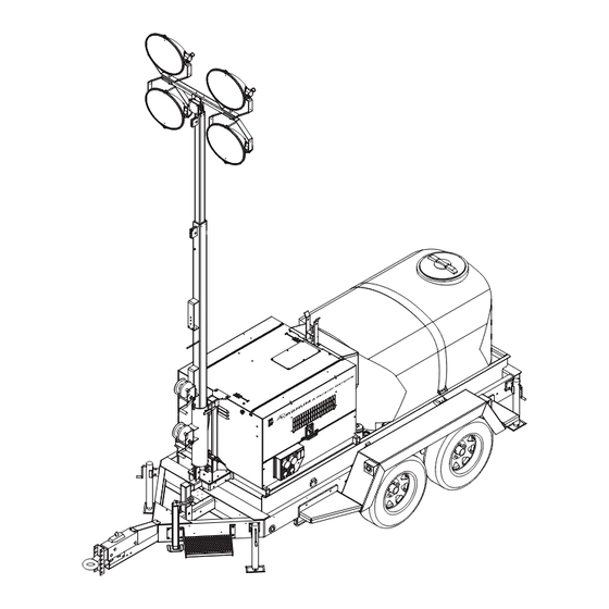
- Page 1 COMBINATION LIGHT TOWER GENERATOR & WATER TRAILER MTT20IF4 00900 OPERATING MANUAL Parts manuals available online! www.magnumpower.com...
-
Page 2: Introduction
INTRODUCTION This manual provides information and procedures to safely operate and maintain the Magnum Power Products LLC unit. For your own safety and protection from physical injury, carefully read, understand, and observe the safety instructions described in this manual. Keep a copy of this manual with the unit at all times. Additional copies are available from Magnum Power Products LLC, or can be found at www.magnumpower.com.The information contained in this manual was based on machines in production at the time of publication. -
Page 3: Table Of Contents
TABLE OF CONTENTS Page INTRODUCTION ..........................2 SAFETY NOTES ..........................5 OPERATING SAFETY ........................5 ENGINE SAFETY..........................6 SERVICE SAFETY..........................7 TOWING SAFETY..........................7 REPORTING TRAILER SAFETY DEFECTS ..................8 SAFETY SYMBOL SUMMARY ......................9 SPECIFICATIONS..........................10 UNIT DIMENSIONS ......................... 11 UNIT SERIAL NUMBER LOCATIONS ..................... - Page 4 DC WIRING DIAGRAM - ELECTRIC WINCH OPTION ..............48 DC WIRING DIAGRAM - INTERIOR LIGHT OPTION ..............49 DC WIRING DIAGRAM - BATTERY DISCONNECT OPTION ............49 DC WIRING DIAGRAM - BATTERY CHARGER OPTION............... 49 TRAILER LIGHTS WIRING DIAGRAM .................... 50 SERVICE LOG ..........................
-
Page 5: Safety Notes
SAFETY NOTES This is the safety alert symbol. It is used to alert you to potential personal injury hazards. Obey all safety messages that follow this symbol to avoid possible injury or death. This manual contains DANGERS, WARNINGS, CAUTIONS, NOTICES and NOTES which must be followed to prevent the possibility of improper service, damage to the equipment, personal injury or death. -
Page 6: Engine Safety
• ALWAYS extend the outriggers and level the unit before raising the mast. DO NOT retract the outriggers while the mast is up. • If for any reason any part of the mast hangs up or the winch cable develops slack while raising or lowering the mast, STOP immediately and contact an authorized service representative. -
Page 7: Service Safety
Protective covers are loose or missing. If the ambient air temperature is above 120°F (49°C). SERVICE SAFETY This unit uses high voltage circuits capable of causing serious injury or death. Only a qualified electrician should troubleshoot or repair electrical problems occurring in this equipment. •... -
Page 8: Reporting Trailer Safety Defects
• When towing, maintain extra space between vehicles and avoid soft shoulders, curbs and sudden lane changes. If you have not pulled a trailer before, practice turning, stopping, and backing up in an area away from heavy traffic. • Towing the unit with water in the tank will adversely affect handling of towing vehicle, specifically maneuvering corners, accelerating, and braking. -
Page 9: Safety Symbol Summary
SAFETY SYMBOL SUMMARY This equipment has been supplied with numerous safety and operating decals. These decals provide important operating instructions and warn of dangers and hazards. Replace any missing or hard-to-read decals and use care when washing or cleaning the unit. Decal placement and part numbers can be found in the parts manual. Below is a summary of the intended meanings for the symbols used on the decals. -
Page 10: Specifications
SPECIFICATIONS MAGNUM MODEL MTT20IF4 Engine Make/Brand..........................Isuzu Model ...........................4LE2TAGV-03 EPA Tier ..........................4f Horsepower - prime hp (kW) ....................36.2 (27.0) Horsepower - standby hp (kW)....................40.2 (30.0) Operating Speed rpm ......................1800 Displacement in (L) ......................133 (2.19) Cylinders - qty ........................4 Fuel Consumption - 100% prime gph (Lph) ................2.1 (7.8) Battery Type - Group Number ....................24 Battery Voltage (Quantity per Unit) ..................12V (1) Battery Rating ........................720 CCA... -
Page 11: Unit Dimensions
UNIT DIMENSIONS 00902 210 in 83 in 31.5 ft 86 in MTT20IF4 (5.3 m) (2.1 m) (9.6 m) (2.18 m) Specifications are subject to change without notice. -
Page 12: Unit Serial Number Locations
Unit ID Tag Located on inside of front panel Manufactured by Magnum Power Products, LLC., a subsidiary of Generac Power Systems, Inc. (920) 361-4442 (800) 926-9768 Country of Origin Model... -
Page 13: Component Locations
COMPONENT LOCATIONS Control Engine / Battery Engine Fuel Water Tank Panel Access Access Exhaust Fill Cover Emergency Stop Switch Receptacle Panel Grounding Stud Leveling Forklift Forklift Leveling Jack Pockets Pockets Jack LEFT SIDE Radiator Access Engine (on roof panel) Access Hose Bibbs Leveling... -
Page 14: Light Tower Set Up
LIGHT TOWER SET UP 1. For maximum light coverage, locate the unit at ground level or in a spot higher than the area being illuminated by the lamps. WARNING The mast extends up to 31.5 ft (9.6 m). Make sure the area above the unit is open and clear of overhead wires and obstructions. -
Page 15: Raising The Mast
RAISING THE MAST 1. Set up and level the unit. Refer to “Light Tower Set Up” on page WARNING The unit must be leveled before raising the mast. Failure to level the unit will severely reduce the stability and could DETAIL A DETAIL C allow the unit to tip and fall. -
Page 16: Raising The Mast With Electric Winch Option
RAISING THE MAST WITH ELECTRIC WINCH OPTION 1. Set up and level the unit. Refer to “Light Tower Set Up” on page WARNING The unit must be leveled before raising DETAIL C the mast. Failure to level the unit will DETAIL D severely reduce the stability and could allow the unit to tip and fall. -
Page 17: Main Control Panel
MAIN CONTROL PANEL MAIN BREAKER 240V BREAKER NEUTRAL BONDED TO FRAME 00896 1. L401 CONTROLLER: Refer to “L401 Controller” on page 2. MAIN CIRCUIT BREAKER: This 240V (100A) breaker will disconnect power to the lights and the receptacles. 3. DC BREAKER: Circuit breaker (10A) for the engine electrical system. 4. -
Page 18: L401 Controller
L401 CONTROLLER The L401 controller is an auto start controller that monitors the unit and indicates operational status and fault conditions. The controller can be programmed to automatically start or stop based on time schedule, fault condition, or load demand. The controller constantly monitors vital generator and engine functions for a number of preprogrammed alarm and fault conditions. - Page 19 Icon Details Generator voltage and frequency screen Current and load screen Engine speed screen Hours run screen Battery voltage screen Oil pressure screen Coolant temperature screen Fuel sender screen Event log Current time held in the unit The current valve of the scheduler run time and duration ECU diagnostic trouble codes Oil filter maintenance timers Air filter maintenance timers...
- Page 20 Icon Details A timer is active (i.e. cranking time, crank rest, etc.) Engine is running, and all timers have expired, either on or off load. The animation speed is reduced when running in Idle mode. Unit is in the front panel editor USB connection is made to the controller Configuration file or engine file is corrupted Light Output Icons...
- Page 21 Icon Fault Description The measured current has risen above the configured trip level for a Delayed Over Current configured duration. The measured current has fallen below the configured trip level. This is Low Current used to detect lamp failure. Oil Filter Maintenance Alarm Maintenance due for oil filter. Air Filter Maintenance Alarm Maintenance due for air filter.
- Page 22 Icon Fault Description The measured current has risen above the configured trip level for a Delayed Over Current configured duration. The measured current has fallen below the configured trip level. This is Low Current used to detect lamp failure. Oil Filter Maintenance Alarm Maintenance due for oil filter. Air Filter Maintenance Alarm Maintenance due for air filter.
-
Page 23: Operator Screens
CAUTION In case of an emergency, always press the emergency stop switch located on the side of the unit to stop the engine immediately. The Stop/Reset (O) button may delay the engine shutdown if stop faults exist. To prevent damage to the generator and connected equipment, remove all loads from the generator by opening all circuit breakers (turn to the OFF (O) position) before pressing the Stop/Reset (O) button. - Page 24 Icon Description Mast and light screens Engine DTCs (Diagnostic Trouble Codes) if active Event log HOME SCREEN The Home screen is the default screen of the controller and will display after the controller has powered up. The controller will automatically return to this screen from any other screen after a period of inactivity. 00897 ENGINE SCREENS The Engine screens will display the speed, run time, battery voltage, coolant temperature, oil pressure, fuel level...
-
Page 25: Prestart Checklist
To exit the active DTC(s) alarm section, press the ↑ and ↓ buttons simultaneously to enter the navigation menu. Once entered, cycle to the desired operator screen. Icon Fault DTC Description The engine ECU has detected a fault not recognized by the con- Check Engine Fault troller, contact the engine manufacturer for support. -
Page 26: Engine Break-In Requirements
Ensure all covers are in place and secure. Ensure the emergency stop switch is pulled out. ENGINE BREAK-IN REQUIREMENTS Note: The EPA final tier 4 Isuzu engines have an engine break-in duration that will prohibit the unit from providing rated standby power upon factory delivery. -
Page 27: Auto (Remote) Starting Of The Unit
4. If the engine does not start after the first cranking attempt, the engine will pause for 15 seconds to allow the starter to cool. The engine will make two more attempts to start for a total of three crank cycles. Note: The controller backlight will go out when the engine is cranking. -
Page 28: Automatic Shutdown
AUTOMATIC SHUTDOWN This unit is equipped with a low oil pressure and high coolant temperature automatic shutdown system. This system will automatically shut off the fuel supply to stop the engine if oil pressure drops too low or the engine exceeds normal operating temperature. -
Page 29: Voltage Regulation
VOLTAGE REGULATION Units are equipped with an electronic voltage regulator. The voltage regulator controls the output of the generator by regulating the current into the exciter field. The regulator has three screwdriver adjustable potentiometers that may be adjusted for voltage, stability and voltage roll-off (U/F). The voltage regulator is adjusted before shipment from the factory. -
Page 30: Remote Start Terminal Block
REMOTE START TERMINAL BLOCK The remote start terminal block provides a connection for installation of a remote start switch which will allow the unit to be started by a remote dry-contact closure switch. Remote Start For location of the remote start terminal block, refer to “Main Control Panel”... -
Page 31: Auto Exercise Timer
WARNING ONLY a licensed electrician should perform wiring or related connections to the generator. Installation should be in compliance with the National Electrical Code (NEC), state and local regulations. Failure to follow these procedures could result in property damage, personal injury or death. Before any connections are attempted, make sure the main circuit breaker and the Control Power switch are in the OFF (O) position and that the negative (-) battery cable has been disconnected from the battery. - Page 32 This table lists the parameters needed to schedule an event and to adjust the clock within the controller. Note: If parameter 902 is “0”, then the auto exercise timer is enabled and if it is “1”, then the autolight timer is enabled. Parameter Description Details...
-
Page 33: Shutting Down The Unit
SHUTTING DOWN THE UNIT Check with personnel using power supplied by the unit and let them know the power is going to be turned off. Make sure the power shut down will not create any hazards by accidentally turning off equipment that needs to be kept on (pumps, compressors, lights, etc.). -
Page 34: Lowering The Mast - Manually
Drain the tank when the temperature is expected to drop below 32°F (0°C) or if the unit is to be stored for a long period of time. TO REFILL THE WATER TANK: 1. Close all hose bibbs. 2. Remove the tank cover; leave the smaller inspection cap in the center of the cover in place. 3. -
Page 35: Removing The Lights For Transportation
4. Release the mast lock by pulling the safety pin on the mast lock and pulling the lock bar free. Lower the mast by holding the lower winch control switch to the right until the mast is resting in the transport cradle. Note: If the mast lock bar does not pull free, activate the lower winch slightly to relieve pressure on the mast bar. -
Page 36: Lifting The Unit
9. Check the wheel lugs. Tighten or replace any lugs that are loose or missing. If a tire has been replaced or removed for axle service, tighten the lugs, in the order shown, to the following specifications: A. Start all lug nuts by hand. B. -
Page 37: Basic Maintenance Schedule - Isuzu Engine
• Check that winch cables are in good condition PROPER MAST CABLE ROUTING and are centered on each pulley. DO NOT use a cable that is kinked or starting to unravel. • Check that the safety pins for the mast lock rod and mast lock bar are present and secured with a chain. -
Page 38: Resetting The Maintenance Alarms
1000 Item Daily Hours Hours Hours Check Fan Belt Tension (Replace If Necessary) Oil Filter Element Replacement Replace Air Filter Element Lubricate Leveling Jacks Replace Heated Fuel Filter (If Equipped) Inspect Engine Starting Battery RESETTING THE MAINTENANCE ALARMS The L401 controller will display a warning message when the unit is due for maintenance or service. -
Page 39: Winch Use, Operation & Maintenance - Electric
3. Do not get oil or grease on the friction discs. Grease Friction Discs (No Grease/Oil) 00244 WINCH USE, OPERATION & MAINTENANCE - ELECTRIC • Keep winch free of dirt, oil, grease, water and other substances. • Check all mounting bolts and make sure they are tightened to the recommended torque values. Replace any damaged fasteners. -
Page 40: Jack Maintenance
JACK MAINTENANCE The following procedures should be performed at least annually. SIDE-WIND MODELS • The internal gearing and bushings of the jack must be kept lubricated. Apply a small amount of automotive grease to the internal gearing by removing the jack cover, or if equipped, use a needle nose applicator or standard grease gun on the lubrication point found on the side of the jack near the crank. -
Page 41: Troubleshooting The Lights
TROUBLESHOOTING THE LIGHTS DANGER THIS UNIT USES HIGH VOLTAGE CIRCUITS CAPABLE OF CAUSING SERIOUS INJURY OR DEATH. ONLY A QUALIFIED ELECTRICIAN SHOULD TROUBLESHOOT OR REPAIR ELECTRICAL PROBLEMS OCCURRING IN THIS EQUIPMENT. MAST LIGHTS ON BUT THE LIGHT OUTPUT IS LOW 1. -
Page 42: Mast Light Connections
MAST LIGHT CONNECTIONS MAST JUNCTION BOX WIRING MAST LIGHT CONNECTIONS 4-LIGHT 4-LIGHT 00175... -
Page 43: Ac Wiring Diagram
AC WIRING DIAGRAM 90567_B_09.09.14... -
Page 44: Ac Wiring Diagram - Receptacle Panel
AC WIRING DIAGRAM - RECEPTACLE PANEL (2x5-20R, 1xTT-30, 1xL14-30R, 2x14-50) 90317_ORG_07.06.11... -
Page 45: Ac Wiring Diagram - Receptacle Panel Options (1 Of 2)
AC WIRING DIAGRAM - RECEPTACLE PANEL OPTIONS (1 OF 2) 30 AMP 30 AMP 50 AMP 50 AMP CIRCUIT CIRCUIT CIRCUIT CIRCUIT BREAKER BREAKER BREAKER BREAKER 20 AMP 20 AMP CIRCUIT CIRCUIT BREAKER BREAKER 240 VOLT 240 VOLT 240 VOLT 240 VOLT 50 AMP 30 AMP... -
Page 46: Ac Wiring Diagram - Receptacle Panel Options (2 Of 2)
AC WIRING DIAGRAM - RECEPTACLE PANEL OPTIONS (2 OF 2) 30 AMP 30 AMP 30 AMP 50 AMP CIRCUIT CIRCUIT CIRCUIT CIRCUIT BREAKER BREAKER BREAKER BREAKER 20 AMP 20 AMP CIRCUIT CIRCUIT BREAKER BREAKER 240 VOLT 240 VOLT 240 VOLT 240 VOLT 30 AMP 30 AMP... -
Page 47: Dc Wiring Diagram
DC WIRING DIAGRAM 90545_ORG_07.02.14... -
Page 48: Dc Wiring Diagram - Electric Winch Option
DC WIRING DIAGRAM - ELECTRIC WINCH OPTION 90463_ORG_07.26.13... -
Page 49: Dc Wiring Diagram - Interior Light Option
DC WIRING DIAGRAM - INTERIOR LIGHT OPTION CONNECT TO RED WIRE 65002 10A CIRCUIT BREAKER FUSE LIGHT 90574_ORG_09.12.14 DC WIRING DIAGRAM - BATTERY DISCONNECT OPTION BATTERY DISCONNECT 12 V BATTERY 90575_ORG_09.12.14 DC WIRING DIAGRAM - BATTERY CHARGER OPTION 12 VOLT 2 AMP CHARGER GR/YL 68118_A_09.12.14... -
Page 50: Trailer Lights Wiring Diagram
TRAILER LIGHTS WIRING DIAGRAM SPADE SPADE 90341_B_12.20.13... -
Page 51: Service Log
SERVICE LOG OIL GRADE AND TYPE: ____________________________ BRAND:___________________________________ COOLANT MIXTURE: ______________________________ BRAND:___________________________________ __________________________________________________________________________________________ __________________________________________________________________________________________ __________________________________________________________________________________________ __________________________________________________________________________________________ __________________________________________________________________________________________ __________________________________________________________________________________________ __________________________________________________________________________________________ __________________________________________________________________________________________ __________________________________________________________________________________________ __________________________________________________________________________________________... - Page 52 REV: ORG PART NO: 37102 09.12.14...
Need help?
Do you have a question about the MAGNUM MTT20IF4 and is the answer not in the manual?
Questions and answers