MikroTik GPEN21 Manual
Hide thumbs
Also See for GPEN21:
- Quick start manual (4 pages) ,
- User manual (3 pages) ,
- Quick manual (16 pages)
Table of Contents
Advertisement
Quick Links
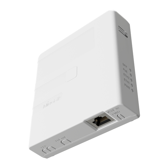
GPEN21
GPEN21
GPEN21 allows powering a PoE capable device over the Ethernet, using the same voltage, as provided with the DC input jack.
Powering
The device accepts power from a direct-input power jack (5.5 mm outside and 2 mm inside, female, pin positive plug) 12-57 V DC.
Max power consumption 50 W.
Power output
The device supports PoE out from the Ethernet port located under the cover. You can power Mikrotik devices that support passive powering through
Ethernet.
GPEN21 has an Ethernet and SFP port for fiber connectivity. Customers can choose to use GPEN21 to power the optical module for uplink to provider, or
to provide PoE
to power Ethernet uplink to the provider (that uses our GPeR and/or netPower products), which cannot be used together.
Mode button
Reserved for future use.
Mounting
Step 1:
1.
Remove the cover screw using a PH2 screwdriver;
2.
Remove the cover to access mounting points.
Step 2:
1.
Drill holes using drill bit;
2.
Insert dowels if needed;
3.
Attach the unit to the wall and secure it with screws.
Advertisement
Table of Contents

Subscribe to Our Youtube Channel
Related Manuals for MikroTik GPEN21


Summary of Contents for MikroTik GPEN21
- Page 1 The device supports PoE out from the Ethernet port located under the cover. You can power Mikrotik devices that support passive powering through Ethernet. GPEN21 has an Ethernet and SFP port for fiber connectivity. Customers can choose to use GPEN21 to power the optical module for uplink to provider, or to provide PoE to power Ethernet uplink to the provider (that uses our GPeR and/or netPower products), which cannot be used together.
- Page 2 Step 1.Step 2. Step 3: Plug in the Ethernet cable going to the unit that will be powered; Plug in the power source for the GPEN. Outgoing Ethernet cable can be guided through position A or B for cable leading into the wall. Step 4: Re-attach cover;...
- Page 3 Useful for RouterBOOT debugging and recovery. Accessories The package includes the following accessories that come with the device: K-62 screw kit includes four screws and dowels for mounting on the wall. Please visit wiki pages for MikroTik SFP module compatibility table: https://wiki.mikrotik.com/wiki/MikroTik_SFP_module_compatibility_table Specifications https://i.mt.lv/cdn/product_files/GPEN_concept_200204.pdf Federal Communication Commission Interference Statement This equipment has been tested and found to comply with the limits for a Class B digital device, pursuant to Part 15 of the FCC Rules.
- Page 4 Информация о дате изготовления устройства указана в конце серийного номера на его наклейке через дробь. Первая цифра означает номер года (последняя цифра года), две последующие означают номер недели. Изготовитель: Mikrotikls SIA, Aizkraukles iela 23, Riga, LV-1006, Латвия, support@mikrotik.com. Сделано в Китае, Латвии или Литве. Cм. на упаковке.
Need help?
Do you have a question about the GPEN21 and is the answer not in the manual?
Questions and answers