Sign In
Upload
Manuals
Brands
Nuvoton Manuals
Motherboard
NuMicro NuMaker-IoT-M467
Nuvoton NuMicro NuMaker-IoT-M467 Manuals
Manuals and User Guides for Nuvoton NuMicro NuMaker-IoT-M467. We have
1
Nuvoton NuMicro NuMaker-IoT-M467 manual available for free PDF download: User Manual
Nuvoton NuMicro NuMaker-IoT-M467 User Manual (58 pages)
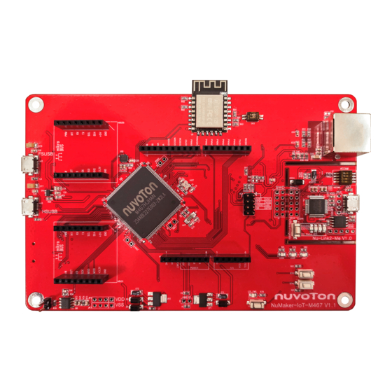
Evaluation Board for NuMicro M460 Series
Brand:
Nuvoton
| Category:
Motherboard
| Size: 5 MB
Table of Contents
Table of Contents
2
Overview
7
Figure 1-1 Numaker-Iot-M467 Evaluation Board
7
Features
8
Introduction to Numicro Iot Platform
9
Hardware Configuration
10
Front View
10
Figure 4-1 Front View of Numaker-Iot-M467
10
Rear View
11
Figure 4-2 Rear View of Numaker-Iot-M467
11
Extension Connectors
12
Arduino uno Compatible Extension Connectors
12
Figure 4-3 Arduino uno Compatible Extension Connectors
12
Table 4-1 Extension Connectors
12
Table 4-2 Arduino uno Extension Connectors and M467HJHAN Mapping GPIO List
13
Mikrobus TM Interface
14
Table 4-3 Mikrobus™ Mapping with M467HJHAN
14
Power Supply Configuration
15
VIN Power Source
15
Power Sources
15
Table 4-4 Vin Power Source
15
Table 4-5 5 V Power Sources
15
Power Sources
16
Power Connectors
16
Table 4-6 3.3 V Power Sources
16
Table 4-7 Power Connectors
16
USB Connectors
17
Power Switches
17
Power Supply Models
17
Figure 4-4 External Power Supply Sources on Nu-Link2-Me
17
Table 4-8 USB Connectors
17
Table 4-9 Power Switches
17
Figure 4-5 External Power Supply Sources on M467 Target Board
18
Table 4-10 Supply External Power through Nu-Link2-Me
18
Figure 4-6 Detach the Nu-Link2-Me from Numaker-Iot-M467
19
Table 4-11 Supply External Power for M467 Target Board
20
External Reference Voltage Connector
21
Ammeter Connector
21
Figure 4-7 Wiring between Ammeter Connector and Ammeter
21
Table 4-12 External Reference Voltage Connector
21
Table 4-13 Ammeter Connector
21
Push Buttons
22
Table 4-14 Push Buttons
22
Leds
23
4.10 Nu-Link2-Me
23
VCOM Switches
23
Table 4-15 Leds
23
Table 4-16 VCOM Function of Nu-Link2-Me
23
Status Leds
24
Table 4-17 Operation Status LED Patterns
24
Quick Start
25
Toolchains Supporting
25
Nuvoton Nu-Link Driver Installation
25
Figure 5-1 Nu-Link USB Driver Installation Setup
25
Figure 5-2 Nu-Link USB Driver Installation
26
BSP Firmware Download
27
Hardware Setup
27
Figure 5-3 Open VCOM Function
27
Figure 5-4 ICE USB Connector
27
Figure 5-5 Device Manger
28
Figure 5-6 Putty Session Setting
28
Find the Example Project
29
Execute the Project under Toolchains
29
Keil MDK
29
Figure 5-7 Template Project Folder Path
29
Figure 5-8 Warning Message of "Device Not Found
29
Figure 5-9 Project File Migrate to Version 5 Format
30
Figure 5-10 Debugger Setting in Options Window
30
Figure 5-11 Programming Setting in Options Window
31
Figure 5-12 Compile and Download the Project
31
Figure 5-13 Keil MDK Debug Mode
32
Figure 5-14 Debug Message on Serial Port Terminal Windows
32
Iar Ewarm
33
Figure 5-15 IAR EWARM Window
33
Figure 5-16 Compile and Download the Project
33
Figure 5-17 IAR EWARM Debug Mode
34
Figure 5-18 Debug Message on Serial Port Terminal Windows
34
Nueclipse
35
Figure 5-19 Import the Project in Nueclipse
35
Figure 5-20 Import Projects Windows
35
Figure 5-21 Open Project Properties Window
36
Figure 5-22 Project Properties Settings
36
Figure 5-23 Build Project
37
Figure 5-24 Open Debug Configuration
37
Figure 5-25 Main Tab Configuration
38
Figure 5-26 Debugger Tab Configuration
38
Figure 5-27 Startup Tab Configuration
39
Figure 5-28 Nueclipse Debug Mode
40
Figure 5-29 Debug Message on Serial Port Terminal Windows
40
Numaker-Iot-M467 Schematics
41
Nu-Link2-Me
41
Figure 6-1 Nu-Link2-Me Circuit
41
M467 Target Board
42
Power Source
42
Figure 6-2 Power Source Circuit
42
M467Hjhan
43
Figure 6-3 M467HJHAN Circuit
43
SPI Flash
44
Figure 6-4 SPI Flash Circuit
44
Full-Speed USB
45
Figure 6-5 Full-Speed USB Circuit
45
High-Speed USB
46
Figure 6-6 High-Speed Circuit
46
Micro SD Card
47
Figure 6-7 Micro SD Card Circuit
47
Arduino uno I/F
48
Figure 6-8 Arduino uno I/F Circuit
48
CAN FD Transceiver
49
Figure 6-9 CAN FD Transceiver Circuit
49
Ethernet PHY
50
Figure 6-10 Ethernet PHY Circuit
50
Thermal Sensor
51
Figure 6-11 Thermal Sensor Circuit
51
Leds & Buttons
52
Figure 6-12 Leds and Buttons Circuit
52
Wi-Fi Module
53
Figure 6-13 Wi-Fi Module Circuit
53
Mikrobus TM Interface
54
Figure 6-14 Mikrobus
54
6-Axis Sensor
55
Figure 6-15 6-Axis Sensor Circuit
55
PCB Placement
56
Figure 6-16 Front Placement
56
Figure 6-17 Rear Placement
56
Revision History
57
Advertisement
Advertisement
Related Products
Nuvoton NuMicro NuMaker-IoT-M487
Nuvoton NuMaker-IoT-M2354U
Nuvoton NuMaker-IoT-M2354C
Nuvoton NuMicro NuMaker-IoT-MA35D1-A1
Nuvoton NuMicro NuMaker-IIoT-NUC980G2D
Nuvoton NuMaker-IoT-MA35D0-A1
Nuvoton NuMicro NuMaker-IIoT-NUC980G1D
Nuvoton NuMaker-IIoT-NUC980G1
Nuvoton NuMaker-LoRaG915
Nuvoton NuMicro NuMaker-M256SD
Nuvoton Categories
Motherboard
Microcontrollers
Computer Hardware
Amplifier
Control Unit
More Nuvoton Manuals
Login
Sign In
OR
Sign in with Facebook
Sign in with Google
Upload manual
Upload from disk
Upload from URL