Table of Contents
Advertisement
Quick Links
INSTRUCTION MANUAL
FOR
AMRON INTERNATIONAL DIVING SUPPLY, INC.
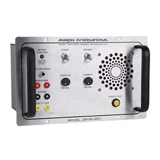
MODEL 2810A-2001
Single Lock Chamber Communicator
S/N
_____________________
This manual and the information contained herein is provided for use as an operation and
maintenance guide. No license or rights to manufacture, reproduce, or sell either the manual or
articles described herein are given. AMRON INTERNATIONAL DIVING SUPPLY, Inc. reserves
the right to change specifications without notice.
Amron International Diving Supply, Inc.
1380 Aspen Way
Vista, California 92081 U.S.A
PHONE (760) 208-6500
FAX (760) 599-3857
Email:
sales@amronintl.com
www.amronintl.com
Copyright © 2005, AMRON INTERNATIONAL, INC.
Revised August 2010
Advertisement
Table of Contents

Subscribe to Our Youtube Channel
Related Manuals for Amron 2810A-2001


Summary of Contents for Amron 2810A-2001
- Page 1 This manual and the information contained herein is provided for use as an operation and maintenance guide. No license or rights to manufacture, reproduce, or sell either the manual or articles described herein are given. AMRON INTERNATIONAL DIVING SUPPLY, Inc. reserves the right to change specifications without notice.
-
Page 2: Table Of Contents
Quick Simulcom Check ....................8.2 Comprehensive 2-Wire and Simulcom Check .............8.3 Problems And Their Possible Causes................8.4 Drawings & Schematics General .........................9.1 Parts Layout 2811B-200 ....................9.2 Parts Layout 2324-202....................9.3 Front Panel 2810A-2001 ....................9.4 Schematic 2810A-2001....................9.5 Parts Identifier- Front Panel Model 2810A-2001............9.6 Mounting Detail Model 2810A-2001................9.7... - Page 3 TABLE OF CONTENTS Parts List General Information ....................10.1 2810A-2001 Chamber Communicator ................10.2 2811B-200 PC Card Assembly ...................10.3 2323-6002 Charger Chassis Assembly...............10.4 2824-202 Power Supply PC Card Assembly ..............10.5 2810A-FS Field Spares Kit..................10.6 2810A-SS Shop Spares Kit..................10.7...
-
Page 4: Specifications
Operational Supply Voltage ........9 Volts Minimum - 18 Volts Maximum Sensitivity (Input)....................... 1 mV Output Power (RMS @ 4 OHM Load, 14 V ) ............ 20 Watts Battery Life, Model 2810A-2001................50 Hours DC Circuit Operating Voltage................12 VDC MECHANICAL Panel ......................Stainless Steel Enclosure ................ -
Page 5: General Information
The AMCOM I has independent volume controls (operator and lock). The 2810A-2001 can be used with a hand held microphone, which incorporates automatic talk back speaker cut out. This feature greatly reduces the amount of background noise, and under noisy... -
Page 6: Options & Accessories
25’ extension on the headset. This is a 2-wire configuration. Custom lengths are available. 2. Model 2822-28 Amron Headset Extension (Simulcom - 4-wire) belt module with 25 feet of 1/4" O.D. cable - allows operator to talk freely on Simulcom while connected to a 25’... -
Page 7: Warranty And Service Policy
INTERNATIONAL DIVING SUPPLY, Inc. literature covering this product, for a period of 90 days from date of shipment. Amron’s obligations under this warranty are limited to the repair of or replacement, at AMRON’S option, of defective materials. This warranty shall not cover defects, which are the result of misuse, negligence, accident, repair or alterations. -
Page 8: Controls And Connections
CONTROLS & CONNECTIONS CONTROLS & CONNECTIONS Before using the AMCOM I series diver communications system, you should familiarize yourself with its operating controls and connections. Improper use of controls and connections will deprive the user of the full benefit of this communication system. Operator Controls POWER Switch - Applies power to the unit. -
Page 9: Operation
Simulcom (4-wire) Operation Connect the cable from the 2810A-2001, red and black dual banana jacks on the rear panel of the communicator to the Chamber Comm. Box Model 3111 or equivalent. Connect a headset (2460- 31R) to the Model 3111. -
Page 10: Theory Of Operation
THEORY OF OPERATION THEORY OF OPERATION Refer to the diagrams and schematics while reading this section. This Section describes the function of the electronic circuits. AMPLIFIER CARD 2811B-200 Signal input U2A and U2B are differential input amplifiers that accept dynamic microphone level signals (1 to 10mv.) and amplify them. -
Page 11: Audio Output Volume Controls
THEORY OF OPERATION AUDIO OUTPUT VOLUME CONTROLS Volume Control The filter output signal is attenuated through operator volume control R101 and chamber volume control R103. This adjusts the signal going to the power amplifier U2 via C9 & C15. 2-Wire Operation Input audio signals from the chamber are amplified and directed to the operator's headset and speaker through relays K2 and K3. -
Page 12: Chamber Radio Field Check Procedures
MAINTENANCE CHAMBER RADIO FIELD CHECK PROCEDURES The following procedures are a step-by-step procedure to do a functional check of your radio, using only a headset. These steps check all communication functions of the radio in both 2-wire and Simulcom modes. This means that if your radio checks with these steps, any communication problems must be somewhere else in the system, such as umbilical connections, speakers, and/or microphones. -
Page 13: Comprehensive 2-Wire And Simulcom Check
MAINTENANCE COMPREHENSIVE 2-WIRE AND SIMULCOM CHECK Set all volume controls at mid-scale; turn power on. Operator circuit check Identify headset microphone lead and headset earphone lead. If required, plug into dual banana jack adapters. (Usually the microphone plug is red.) Plug in headset microphone to Operator’s Microphone (input, red jacks, front panel) and headset earphone to Operator’s Headset (input/output, black jacks, front panel). - Page 14 PROBLEMS AND THEIR POSSIBLE CAUSES General Amron has many units that have been in hard use for over a decade. The primary cause for complete failure of a unit is corrosion from salt water that has been allowed to continuously seep in after a unit is no longer watertight.
- Page 15 MAINTENANCE PROBLEMS AND THEIR POSSIBLE CAUSES Garbled voice to chamber Operator to chamber volume is set too high, reduce volume. Chambers earphones corroded or defective, replace same. Operator's microphone (speaker) defective or full of moisture, empty water out of speaker or replace Operator headset.
-
Page 16: Problems And Their Possible Causes
MAINTENANCE PROBLEMS AND THEIR POSSIBLE CAUSES Chamber hears Operator but Operator cannot hear chamber, or volume is very low, 2-wire Check to see if chamber is connected to microphone and not earphone. Check to see that volume levels are not turned down. Inspect chamber connections. Feedback, Simulcom Operator's speaker on while headset is connected, Unused chamber communications connected to system... - Page 17 11.5 and 12.5 volts. The battery voltage of a discharged battery (rechargeable) is 10.0 volts, the battery should not be operated below this point as permanent damage will occur. Amron communicators use gel-cell type rechargeable batteries.
-
Page 18: Drawings & Schematics
DRAWINGS & SCHEMATICS GENERAL The following drawings illustrate the electrical and mechanical details of the chamber communication unit. The corresponding parts lists for each drawing are detailed in the parts lists section. Revisions As drawings are updated, information about changes is incorporated into a revision sheet. This revision sheet appears in the manual immediately after the drawings. -
Page 19: Parts Layout 2811B-200
DRAWINGS & SCHEMATICS PARTS LAYOUT 2811B-200... -
Page 20: Parts Layout 2324-202
DRAWINGS & SCHEMATICS PARTS LAYOUT 2324-202... -
Page 21: Front Panel 2810A-2001
DRAWINGS & SCHEMATICS FRONT PANEL 2810A-2001... -
Page 22: Schematic 2810A-2001
DRAWINGS & SCHEMATICS SCHEMATIC 2810A-2001... -
Page 23: Parts Identifier- Front Panel Model 2810A-2001
DRAWINGS & SCHEMATICS PARTS IDENTIFIER – FRONT PANEL MODEL 2810A-2001... -
Page 24: Mounting Detail Model 2810A-2001
DRAWINGS & SCHEMATICS MOUNTING DETAIL MODEL 2810A-2001... - Page 25 To Order Replacement Parts Contact: Amron international Diving Supply, Inc. 1380 Aspen Way, Vista, California, 92081 U.S.A. Telephone: (760) 208-6500 Fax: (760) 599-3857 Email: sales@amronintl.com...
- Page 26 N/S ......2-520194-2 ........Slide Term (18/22).032 X .187 N/S ......3500..........Cable Tie ny 3/32in X 3.5in N/S ......2405-28 ..........Microphone push To Talk N/S ......2810A-2001/MANUAL ...... Manual 2810A-2001 N/S ......TAT-1/8..........Heat Shrink Tubing 1/8inblack N/S ......8/18-22 ..........Terminal ring no 8 Stud/18ga.
- Page 27 PARTS LIST 2811B-200 PC CARD ASSEMBLY 10.3 Reference Part Number Description C1 ......21CB068........... Capacitor 68pf 50v Ceramic C2,C9,C15 ....MKS2-334J50........Capacitor .33uf 5% 50v C3,C18...... UVP1C330MDA........ Capacitor 33uf 20% 16v C4,C6,C7,C8 .... MKS2-104K63 ........Capacitor .1uf 10% 63v C12,C14....MKS2-104K63 ........Capacitor .1uf 10% 63v C19,C20....
- Page 28 PARTS LIST 2823-6002 CHARGER CHASSIS ASSEMBLY 10.4 Reference Part Number Description N/S ......2324-202 .......... Battery Charger Pc Card Assy N/S ......2324-022 .......... Chassis External Charger N/S ......6-32X2SSPHP........Screw 6-32 2in S/S Ph Phill N/S ......6ISW..........Washer No 6 Internal Star S/S N/S ......
- Page 29 PARTS LIST C2, C5....... ME208-25V470......... Capacitor 470uf 25v Radial C6, C7....... 2324A-2003 ........Capacitor 4700uf 25v U4 ......597-LM317T ........I.C. Lm317t T1......4-44-6016-4H ........Transformer 220/16v 2810A-FS Field Spares Kit For 2810A AND 2810A-1 10.6 Reference Part Number Description Quantity 1........
Need help?
Do you have a question about the 2810A-2001 and is the answer not in the manual?
Questions and answers