CONTENTS 1. Precaution ..............................1 1.1 Safety Precaution .......................... 1 1.2 Warning ............................1 2. Part Names and Features..........................4 2.1 Model Names of Indoor/Outdoor units ..................4 2.2 Part names of Indoor/Outdoor units ....................5 3. Dimension ..............................15 3.1 Indoor Unit ...........................
Page 3
16. Troubleshooting ............................84 16.1 Indoor Unit Error Display ......................85 16.2 Error Display on Two Way Communication Wired Controller ........... 86 16.3 Outdoor unit error display ......................87 16.4 Diagnosis and Solution ......................91 16.5 Main parts check ........................121 17.
Be caution when unpacking and installing the product. 1. Precaution Sharp edges could cause injury, be especially careful of the case edges and the fins on the 1.1 Safety Precaution condenser and evaporator. For installation, always contact the ...
Page 5
If strange sounds or smoke comes Install the drain hose to ensure that from product, turn the breaker off or water is drained away properly. A bad connection may cause water leakage. disconnect the power supply cable. There is risk of electric shock or fire. ...
Page 6
Do not insert hands or other objects through air inlet or outlet while the product is operated. Do not drink the water drained from the product. Use a firm stool or ladder when cleaning or maintaining the product. Be careful and avoid personal injury.
2. Part Names and Features 2.1 Model Names of Indoor/Outdoor units Outdoor units Series Capacity Indoor units YKKE12BXTMCM-RX, Cassette YKJE12BXTMCM-RX YUKE12BYTMCMO-X, YUJE12BYTMCMO-X; YEKE12BXTMCM-WX, A6 Duct YEJE12BXTMCM-WX YKKE18BXTMCM-RX, Cassette YKJE18BXTMCM-RX YFKE18BXTMCM-RX, YUKE18BYTMCMO-X, Floor Ceiling YFJE18BXTMCM-RX YUJE18BYTMCMO-X; YEKE18BXTMCM-WX, A6 Duct YEJE18BXTMCM-WX YEKE24BXTMCM-WX, A6 Duct YEJE24BXTMCM-WX YKKE24BXTMCM-RX,...
Page 11
2.3 Features 2.3.1 Cassette Units 2.3.1.1 Lower Noise Optimize air channel system design to ensure the maximum quietness and comfort. Noise max down 6dB. 2.3.1.2 Turbo Mode (Optional) Turbo function can boost cooling or heating speed in a short period, and makes the room cool ...
Page 12
2.3.1.6 Build-in Drain Pump The drain pump can lift the condensing water up to 750mm upmost. It’s convenient to install drainage piping under most space condition. 2.3.1.7Terminals For Alarm Lamp and Long-distance On-off Controller Connection Are Standard Reserve terminals for the connection of alarm lamp and long-distance on-off controller, more human control.
Page 13
2.3.2 Ceiling-floor Units 2.3.2.1 Two-way Installation The rounded design of the ceiling and floor type air conditioner allows either ceiling or floor-level installation. Ceiling installation saves room space, while floor installation helps prevent the loss of warm air. 2.3.2.2 Brief Design Brief design that is suitable for any interior will not only give you cooling and heating performance ...
Page 14
2.3.2.7 Outside Water Pump for Optional When Ceiling Installation.
Page 15
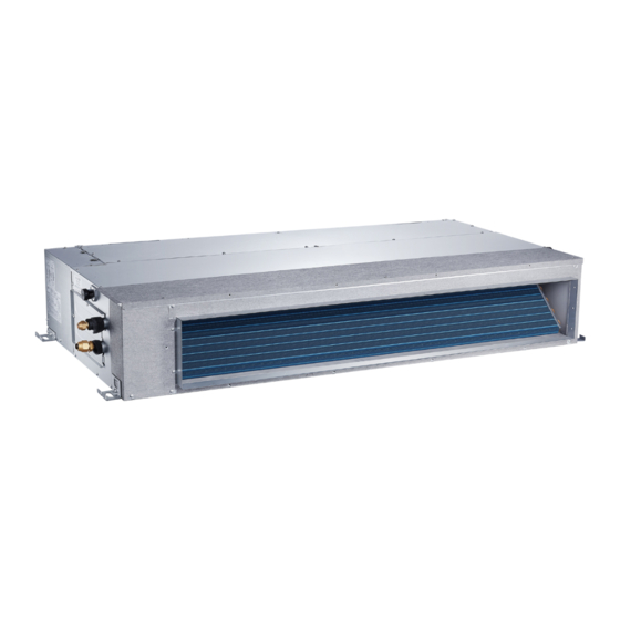
2.3.3 A6 Duct Units Higher Static Pressure 2.3.3.1. As a ducted air conditioner with medium static pressure, it has the widest static pressure range. The maximum static pressure reaches 160Pa Slim Design 2.3.3.2. The industry Lowest height is designed to be fitted into tight roof spaces. *18K unit - 210mm,24K/36K unit - 249mm,48K unit -300mm 2.3.3.3.
Page 16
Air intake from rear (Standard) Air intake from bottom (Optional) 2.3.3.5. Communication wire connection A6 duct uses two wires without polarity connection way, which almost has no mistake during the installation. Easy Clean 2.3.3.6. With a larger window design, once the motor and the blower wheels have been detached, heat exchanger and water receiver tray in behind can be seen very clearly.
Page 17
A ventilation motor (provided by the installer) can be installed inside the fresh air duct to improve the fresh air volume. There are reserved ports for this motor on main PCB (Standard for 3D inverter units, and only optional for DC inverter 53~160 units). 2.3.3.8.Drain pump (Optional) ...
3. Dimension 3.1 Indoor Unit Cassette Units(12K, 18K) Liquid side Gas side Body Drain hole Wiring connection port ( for Service ) E-parts box 4-Screw hole (for install panel) 4-install hanger Drain pipe Fresh air intake Wiring connection port Panel...
Page 19
Cassette Units (24K) 92 92 Fresh air intake 4-install hanger Body Gas side Liquid side Wiring connection port E-parts box Service hole for Test mouth & Test cover draining pump Drain hole 92 92 92 92 Panel Capacity (Btu/h) inch 6.30 2.95 8.07...
Page 20
Ceiling-floor Units Wiring connection port Drain discharge port Fresh air intake Refrigerant pipe hole Hanging arm Capacity (Btu/h) 1068 18K / 24K inch 42.05 26.57 9.25 38.70...
Page 21
A6 Duct Units Model unit (KBtu/h) inch 27.6 19.9 17.7 21.1 23.6 29.2 14.2 inch 34.6 26.5 23.6 27.8 30.8 36.2 20.0 1100 1001 1140 inch 43.3 30.5 27.6 36.5 39.4 44.9 23.5...
3.2 Outdoor Unit Note: The above drawing is only for reference. The appearance of your units may be different. Model unit YUKE12BYTMCMO-X , YUJE12BYTMCMO-X inch 31.5 13.1 21.8 34.3 20.2 13.4 YUKE18BYTMCMO-X , YUJE18BYTMCMO-X inch 33.3 14.3 27.6 36.0 21.3 13.8 1030 YUKE24BYTMCMO-X...
4. Service Space 4.1 Indoor Unit A6 Duct Units Ensure enough space required for installation and maintenance. 200mm(7.87in) or more 300mm(11.81in) or more 600mmx600mm/23.62inx23.62in Check orifice All the indoor units reserve the hole to connect the fresh air pipe. The hole size as following Cassette Units Unit: mm...
4.2 Outdoor Unit (Wall or obstacle) More than 30cm(11.81in) Air inlet More than 60cm More than 30cm (23.62in) (11.81in) Maintain channel More than 60cm Air inlet (23.62in) Air outlet More than 200cm(78.74in)
Page 30
6.1.1 Some connectors introduce: YKKE12BXTMCM-RX,YKJE12BXTMCM-RX, YKKE18BXTMCM-RX,YKJE18BXTMCM-RX A For remote control (ON-OFF) terminal port CN23 and short connector of JR6 1. Remove the short connector of JR6 when you use ON-OFF function; 2. When remote switch off (OPEN), the unit would be off; 3.
Page 31
than 24V, current less than 0.5A 3. When the unit occurs the problem, the relay would be closed, then ALARM works C. For new fresh motor terminal port CN8 1. Connect the fan motor to the port, no need care L/N of the motor; 2.
Page 32
A For remote control (ON-OFF) terminal port CN23 1. Remove the short connector in CN23 when you use ON-OFF function; 2. When remote switch off (OPEN), the unit would be off; 3. When remote switch on (CLOSE), the unit would be on; 4.
Page 33
than 24V, current less than 0.5A 3. When the unit occurs the problem, the relay would be closed, then ALARM works C. For new fresh motor terminal port CN14&CN14 1. Connect the fan motor to the port, no need care L/N of the motor; 2.
Page 34
YEKE12BXTMCM-WX,YEJE12BXTMCM-WX, YEKE18BXTMCM-WX,YEJE18BXTMCM-WX, YEKE24BXTMCM-WX,YEJE24BXTMCM-WX, A. For new fresh motor terminal port (also for Anion generator) CN43: 1. Connect the fan motor to the port, no need care L/N of the motor; 2. The output voltage is the power supply; 3. The fresh motor cannot excess 200W or 1A, follow the smaller one; 4.
Page 35
B For ALARM terminal port CN33 1. Provide the terminal port to connect ALARM, but no voltage of the terminal port, the power from the ALARM system (not from the unit ) 2. Although design voltage can support higher voltage, but we strongly ask you connect the power less than 24V, current less than 0.5A 3.
Page 36
6.1.2 Micro-Switch Introduce: YKKE12BXTMCM-RX,YKJE12BXTMCM-RX, YKKE18BXTMCM-RX,YKJE18BXTMCM-RX, A. Micro-switch SW1 is for selection of indoor fan stop temperature (TEL0) when it is in anti-cold wind action in heating mode. Range: 24 C, 15 C, 8 C, according to EEROM setting (reserved for special customizing). T E L 0 + 1 6 S e tt in g fa n s p e e d T E L 0 + 1 4...
Page 37
Range: Active, inactive D. Micro-switch SW5 is for setting mode priority of multi connection. Range: Heat, cool. E.Micro-switch SW6 is for selection of temperature compensation in heating mode. This helps to reduce the real temperature difference between ceiling and floor so that the unit could run properly. If the height of installation is lower, smaller value could be chosen.
Page 38
YFKE18BXTMCM-RX,YFJE18BXTMCM-RX, YFKE24BXTMCM-RX, YFJE24BXTMCM-RX A. Micro-switch SW1 is for selection of indoor fan stop temperature (TEL0) when it is in anti-cold wind action in heating mode. Range: 24 C, 15 C, 8 C, According to EEROM setting (reserved for special customizing). For YFKE24BXTMCM-RX,YFJE24BXTMCM-RX: S e tt in g fa n s p e e d T E L 0 + 1 6...
Page 39
For YFKE18BXTMCM-RX,YFJE18BXTMCM-RX: S etting fan speed TE L0+23- TE 1 TE L0+21- TE 1 T EL0+18- T E1 TE L0+19- TE 1 T EL0+16- T E1 TE L0+17- TE 1 T EL0+14- T E1 TE L0+15- TE 1 T EL0+12- T E1 T EL0+10- T E1 TE L0+13- TE 1 S uper slow...
Page 40
E.Micro-switch SW6 is for selection of temperature compensation in heating mode. This helps to reduce the real temperature difference between ceiling and floor so that the unit could run properly. If the unit is on-floor installed, 0 should be chosen. Range: 0 C, 2 C, 4...
Page 41
YEKE12BXTMCM-WX,YEJE12BXTMCM-WX, YEKE18BXTMCM-WX,YEJE18BXTMCM-WX, YEKE24BXTMCM-WX,YEJE24BXTMCM-WX A. Micro-switch SW1 is for selection of indoor fan stop temperature (TEL0) when it is in anti-cold wind action in heating mode. Range: 24 C, 15 C, 8 C, according to EEROM setting (reserved for special customizing). S etting fan speed TE L0+23- TE 1 TE L0+21- TE 1...
Page 42
the real temperature difference between ceiling and floor so that the unit could run properly. If the height of installation is lower, smaller value could be chosen. Range: 6 C, 4 C, 2 C, E function (reserved for special customizing) D.
9.2 Outdoor unit Outdoor Unit Microphone 1.0m Note: H= 0.5 × height of outdoor unit Model Noise Level dB(A) YUKE12BYTMCMO-X,YUJE12BYTMCMO-X YUKE18BYTMCMO-X,YUJE18BYTMCMO-X 57.5 YUKE24BYTMCMO-X,YUJE24BYTMCMO-X 58.5...
10 Accessories Duct Units Name Shape Quantity Soundproof / insulation sheath Tubing & Fittings Binding tape Seal sponge Drain joint Drainpipe Fittings (for cooling & heating) Seal ring Wired controller & Its Frame Wired controller Owner's manual Others Installation manual Magnetic ring (twist the electric wires L EMS &...
Page 55
Mounting screw(ST2.9×10-C-H) Remote controller manual Alkaline dry batteries (AM4) Owner's manual Others Installation manual Installation accessory Expansible hook (The product you have Installation hook might not be provided the following accessories Orifice Ceiling-floor Units Name Shape Quantity 1. Remote controller 2.
11. The Specification of Power Type 9K-18K Phase 1-phase 1-phase Power Frequency and Voltage 208-230V, 60Hz 208-230V, 60Hz Circuit Breaker/ Fuse (A) 25/20 25/20 Indoor Unit Power Wiring 3-core cable 3-core cable Outdoor Unit Power Wiring (14AWG) (14AWG) 4-core cable 4-core cable (16AWG) (16AWG)
blockage of the heat exchanger in the 13 Installation Details outdoor unit. If is built over the unit to prevent direct sunlight, rain exposure, direct strong wend, 13.1Location selection snow and other scraps accumulation, make Indoor unit location selection 13.1.1 sure that heat radiation from the condenser ...
Page 59
1. Please refer to the upper data to locate the screw bolts with a block. Position the four positioning screw bolt hole on the ceiling. indoor unit flat using a level indicator to Be sure to mark the areas where ceiling hook prevent leaks.
Page 60
NOTE: 1.Do not put the connecting duct weight on the indoor unit. 13.2.1.6 Fresh air duct installation 2.When connecting duct, use inflammable Dimension : canvas tie-in to prevent vibrating. 3. Insulation foam must be wrapped outside the duct to avoid condensate. An internal duct underlayer can be added to reduce noise, if the end-user requires.
Page 61
13.2.2.3 Install the pendant bolt Select the position of installation hooks according to the hook holes positions showed Adjust the position to ensure the gaps between in upper picture. the body and the four sides of ceiling are even. Drill four holes of Ø12mm, 45~50mm deep at The body's lower part should sink into the the selected positions on the ceiling.
Page 62
Hang the air-in grill to the panel, then connect the lead terminator of the swing motor and that control with corresponding terminators on the body respectively. Note: The panel shall be installed after the wiring connected. Ceiling-floor unit installation 13.2.3 13.2.3.1 Service space for indoor unit 13.2.3.2 Bolt pitch Hang the panel to the hooks on the mainbody.
Page 63
Select the position of installation hooks according to the hook holes positions showed in upper picture. Drill four holes of Ø12mm, 45~50mm deep at the selected positions on the ceiling. Then embed the expansible hooks (fittings). Put the side panels and grilles back. ②...
Page 64
13.2.5.4 Install the main body Make the 4 suspender through the 4 hanger of the main body to suspend it. Adjust the hexangular nuts on the four installation hooks evenly, to ensure the balance of the body. Use a leveling instrument to make sure the levelness of the main body is within ±1°.
Hang the air-in grill to the panel, then connect the lead terminator of the swing motor and that of the control box with corresponding Remove the 4 corner covers. terminators on the body respectively. Install the 4 corner covers back. Hang the panel to the hooks on the mainbody.
Considering the allowable pipe length and height drop to decide the installation position. More than 60cm Make sure the distance and height drop (23.62in) between indoor and outdoor unit not exceeded the date in the following table. Max. Length Max. Elevation Model 9,000Btu/h 82.2...
Page 67
● Decreases in cooling and heating efficiency 1/2" 15.4 15.8 ● Blocks in capillary tubing caused by (12.7) moisture in the refrigerant circuit freezing 5/8" 18.6 19.1 ● Corrosion of parts in the refrigerant system (15.9) caused by water 3/4" (19) 22.9 23.3 The indoor units and the pipes between...
Page 68
more minutes. If the pressure does not the gauge displays a value between 0.3 to 0.5 reach -0.1Mpa(14.5Psi) after 50 minutes Mpa(43.5 to 72.5Psi) has elapsed, check if there are any leaks. 6). Disconnect the charge set and the charging Fully close the Handle Lo valve of the manifold cylinder.
Page 69
hose from the 3-way valve’s service port Use a torque wrench to tighten the 3-way valves immediately and turn off the air conditioner service port cap to a torque of 18N.m. before disconnecting the hose. Be sure to check for gas leaks. 7).
2). To purge the air from the charge hose, open 13.4.6 Re-Installation When the Outdoor Unit Requires Repairs the valve at the bottom of the cylinder and press 1. Evacuation for the whole system the check valve on the charge set (be careful of the liquid refrigerant).
Page 71
Considering the pipeline route and pipe (mm) elevation PVC25 branch Before installing condensate water pipeline, pipe PVC32 determine its route and elevation to avoid PVC40 intersection with other pipelines and ensure PVC50 1440 Could be used slope is straight. PVC63 2760 for confluence...
Page 72
The correct installation will not cause The installation should be considering the converse water flow and the slope of the convenience for future cleaning. branch pipes can be adjusted freely Blowhole The false installation will cause converse Indoor unit Indoor unit water flow and the slope of the branch pipe...
Continuously infusing water until water level alarmed, check whether the drainage pump could discharge water at once. If water level does not decline under warning water level 3 minutes later, it shall cause shutdown of unit. When this situation happens, the normal startup only can be recovered by turning down power supply and eliminating accumulated water.
namely ordinary vacuum drying and special Procedures of special vacuum drying are as vacuum drying. follows: Vacuum drying for 1 hour. Ordinary vacuum drying Vacuum damage, filling nitrogen to reach When conduct first vacuum drying, connect 0.5Kgf/cm2 . pressure gauge to the infusing mouth of Because nitrogen is dry gas, vacuum gas pipe and liquid pipe, and keep vacuum...
Refrigerant may only be charged after The burning performance should over performed the vacuum drying process. 120℃ Always use gloves and glasses to protect According to the local law to choose your hands and eyes during the charge insulation materials work.
Do not use metal wire tube at the place with The temperature of condensate drainage water acid or alkali corrosion, adopt plastic wire is very low. If insulation is not enough, it shall tube to replace it. form dew and cause leakage to damage the ...
Page 77
Whether the drainage is normal. Whether there is vibration or abnormal noise during operation. Outdoor unit Whether there is vibration or abnormal noise during operation. Whether the generated wind, noise, or condensed of by the air conditioner have influenced your neighborhood.
15. Electronic Function 15.1 Abbreviation T1: Indoor room temperature T2: Coil temperature of indoor heat exchanger T3: Coil temperature of condenser T4: Outdoor ambient temperature T5: Compressor discharge temperature 15.3 Main Protection Td: Target temperature 15.3.1 Three minutes delay at restart for compressor 15.2 Display function 1 minute delay for the 1...
If the unit runs in heating mode, the indoor fan For A6 Duct& HESP Duct: will be also controlled by anti-cold wind If a fault occurs on the air volume regulator or function. the regulator enters protection mode, it sends 15.3.7 Compressor preheating functions the error message CF and an instruction to Preheating permitting condition:...
Page 81
(2) Temperature setting function is disabled, T1-Td and no setting temperature is displayed. (3) Indoor fan can be set to high/med/low/auto. 6.0°C(10.8°F) (H-L)*0.75+L (4) The louver operates same as in cooling 5.0°C(9.0°F) (H-L)*0.5+L mode. 4.0°C(7.2°F) (H-L)*0.25+L (5) Auto fan: 2.5°C(4.5°F) 1.0°C(1.8°F) T1-24°C(75.2°F) 15.4.3 Heating Mode...
Page 82
If any one of the following items is satisfied, AC Decrease: Decrease the running frequency to will enter the defrosting mode. the lower level. After the compressor starts up and keeps running, mark the minimum value of T3 from Hold: Keep the current frequency. the 10th minutes to 15th minutes as T30.
Page 83
15.4.6.5 Timer off/on. The machine will turn off results from pressing the FOLLOW ME button automatically when reaching the setting “off” on remote controller or wired remote controller, time, and then turn on automatically when the buzzer will emit a sound and this indicates reaching the setting “on”...
Page 84
forced cooling mode, the pump will start running immediately and continuously, till stop cooling. 2. Once the water level increase and up to the control point, LED will alarm and the drain pump open and continue checking the water level. If the water level fall down and LED disalarmed (drain pump delay close 1 minute) and operate with the last mode.
Page 85
15.4.12 Point check function Press the LED DISPLAY or LED or MUTE button of the remote controller three times, and then press the AIR DIRECTION or SWING button three times in ten seconds, the buzzer will keep ring for two seconds.
Page 86
Enquiry Display value Meaning Remark information T1,T2,T3,T4, -1F,-1E,-1d,-1c,- -25,-24,-23,-22,-21,-2 1. All the displaying temperature is actual T2B,TP,TH, 1b,-1A value. Targeted 2. All the temperature is °C no matter what -19—99 -19—99 Frequency, kind of remote controller is used. A0,A1,…A9 100,101,…109 Actual 3.
16. Troubleshooting Safety Electricity is stored in capacitors, even when the power supply is shut off. Do not forget to discharge the electricity in the capacitors. Electrolytic Capacitors (HIGH VOLTAGE! CAUTION!) For other models, For other models, connect a discharge resistor (approx.100Ω 40W) or a soldering iron plug between the + and - terminals of the electrolytic capacitor on the opposite side of the outdoor printed circuit board (PCB).
16.1 Indoor Unit Error Display Operation Timer lamp Display LED STATUS lamp ☆ 1 time Indoor unit EEPROM parameter error Communication malfunction between indoor and ☆ 2 times outdoor units ☆ 4 times Indoor fan speed malfunction ☆ 5 times Indoor room temperature sensor (T1 ) malfunction ☆...
16.2 Error Display on Two Way Communication Wired Controller Display LED STATUS Communication error between wired controller and indoor unit The cassette faceplate is abnormal Indoor unit EEPROM parameter error Communication malfunction between indoor and outdoor units Indoor fan speed malfunction Indoor room temperature sensor (T1 ) malfunction Evaporator coil temperature sensor (T2) malfunction Refrigerant leakage detection...
16.3 Outdoor unit error display For 9K-24K outdoor unit: LED2 LED1 Problems IU display (Green) (Red) standby for normal Operation normally Compressor drive board EEPROM error ☆ IPM malfunction or IGBT over-strong current protection ☆ Over voltage or too low voltage protection Inverter compressor drive error ☆...
Page 91
For 36K-60K Outdoor Unit Problems Error Code Communication malfunction between indoor and outdoor units Current overload protection Outdoor ambient temperature sensor (T4 ) malfunction Condenser coil temperature sensor (T3) malfunction Compressor discharge temperature sensor (T5) malfunction Outdoor unit EEPROM parameter error Outdoor fan speed malfunction Inverter module (IPM) malfunction Over-voltage or under-voltage protection...
Page 92
will show “-9”.If the temp. is higher than 70 degree, the Outdoor ambient temp.(T4) digital display tube will show “70”. If the indoor unit is not connected, the digital display tube will show: “――” The display value is between 13~129 degree. If the temp. is lower than 13 degree, the digital display tube will show “13”.If the temp.
Page 93
connected, the digital display tube will show: “――” Actual data*HP*10 1# Indoor unit capacity demand code If capacity demand code is higher than 99, the digital display tube will show single digit and tens digit. (For example, the 2# Indoor unit capacity demand code digital display tube show “5.0”,it means the capacity demand is 15.
16.4 Diagnosis and Solution 16.4.1 EEPROM parameter error diagnosis and solution (E0/F4) E0/F4 Error Code Malfunction conditions Indoor or outdoor PCB main chip does not receive feedback from EEPROM chip. Potential causes Installation mistake ● Faulty PCB ● Trouble shooting: Power off, then restart the unit 2 minutes later.
Page 95
16.4.2 Communication malfunction between indoor and outdoor units diagnosis and solution (E1) For 9K-24K: Error Code Malfunction conditions If the indoor unit does not receive feedback from outdoor unit for 110 seconds 4 consecutive times. Potential causes Wiring mistake ● Faulty indoor or outdoor PCB ●...
Page 96
Remark: Use a multimeter to test the DC voltage between 2 port and 3 port of outdoor unit. The red pin of multimeter connects with 2 port while the black pin is for 3 port. When AC is normal running, the voltage will move alternately between -50V to 50V.
Page 97
For 36K-48K: Malfunction Indoor unit does not receive feedback from outdoor unit for 60 conditions seconds OR outdoor unit does not receive feedback from indoor unit for 120 seconds. Possible causes ● Wiring mistakes ● Faulty indoor or outdoor PCB...
Page 98
16.4.3 Fan speed malfunction diagnosis and solution (E3/F5) E3/F5 Error Code Malfunction conditions When indoor fan speed is too low (300RPM) for a certain period of time, the unit ceases operation and the LED displays a failure code. Potential Causes Wiring mistake ●...
Page 99
Index 1: 1. Indoor or outdoor DC fan motor (Control Chip is in Fan Motor) Turn power on and while the unit is on standby, measure the voltage between pin1 and pin3 as well as between pin4 and pin3 in fan motor connector. If the value of the voltage is not within the range shown in the following table, the PCB may be experiencing problems and need to be replaced.
Page 100
16.4.4 Open or short circuit of temperature sensor diagnosis and solution (E4/E5/F1/F2/F3) Error Code E4/E5/F1/F2/F3 Malfunction conditions If the sampling voltage is lower than 0.06V or higher than 4.94V, the LED displays a failure. Potential causes Wiring mistake ● Faulty sensor ●...
Page 101
16.4.5 Refrigerant Leakage Detection diagnosis and solution (EC) Error Code Malfunction conditions Define the evaporator coil temperature T2 of the compressor starts running as Tcool. If the following occurs 3 times, the display shows "EC" and the unit switches off: In the first 8 minutes after the compressor starts up, if T2 <...
Page 102
Water-level alarm malfunction 16.4.6 diagnosis and solution Error Code Malfunction conditions If the sampling voltage is not 5V, the LED will display the failure code. Possible causes ● Wiring mistakes ● Faulty water-level switch ● Faulty water pump ● Faulty indoor PCB...
Page 103
16.4.7 IPM malfunction or IGBT over-strong current protection diagnosis and solution (P0) Error Code Malfunction When the voltage signal the IPM sends to the compressor drive conditions chip is abnormal, the display LED shows “P0” and the AC turn Possible causes Wiring mistake ●...
Page 106
16.4.8 Over-voltage or under-voltage protection diagnosis and solution (P1) Error Code Malfunction conditions Abnormal increases or decreases in voltage are detected by checking the specified voltage detection circuit. Potential causes Power supply issues ● System leakage or blockage ● Faulty PCB ●...
Page 107
16.4.9 High temperature protection of compressor top diagnosis and solution (P2) Error Code Malfunction decision If the sampling voltage is not 5V, the LED will display the failure. conditions Power supply problems. ● Supposed causes System leakage or block ● PCB faulty ●...
Page 108
High temperature protection of IPM board diagnosis and solution (P2)
Page 109
16.4.10 Inverter compressor drive error diagnosis and solution(P4) Error Code Malfunction conditions Abnormalities in the inverter compressor drive is detected by a special detection circuit, which can perform communication signal detection, voltage detection, and compressor rotation speed signal detection. Potential causes Wiring mistake ●...
Page 110
16.4.11 Outdoor IPM module temperature sensor malfunction diagnosis and solution (P7) Error Code Malfunction conditions If the sampling voltage is lower than 0.06V or higher than 4.94V, the LED displays a failure. Potential causes Wiring mistake ● Faulty sensor ● Faulty PCB Trouble shooting:...
Page 111
16.4.12. J0 Malfunction Malfunction conditions When evaporator coil temperature is more than 60°C, the unit stops. It starts again only when the evaporator coil temperature is less than 54°C Possible causes Faulty evaporator coil temperature sensor Dirty heat exchanger ...
Page 112
16.4.13. J1 Malfunction Malfunction conditions When the outdoor pipe temperature is more than 65°C, the unit stops. It starts again only when the outdoor pipe temperature is less than 52°C. Possible causes ● Faulty condenser temperature sensor ● Dirty heat exchanger ●...
Page 113
16.4.14. J2 Malfunction Malfunction conditions When the compressor discharge temperature (T5) is more than 115℃ for 10 seconds, the compressor will stop and not restart until T5 is less than 90℃. Possible causes ● Refrigerant leakage ● Wiring mistake ● Faulty discharge temperature sensor ●...
Page 114
16.4.15. J3 Malfunction Malfunction decision conditions When the voltage signal that IPM send to compressor drive chip is abnormal, the display LED will show “J3” and AC will turn off. Supposed causes ● Wiring mistake ● Faulty IPM board ● Faulty outdoor fan ass’y ●...
Page 116
16.4.17. J5 Malfunction Malfunction conditions If the sampling voltage is not 5V, the LED displays a failure code. Possible causes Wiring mistakes ● Faulty overload protector ● System blockages ● Faulty outdoor PCB ●...
Page 117
16.4.18. J6/P6 Malfunction Malfunction conditions If the sampling voltage is not 5V, the LED displays a failure code. Possible causes ● Wiring mistake Faulty over load protector ● ● System blockages Faulty outdoor PCB ●...
Page 118
16.4.19. J8 malfunction Malfunction decision An abnormal voltage rise or drop is detected by checking the specified conditions voltage detection circuit. Supposed causes Abnormal power supply Wiring mistake Faulty bridge rectifier Faulty IPM board...
Page 120
16.4.20 Communication Malfunction between Indoor Unit and auto-lifting Panel (F7) Indoor PCB does not get the feedback from the PCB of auto Malfunction decision conditions lifting-panel ● Wiring mistake between indoor PCB and auto-lifting panel Possible causes ● Faulty PCB of auto-lifting panel ●...
Page 121
16.4.21 Auto-lifting panel malfunction(F8) Indoor PCB does not get the right close position from the Malfunction decision conditions PCB of auto lifting-panel when the panel motor stops ● Wiring mistake between indoor PCB and auto-lifting panel Possible causes ● Faulty PCB of auto-lifting panel ●...
Page 122
16.4.22 Overcurrent Protection (F0) If the outdoor current exceeds the current limit value, the LED Malfunction decision conditions displays a failure code. ● Wiring mistakes ● Faulty bridge rectifier Possible causes ● System blockages ● Faulty outdoor PCB...
Page 123
Current protection of compressor Was the protection activated in standby? Is the power voltage is Restart the unit when the power normal? supply returns to normal Is outdoor terminal voltage Is the power wiring Reconnect the normal ? wired correctly? power wiring Is the voltage between L and Are L and N wired...
16.5 Main parts check 1. Temperature sensor checking Disconnect the temperature sensor from PCB, measure the resistance value with a tester. Temperature Sensors. Room temp.(T1) sensor, Indoor coil temp.(T2) sensor, Outdoor coil temp.(T3) sensor, Outdoor ambient temp.(T4) sensor, Compressor discharge temp.(T5) sensor. Measure the resistance value of each winding by using the multi-meter.
Page 125
Appendix 1 Temperature Sensor Resistance Value Table for T1,T2,T3,T4 (℃--K) K Ohm K Ohm K Ohm K Ohm ℃ ℉ ℃ ℉ ℃ ℉ ℃ ℉ 115.266 12.6431 2.35774 0.62973 108.146 12.0561 2.27249 0.61148 101.517 11.5 2.19073 0.59386 96.3423 10.9731 2.11241 0.57683 89.5865...
Page 126
Appendix 2 Temperature Sensor Resistance Value Table for T5,TH (℃--K) K Ohm K Ohm K Ohm K Ohm ℃ ℉ ℃ ℉ ℃ ℉ ℃ ℉ 542.7 68.66 13.59 3.702 511.9 65.62 13.11 3.595 62.73 12.65 3.492 455.9 59.98 12.21 3.392 430.5 57.37...
Page 128
2. Compressor checking Measure the resistance value of each winding by using the tester. Position Resistance Value ATF310D43UMT ATQ420D1UMU ATM115D43UFZ2 ASN98D22UFZ ASM135D23UFZ ATF235D22UMT ATF250D22UMT Blue - Blue - 1.57Ω 1.75 Ω 0.75 Ω 0.75 Ω 0.65 Ω 0.38Ω 1.87Ω Black Red - Blue...
Page 129
3. IPM continuity check Turn off the power, let the large capacity electrolytic capacitors discharge completely, and dismount the IPM. Use a digital tester to measure the resistance between P and UVWN; UVW and N. Digital tester Normal resistance value Digital tester Normal resistance value (+)Red...
Page 152
7.2 Heating YEKE12BZTMCMOWX [SI_Unit] HEATING PERFORMANCE AT INDOOR DRY BULB TEMPERATURE TC:TOTAL CAPACITY IN KILOWATTS PI:TOTAL POWER IN KILOWATTS INDOOR OUTDOOR AIRFLOW (CMH) Indoor Conditions (DB ℃ ) Indoor Conditions (DB ℃) DB(℃) 16.0 20.0 22.0 24.0 16.0 20.0 22.0 24.0 -15.0 2.43...
Page 153
YEKE18BZTMCMOWX [SI_Unit] HEATING PERFORMANCE AT INDOOR DRY BULB TEMPERATURE TC:TOTAL CAPACITY IN KILOWATTS PI:TOTAL POWER IN KILOWATTS INDOOR OUTDOOR AIRFLOW (CMH) Indoor Conditions (DB ℃ ) Indoor Conditions (DB ℃) DB(℃) 16.0 20.0 22.0 24.0 16.0 20.0 22.0 24.0 -15.0 3.55 3.53 3.50...
Page 154
YEKE24BZTMCMOWX [SI_Unit] HEATING PERFORMANCE AT INDOOR DRY BULB TEMPERATURE TC:TOTAL CAPACITY IN KILOWATTS PI:TOTAL POWER IN KILOWATTS INDOOR OUTDOOR AIRFLOW (CMH) Indoor Conditions (DB ℃ ) Indoor Conditions (DB ℃) DB(℃) 16.0 20.0 22.0 24.0 16.0 20.0 22.0 24.0 -15.0 4.82 4.77 4.74...
Page 155
YFKE18BZTMCMORX [SI_Unit] HEATING PERFORMANCE AT INDOOR DRY BULB TEMPERATURE TC:TOTAL CAPACITY IN KILOWATTS PI:TOTAL POWER IN KILOWATTS INDOOR OUTDOOR AIRFLOW (CMH) Indoor Conditions (DB ℃ ) Indoor Conditions (DB ℃) DB(℃) 16.0 20.0 22.0 24.0 16.0 20.0 22.0 24.0 -15.0 3.81 3.76 3.74...
Page 156
YFKE24BZTMCMORX [SI_Unit] HEATING PERFORMANCE AT INDOOR DRY BULB TEMPERATURE TC:TOTAL CAPACITY IN KILOWATTS PI:TOTAL POWER IN KILOWATTS INDOOR OUTDOOR AIRFLOW (CMH) Indoor Conditions (DB ℃ ) Indoor Conditions (DB ℃) DB(℃) 16.0 20.0 22.0 24.0 16.0 20.0 22.0 24.0 -15.0 5.11 5.06 5.04...
Page 157
YEKE12BZTMCMORX [SI_Unit] HEATING PERFORMANCE AT INDOOR DRY BULB TEMPERATURE TC:TOTAL CAPACITY IN KILOWATTS PI:TOTAL POWER IN KILOWATTS INDOOR OUTDOOR AIRFLOW (CMH) Indoor Conditions (DB ℃ ) Indoor Conditions (DB ℃) DB(℃) 16.0 20.0 22.0 24.0 16.0 20.0 22.0 24.0 -15.0 2.12 2.09 2.09...
Page 158
YKKE18BZTMCMORX [SI_Unit] HEATING PERFORMANCE AT INDOOR DRY BULB TEMPERATURE TC:TOTAL CAPACITY IN KILOWATTS PI:TOTAL POWER IN KILOWATTS INDOOR OUTDOOR AIRFLOW (CMH) Indoor Conditions (DB ℃ ) Indoor Conditions (DB ℃) DB(℃) 16.0 20.0 22.0 24.0 16.0 20.0 22.0 24.0 -15.0 3.38 3.33 3.33...
Page 159
YKKE24BZTMCMORX [SI_Unit] HEATING PERFORMANCE AT INDOOR DRY BULB TEMPERATURE TC:TOTAL CAPACITY IN KILOWATTS PI:TOTAL POWER IN KILOWATTS INDOOR OUTDOOR AIRFLOW (CMH) Indoor Conditions (DB ℃ ) Indoor Conditions (DB ℃) DB(℃) 16.0 20.0 22.0 24.0 16.0 20.0 22.0 24.0 -15.0 4.33 4.28 4.26...
Page 160
2019 Johnson Controls, Inc. www.johnsoncontrols.com Form: MYHFEC7AMTOR3-190325 Johnson Controls reserve the right to change product features without prior notice.
Need help?
Do you have a question about the HP Series and is the answer not in the manual?
Questions and answers