Table of Contents
Advertisement
INSTALLATION INSTRUCTION
GENERAL
This instruction covers the installation of the following outdoor
units:
The outdoor units are designed to be connected to a matching
evaporator with sweat connect lines and are factory charged
with refrigerant for a matching evaporator plus 15 feet of field
supplied lines.
Matching evaporators contain an orifice liquid feed sized for the
most common usage. The orifice size and/or refrigerant charge
may need to be changed for some indoor-outdoor unit combi-
nations, elevation differences or total line lengths.
INSPECTION
As soon as a unit is received, it should be inspected for possible
damage during transit. If damage is evident, the extent of the
damage should be noted on the carrier's delivery receipt. A
separate request for inspection by the carrier's agent should
be made in writing. See Local Distributor for more information.
REFERENCE
Use this instruction in conjunction with the instruction for the
appropriate indoor unit, air moving system and accessories.
Installer should pay particular attention to the words:NOTE,
CAUTION and WARNING.
NOTES are intended to clarify or make the installation easier.
CAUTIONS identifies procedure which, if not followed carefully,
could result in personal injury, property damage or product
damage.
®
Supersedes: 550.36-N2Y (894)
MODELS H2DH024 thru H2DH060
H2DH024S06
H2DH030S06
H2DH036S06
H2DH042S06
H2DH048S06
H2DH060S06
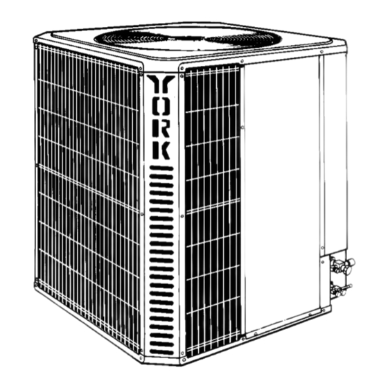
CONDENSING UNITS
SPLIT-SYSTEM COOLING
2 TO 5 TONS
WARNINGS are given to alert the installer that personal injury
and/or equipment damage may result if installation procedures
are not handled properly.
NOMENCLATURE
Product Category
H = Condensing Unit
Product Generation
1,2 = Design Level
Product Identifier
DH = 12.00 SEER Condensing Unit
Nominal Cooling Capacity
024=24,000 BTUH
030=30,000 BTUH
036=36,000 BTUH
Refrigerant Line Connections
S = Sweat-Connect
Voltage Code
06 = 208/230-1-60
LIMITATIONS
The unit should be installed in accordance with all national and
local safety codes.
Limitations for the indoor unit, coil and appropriate accessories
must also be observed. For piping limitations and additional
requirements refer to piping guide 690.01-AD1Y.
The outdoor unit must not be installed with any ductwork in the
air stream. The outdoor fan is the propeller type and is not
designed to operate against any additional external static pres-
sure.
The unit should not be operated at temperatures below 45°F.
LOCATION
Before starting the installation, select and check the suitability
of the location for both the indoor and outdoor unit. Observe all
limitations and clearance requirements, see Figure 1.
The outdoor unit must have sufficient clearance for air entrance
to the condenser coil, for air discharge and for service access.
NOTE: For multiple unit installations, units must be spaced a
minimum of 18 inches apart (coil face to coil face).
If the unit is to be installed on a hot sun exposed roof or a
black-topped ground area, the unit should be raised sufficiently
550.36-N2Y (595)
035- 13122
1 DH
H
024 S 06
042=42,000 BTUH
048=48,000 BTUH
060=60,000 BTUH
Advertisement
Table of Contents

Related Manuals for York H2DH024S06


Summary of Contents for York H2DH024S06
-
Page 1: Condensing Units
Nominal Cooling Capacity 024=24,000 BTUH 042=42,000 BTUH This instruction covers the installation of the following outdoor 030=30,000 BTUH 048=48,000 BTUH units: 036=36,000 BTUH 060=60,000 BTUH H2DH024S06 Refrigerant Line Connections H2DH030S06 H2DH036S06 S = Sweat-Connect H2DH042S06 H2DH048S06 Voltage Code H2DH060S06 06 = 208/230-1-60... - Page 2 550.36-N2Y above the roof or ground to avoid taking the accumulated layer When installing units on a roof, the structure must be capable of hot air into the outdoor unit. of supporting the total weight of the unit, including a pad, lintels, rails, etc., which should be used to minimize the transmission Provide an adequate structural support.
-
Page 3: Installation Procedures
550.36-N2Y INSTALLATION PROCEDURES ORIFICE SELECTION NOTE: The proper orifice must be installed in the evaporator The following sequence of installation steps is suggested. coil liquid connection prior to the connection of the 1. Inspect unit and set in place. refrigerant lines. 2. -
Page 4: System Connections
550.36-N2Y problems. Using too small a line will result in loss of capacity Do not install a filter drier since one is factory installed in every and other problems caused by insufficient refrigerant flow. outdoor unit. Slope horizontal vapor lines at least 1" every 20 feet toward the Insulate all vapor lines with a minimum 1/2"... -
Page 5: Room Thermostat
550.36-N2Y 2. Braze the liquid line to the liquid fitting at the outdoor unit. Be sure to wrap the fitting body with a wet rag. Allow the nitrogen to continue flowing. 3. Carefully remove the rubber plugs from the evaporator liquid and vapor connections. - Page 6 550.36-N2Y To eliminate erratic operation, seal the hole in the wall at the Evacuate the system down to at least 1,000 microns. thermostat with permagum or equivalent to prevent air drafts affecting the anticipators in the thermostat. To verify if the system has no leaks, simply close the valve to the vacuum pump suction to isolate the pump and hold the Route the control wiring into the outdoor unit through the hole system under vacuum.
-
Page 7: System Charge
550.36-N2Y SYSTEM CHARGE Measurement Method The factory charge in the outdoor unit is listed in Table 2 and If a calibrated charging cylinder or accurate weighing device is includes enough charge for the unit and a most sold matched available, add refrigerant accordingly. evaporator. - Page 8 550.36-N2Y TABLE 4 - Superheat Value OUTDOOR DB°F INDOOR WB °F* 100 105 110 115 *Evaporator Entering Air °F TABLE 5 - Temperature and Pressure SUCTION SUCTION SERVICE VALVE SUPERHEAT PRESSURE PSIG (Service Port) 61.5 64.2 67.1 70.0 73.0 76.0 79.2 82.4 ** Saturation Temperature...
-
Page 9: Electrical Connections
550.36-N2Y ELECTRICAL CONNECTIONS should be energized for at least 8 hours before the thermostat is set to operate the compressor. 1. Check the electrical supply to be sure that it meets the values specified on the unit nameplate and wiring label. CAUTION: An attempt to start the compressor without at least 8 hours of crankcase heat will damage the com- 2. - Page 10 550.36-N2Y EXAMPLE: H2DH024 unit with a 78 PSIG measured suc- EXAMPLE: H2DH036 unit with a 76 PSIG measured suc- tion pressure at 95°O.D. ambient-liquid line pressure tion pressure at 95°O.D. ambient-liquid line pressure should be approximately 220 PSIG. should be approximately 220 PSIG. LIQUID PRESSURE (PSIG) LIQUID PRESSURE (PSIG) 024,...
-
Page 11: Instructing The Owner
550.36-N2Y A “higher” than normal liquid pressure may point out a dirty 2. The indoor blower (furnace or air handler) will be operating, discharging cool air from the ducts. condenser coil, or non-condensibles in the system (not evacu- ated properly) or a condenser fan motor not running at full 3. - Page 12 Unitary Products Group P.O. Box 1592, York, Pennsylvania USA 17405-1592 Subject to change without notice. Printed in U.S.A. 550.36-N2Y Copyright © by York International Corporation 1995. All Rights Reserved. Code: SBY RPC 8M 695 .66...
Need help?
Do you have a question about the H2DH024S06 and is the answer not in the manual?
Questions and answers