Table of Contents
Advertisement
Installation
and
Maintenance
Manual
INVERTER-DRIVEN
MULTI-SPLIT SYSTEM
HEAT PUMP
AIR CONDITIONERS
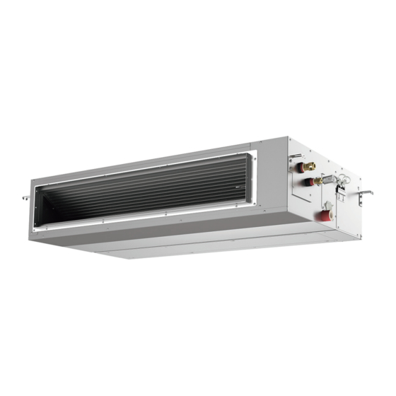
Type
Ducted
(H,Y)IDH072B21S
(High Static)
(H,Y)IDH096B21S
IMPORTANT:
READ AND UNDERSTAND
THIS MANUAL BEFORE
INSTALLING THIS HEAT
PUMP AIR CONDITIONER.
KEEP THIS MANUAL FOR
FUTURE REFERENCE.
Model
P01432Q
Advertisement
Table of Contents

Related Manuals for York IDH072B21S Series


Summary of Contents for York IDH072B21S Series
- Page 1 Installation Maintenance Manual INVERTER-DRIVEN MULTI-SPLIT SYSTEM HEAT PUMP AIR CONDITIONERS Type Model Ducted (H,Y)IDH072B21S (High Static) (H,Y)IDH096B21S IMPORTANT: READ AND UNDERSTAND THIS MANUAL BEFORE INSTALLING THIS HEAT PUMP AIR CONDITIONER. KEEP THIS MANUAL FOR FUTURE REFERENCE. P01432Q...
- Page 2 ATTENTION Each model number and all matching model numbers within a system must have the same version of software. Follow these steps to verify that your product model numbers have the same version of software. • Access the main printed circuit board in each product. •...
- Page 3 Important Notice ● Johnson Controls Inc. pursues a policy of continuing improvement in design and performance in its products. As such, Johnson Controls Inc. reserves the right to make changes at any time without prior notice. ● Johnson Controls Inc. cannot anticipate every possible circumstance that might involve a potential hazard. ●...
-
Page 4: Table Of Contents
TABLE OF CONTENTS 1. Introduction ..............................1 2. Safety Instructions ............................1 3. Before Installation ............................7 3.1 Combination of Outdoor Unit and Indoor Unit ..................7 3.2 Transportation and Handling ........................7 3.3 Factory-Supplied Accessories ........................8 3.4 Necessary Tools and Instrument List for Installation ................8 4. -
Page 5: Introduction
Introduction Read following sections carefully before installing this product. Read over the "Installation and Maintenance Manual" for the outdoor unit as well. Provide this information and the warranty must be provided to all installers and users. Ask end users to maintain copies for future reference. (Refrigerant Piping Work) (Electrical Wiring Work) (Ref. - Page 6 ● Do not touch or adjust any safety devices inside the indoor or outdoor units. All safety features, disengagement, and interlocks must be in place and functioning correctly before the equipment is put into operation. If these devices are improperly adjusted or tampered with in any way, a serious accident can occur.
- Page 7 Installation Precautions To reduce the risk of serious injury or death, the following installation precautions must be followed. ● When installing the unit into… ◦ A wall: Make sure the wall is strong enough to hold the unit’s weight. It may be necessary to construct a strong wood or metal frame to provide added support.
- Page 8 Refrigerant Precautions To reduce the risk of serious injury or death, the following refrigerant precautions must be followed. ● As originally manufactured, this unit contains refrigerant installed by Johnson Controls. Johnson Controls uses only refrigerants that have been approved for use in the unit’s intended home country or market.
- Page 9 Electrical Precautions Take the following precautions to reduce the risk of electric shock, fire or explosion resulting in serious injury or death. ● Highly dangerous electrical voltages are used in this system. Carefully refer to the wiring diagram and these instructions when wiring. Improper connections and inadequate grounding can cause serious injury or death.
- Page 10 ● Proper handling of this unit requires two-people. Safe handling and installing the indoor unit requires the strength of two people. Mounting the unit alone may cause injury due to fall of the unit. Although the unit may be girded with steel banding, do not use it for transportation. Avoid contact with finned surfaces of the heat exchanger as sharp edges can cause severe injury to hands and fingers.
-
Page 11: Before Installation
Before Installation Combination of Outdoor Unit and Indoor Unit The combination capacity of indoor unit against the outdoor unit is selected depending on the outdoor unit capacity. Refer to “Installation and Maintenance Manual” for outdoor unit to decide the required combination of indoor and outdoor units, and the combination unit capacity. -
Page 12: Factory-Supplied Accessories
Factory-Supplied Accessories Check to ensure that the following accessories are packed with the indoor unit. The screws, washers and flare nuts are packed in the pipe insulation. Accessory Qty. Purpose Washer (M10) For Unit Suspension Hose Clamp For Condensate Pipe Connection Pipe Insulation For Refrigerant Liquid Piping Connection ID 1 inch (26mm) -
Page 13: Installation Location
Installation Location (1) Install the indoor unit, allowing for proper clearance for operation and maintenance access, as shown in Figure 4.1. Unit: inch [mm] Electrical Control Box 5-7/8 to 7-7/8 [150 to 200] Service Space of False Ceiling for Cleaning the Heat Exchanger Service Access Panel Figure 4.1 Operation and Installation Space (2) Consider the air distribution from the indoor unit to the space of the room, and select a suitable location... -
Page 14: Suspension Bolts And Piping Connections
Suspension Bolts and Piping Connections (1) Mark the positions of the suspension bolts, refrigerant pipe connections and condensate pipe connection. (2) Installation dimensions are shown in Figure 5.2. Unit: inch [mm] 52-3/8 [1330] (for Suspension Bolt) 49-3/16 [1250] 1-9/16 [40] 39-3/8 [1000] 5-7/16 [138]... -
Page 15: Adjusting Of Unit Level
(1) Prepare the suspension bolts, washers, nuts Retaining Nut and vibration-proof rubbers, as shown in Figure 5.4. Washer Vibration-proof Rubber Indoor Unit Vibration-proof Rubber Washer Figure 5.4 Suspension Bolts and Nuts (2) Suspension Indoor Unit * Hook the suspension bracket to the nut, washer and vibration-proof rubber of each suspension bolt, as shown, starting at the opposite side and working over to the service cover side. -
Page 16: Connecting Supply Duct
Connecting Supply Duct (1) The supply duct should be connected with the indoor unit through canvas ducts, in order to avoid abnormal sound vibration (Refer to Figure 5.7). The unit is equipped with a pre-drilled duct flange for the return and supply duct connection. (2) Duct material should be non-flammable material. -
Page 17: Installation Of Auxiliary Heater (Field-Supplied)
Installation of Auxiliary Heater (Field-Supplied) ● When the auxiliary heater shall be installed and connected, make selection by following local codes, regulations and approved by UL1996, and refer to this manual. Improper installation may result in fire from overheating. ● When the auxiliary heater shall be installed and connected, do not install in places where heater can come into contact with combustible materials. Otherwise, fire may result. ● Provide adequate clearance spacing between the auxiliary heater and indoor unit. Refer to the auxiliary heater manual for details. Otherwise, fire may result from over heating the indoor unit. ● Do not attach the auxiliary heater directly to the indoor unit. Otherwise, fire may result from combustible materials inside the indoor unit. ● Route the auxiliary heater wiring so that it can not come into contact with any part of the heater. Otherwise, fire may result. ● When the auxiliary heater shall be installed and connected, duct material should be a sheet metal or non-flammable material. Otherwise, fire may result. ● Fire may result from debris and dust inside the duct. Indoor unit must be cleaned on a regular basis by following the Service Manual. Also auxiliary heater and duct must be cleaned on a regular basis by following their manuals. ● Auxiliary heater must be properly selected so that double overheating safety protection devices (Thermal Protector and Thermal Fuse) are built-in. Otherwise, fire may result from over heating of heater when the components such as relays fails. P01432Q-rev.1... -
Page 18: Selection Of Auxiliary Heater
5.7.1 Selection of Auxiliary Heater Auxiliary heater for connection can only be duct heater type. When using the auxiliary heater, auxiliary heater capacity must be properly selected. Otherwise, fire may result from abnormal heating of heater. Select the allowable auxiliary heater capacity by following the procedure below. -
Page 19: Auxiliary Heater Connection
5.7.2 Auxiliary Heater Connection When the auxiliary heater shall be used, wire the circuit as shown below. Example of Electrical Wiring Relay and 3 Pin Connector Kit Connector Cable Indoor Unit (PSC-5RA) (PCC-CN1925-H) PCB1 CN1925 PCB1: Pins 3 and 4 of CN1925 Unit Side (Responsible) Wired Controller Field Installation Side (Out of Responsibility) -
Page 20: Refrigerant Piping Work
6. Refrigerant Piping Work Use the specified non-flammable refrigerant (R410A) to the outdoor unit in the refrigerant cycle. Do not charge the unit with materials other than R410A, such as hydrocarbon refrigerants (propane and isobutan), oxygen, flammable gases (acetylene, ammonia, etc.) or poisonous gases when installing, maintaining and moving the unit. These flammables are extremely dangerous and may cause explosion, a fire, or injury. For details on refrigerant piping work, vacuum pump, and refrigerant charge, refer to the "Installation and Maintenance Manual" for the outdoor unit. Piping Materials (1) The tolerance of refrigerant piping length differs depending on the combination with the outdoor unit. Refer to “Installation and Maintenance Manual”... -
Page 21: Piping Connection
Piping Connection (1) Position of piping connection is shown below. Unit: inch [mm] Refrigerant Liquid Pipe Connection Refrigerant Gas Pipe Connection 2-7/8 [72] (Condensate Pipe Connection) 9-15/16 [252] 4-15/16 [126] (Refrigerant Gas and Liquid Pipe Connection) 13-5/8 [346] 18-7/16 [469] Condensate Pipe Connection VP25 (Outer Diameter φ1-1/4 [32]) ● Cut the pipe end before brazing to remove the cap, and discharge gas inside the pipe. - Page 22 (3) After brazing, insulate the pipes after checking that there is no leakage. At that time, be sure to cover the space between two insulating piece by insulation pipe (factory-supplied accessory). Thermal Insulation Pipe Thermal Insulation (Accessory) Pull Liquid Pipe Indoor Unit Gas Pipe Thermal Insulation...
-
Page 23: Condensate Piping
Condensate Piping Do not put the condensate pipe for the indoor unit into the drainage trench where corrosive gases occur. Otherwise, poisonous gases flow into the room, which may cause poisoning. NOTICE ● Ensure that the condensate pipe discharges water properly. If connected incorrectly, it may cause leaks leading to property damage. ● Do not provide an upward slope or a rising part for the condensate pipe. Otherwise, the condensate water will flow back into the unit and it may cause the water leakage when the unit operation is stopped. - Page 24 NOTICE After performing condensate piping work and electrical wiring, verify that water flows smoothly as in the following procedure. Checking with the Float Switch a. Turn ON the power supply. b. Pour 68 to 84oz (2 to 2.5 liters) of water into the condensate pan. c.
-
Page 25: Electrical Wiring
Electrical Wiring ● All electrical work must be done as outlined in this manual and in accordance with this manual. Substandard work can result in fire and damage to the unit. ● Use specified cables between units and choose the cables correctly. If not, an electrical shock or fire may occur. ● Do not open the service cover or access panel for the indoor or outdoor units without turning OFF the main power supply. It can result in an electrical shock. ● Turn OFF the main power switch of the indoor unit and the outdoor unit before attempting any electrical wiring work or a periodical check is performed. If not, it will result in an electric shock or a fire. ● Check to ensure that the indoor fan and the outdoor fan have stopped before attempting any electrical wiring work or for any scheduled electrical work that is being performed. ● Tighten screws according to the following torque. M3.5: 0.9 ft·lbs (1.2 N·m) M5: 1.5 to 1.8 ft·lbs (2.0 to 2.4 N·m) ● Secure all cables together with cable bands and seal the connecting hole against moisture and insects. ● Run the electrical wiring through the connecting hole in the side cover when using conduit. ● Secure the wired controller cable using the cable band inside the electrical box. General Check (1) Make sure that the field-selected electrical components: (main power switches, circuit breakers, wires, conduit connectors, and wire terminals) have been properly labeled in accordance with electrical data as specified in the Engineering Manual. -
Page 26: Electrical Wiring Capacity
Electrical Wiring Capacity 8.2.1 Field Minimum Wire Sizes for Power Supply • This equipment can be installed with a GFCI, which is a recognized measure for added protection to a properly grounded unit. Install appropriate sized breakers / fuses / overcurrent protection switches and wiring in accordance to local, state and NEC codes and requirements. - Page 27 Table 8.1 Recommended Wiring Capacity and Size Minimum Wire Thickness GFCI Main Switch [AWG (mm (Minimum Power Nominal Power Circuit Model Nominal Nominal Ground Supply Sensitive Fuse Supply Communication Ampacity) Current Current Wiring Current Wiring Size Cable Size Size (Main) [mA] (H,Y)IDH072B21S 16 (1.3)
-
Page 28: Position Of Electrical Wiring Connection
Position of Electrical Wiring Connection • The electrical wiring connection for the indoor unit is shown in Section 8.2.2. • The connection at the terminal block for the indoor unit is shown in the figure below. Check the outdoor unit for the combination before the wiring work. The screws at the terminal block should be performed according to the tightening torque as shown in the table below. - Page 29 (1) Connect the cable for the optional controller or the optional extension cable to the terminals inside the electrical box through the connecting hole of the cabinet. (2) Connect the power supply and the ground wiring to the terminals in the electrical box. (3) Connect the cables between the indoor unit and the outdoor unit to the terminals inside the electrical box.
- Page 30 (10) Wired Controller Connection ● VRF Systems (a) Wired Controllers to each Unit for Individual Operation Setting Indoor Unit Indoor Unit Outdoor Unit Wired Wired Controller Controller (b) Single Wired Controller for Individual Operation Setting Indoor Unit Indoor Unit Outdoor Unit Wired The communication cables Controller...
- Page 31 Caution for Electrical Wiring ● Do not connect the power supply wiring and the communication cable into one terminal. ● The manual switchbox is required when communication cable is required. Indoor Unit Indoor Unit Indoor Unit Indoor Unit Indoor Unit Indoor Unit Switchbox P01432Q-rev.1...
-
Page 32: Wiring Connection
Wiring Connection (1) Remove the connecting hole cover of the electrical box and install the rubber bushing (Accessory) to the connecting hole for communication cable. (2) Pass the communication cable and the wired controller cable through the connecting hole for communication cable. - Page 33 Produced in 2018 or later Electrical control box cover with cut-out panel Unit: inch [mm] Electrical Control Box For Power Supply Wiring For Communication Cable 6-15/16 [177] φ1-1/8 [27.8] Wiring Hole with Rubber Bushing 8-9/16 [217] φ1-1/8 [27.8] Wiring Hole for Conduit Tube Cable Band PVC Tube (Accessory) Cable Band...
-
Page 34: Dip Switch Settings
DIP Switch Settings (1) Turn OFF the power supply to both indoor and outdoor units before adjusting DIP switch settings. Otherwise, the setting will be invalidated and not take effect. (2) Positions of DIP switches are shown below. (3) Unit No. Setting (RSW1 and DSW6) Setting is not required. -
Page 35: Selecting Static Pressure With Electrical Wiring Connection
(6) Refrigerant Cycle No. Setting (RSW2 and DSW5) Refrigerant Cycle No. Setting DSW5 (Tens Digit) RSW2 (Units Digit) This setting is required. The unit arrives with all Ex.) Set at No.5 Cycle DSW5 settings in the OFF position. Setting Set by inserting Position slotted screwdriver into the groove. -
Page 36: Function Selection By Wired Controller
Function Selection by Wired Controller Each function can be selected with the wired controller. Refer to the “Installation and Maintenance Manual” for the wired controller and the “Engineering Manual” for details. (1) Press and hold "Menu" and "Back/Help" simultaneously for at least 3 Test Run Menu seconds during the normal mode (when unit is not operating). - Page 37 Function Setting Condition (Underlined Part is Factory Setting) Optional Function Selection Unit Item Automatic COOL/HEAT Operation Available Available Dual Setpoint Available Available Cooling/Heating Changeover Temperature (1.0) (1.5) (2.0) (2.5) (3.0) (0.5) Setback Temperature Compensation (Setback is initiated when the card key is removed.) (2.5) (3.0) (3.5)
-
Page 38: Setback Operation
Setback Operation (1) Press and hold “Menu” and “Back/Help”on the wired controller simultaneously for at least three seconds during the normal mode (unit stoppage). The Test Run menu will be displayed. (2) Select “Input/Output” from the Test Run menu and press “OK”. Test Run Menu Test Run Function Selection... -
Page 39: Test Run
9. Test Run Before Test Run Verify that there are no problems with the installation, and do not perform Test Run until all the following conditions have been resolved. Refer to the "Installation and Maintenance Manual" for the outdoor unit for details on Test Run operations from the outdoor unit. - Page 40 ● The total number of connected indoor units is indicated on the LCD (Liquid Crystal Display). In the case of a twin combination (set of two indoor units), the total number of the connected indoor units is displayed as “2 units”, and where there is a triple combination (set of three indoor units), the total number of the connected indoor units is displayed as “3 units”.
-
Page 41: Alarm Code
Alarm Code Alarm (Troubleshooting) Code Table Code Category Nature of Problem Likely Cause Activation of a protection device Activation of the float switch; (High water level present in Indoor Unit (Float switch) the condensate pan.) A problem exists in the piping. Activation of protection device;... -
Page 42: Fan Performance Curves
10. Fan Performance Curves NOTE: The settings for Normal and High Static Pressure Mode can be changed by changing the position of the connector inside of the indoor unit. P01432Q-rev.1... - Page 44 © 2018 Johnson Controls, Inc. P01432Q-rev.1 Code No. LIT-12013138 Revised February 2019...
Need help?
Do you have a question about the IDH072B21S Series and is the answer not in the manual?
Questions and answers