
Related Manuals for Kohler GM87448


Summary of Contents for Kohler GM87448
- Page 1 Operation Industrial Generator Set GM87448 12/24 VDC, 10 Amp, Battery Charger Applicable Generator Set Models: Generator Sets up to 2000 kW equipped with ® the APM402, Decision-Maker 550, 3000, or 6000 controllers TP-7077 3/19b...
-
Page 2: Table Of Contents
Table of Contents Service Assistance ..................................3 Section 1. Safety Precautions ............................ 5 General ..................................7 Personal safety ................................7 Preparing to Charge ..............................7 Section 2. Overview and Specifications........................9 Component Overview .............................. 10 Features................................... 10 Specifications................................11 Electrical Connections ............................. 12 Section 3. -
Page 3: Service Assistance
(86) 10 6518 7950 Visit the Kohler Co. website at KOHLERPower.com. (86) 10 6518 7951 Look at the labels and decals on your Kohler product (86) 10 6518 7952 or review the appropriate literature or documents Fax: (86) 10 6518 7955 included with the product. - Page 4 TP-7077 3/19...
-
Page 5: Safety Precautions
Section 1. Safety Precautions Observe the following safety precautions while performing this procedure. Before using the charger, read all instructions and cautionary markings on the charger, the batteries, and all appropriate sections of the manual. WARNING Accidental starting. Can cause severe injury or death. Disconnect the battery cables before working on the generator set. - Page 6 WARNING Explosion. Can cause severe injury or death. Relays in the battery charger cause arcs or sparks. Locate the battery in a well‐ventilated area. Isolate the battery charger from explosive fumes. Battery gases. Explosion can cause severe injury or death. Battery gases can cause an explosion. Do not smoke or permit flames or sparks to occur near a battery at any time, particularly when it is charging.
-
Page 7: General
To prevent overheating, do not install the battery charger in a non-ventilated room. Use of an attachment or spare part not recommended or sold by Kohler Co. may result in a risk of fire, electric shock, or injury to persons. - Page 8 TP-7077 3/19...
-
Page 9: Overview And Specifications
Also read all instructions and cautions for and on the charger, batteries, and equipment in the vicinity of the batteries. Information in this publication represents data available at the time of print. Kohler Co. reserves the right to change this publication and the products represented without notice and without any obligation or liability whatsoever. -
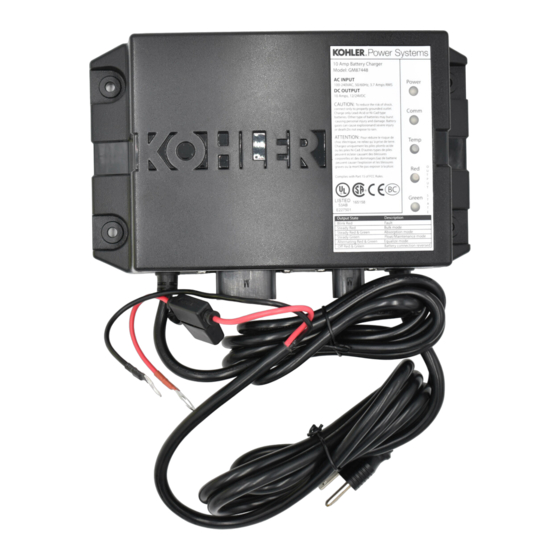
Page 10: Component Overview
User adjustable parameters to support optimal manufacturer recommended charge curve. Code compliance: UL 1236 Listed NFPA 110, Level 1 compatible (when used with Kohler controller and connected to engine harness) CSA – C22.2 No. 107.2-01 FCC – Title 47, Part 15 Class A IBC 2015... -
Page 11: Specifications
2.3 Specifications AC Input 100–260 VAC Frequency Input 50/60 Hz DC Output 10 Amps @ 12 VDC or 10 Amps @ 24 VDC (On battery voltage regulation ±1%; current is electronically limited) Fuse Protection 15 amps ATC Battery Types Flooded Lead Acid (FLA) Gel Cell High Performance AGM Nickel-Cadmium (Ni-Cad) -
Page 12: Electrical Connections
2.4 Electrical Connections Do not add extensions to the DC output leads. Extending the leads will degrade the battery charger performance and shorten battery life. If reconnecting or servicing the battery charger, use the diagrams for 12 V and 24 V Systems. The diagrams show several connection possibilities depending on the system voltage and number of chargers. - Page 13 1 charger for either 1 or 2 batteries (typical setup) 2 chargers – 1 charger for each battery (optional setup with dual-charger harness adapter) 2 chargers – 1 charger for each set of batteries (optional setup with dual-charger harness adapter) Battery charger Negative (–) battery terminal Positive (+) battery terminal...
- Page 14 TP-7077 3/19...
-
Page 15: Operation
Section 3. Operation This section describes the battery charger operation and transition states and includes the voltage and current parameters for those states. The operation states are indicated by the LED indicator lights. Refer to the LED Indication chart in the Troubleshooting section. - Page 16 Float Charge – Float charge is the standby/maintenance charge state where the battery is held to a lower constant voltage. This state is indicated by the green output voltage LED. If the battery charger indicates that the battery voltage drops below the return-to-bulk voltage parameter level or if current exceeds 5 amps, the battery charger enters bulk charge state.
-
Page 17: Sitetech™ Settings
3.2 SiteTech™ Settings To adjust settings in SiteTech™, use the following three key parameters: Charger System Battery Voltage (12 V or 24 V) Charger Starter Battery Topology (Default, FLA, AGM, Gel, NiCad) Charger Custom Profile Enable (Active, Inactive) Upon startup, the topology parameter is typically set to Default or the charger settings saved in the generator controller. - Page 18 Parameter Name Battery Type Range Default Settings Description AGM 12 V -40 – 0 AGM 24 V -80 – 0 Gel 12 V -40 – 0 Gel 24 V -80 – 0 NiCad 12 V -40 – 0 NiCad 24 V -80 –...
- Page 19 Parameter Name Battery Type Range Default Settings Description Charger Absorption Default 12 V 1 – 5 Target absorption termination setpoint that Current Termination controls when the absorption cycle Default 24 V 1 – 5 Target (A) completes. Loads on the battery controller, FLA 12 V 1 –...
- Page 20 Parameter Name Battery Type Range Default Settings Description Charger Maximum Default 12 V 60 – 360 The setting for the maximum amount of time Absorption Time the battery attempts to complete the Default 24 V 60 – 360 Threshold (Min.) absorption cycle.
-
Page 21: Maintenance
Section 4. Maintenance Periodically clean both battery terminals with baking soda and tighten all connections. No other maintenance on the battery charger is required. Section 5. Troubleshooting This section describes general troubleshooting for the battery charger. Use the following troubleshooting procedure and the LED indication chart to verify power, communication, and look for wiring harness shorts and grounds. -
Page 22: Led Indicator Lights
The five LED lights indicate the status of power, communication, and temperature as well as operation states and faults. Use the LED lights to determine the charge state and troubleshoot the battery charger. voltage output state LEDRED voltage output state LEDTemperature LEDCommunication LEDPower GM87448- GM87448G M94439- Figure 4... -
Page 23: Fcc Class B Emc Notice
Section 6. FCC Class B EMC Notice This equipment has been tested and found to comply with the limits for a Class B digital device, pursuant to Part 15 of the FCC Rules. These limits are designed to provide reasonable protection against harmful interference in a residential installation. - Page 24 KOHLER CO. Kohler, Wisconsin 53044 Phone 920-457-4441, Fax 920-459-1646 TP-7077 3/19b For the nearest sales/service outlet in the US and Canada, phone 1-800-544-2444 KOHLERPower.com © 2017, 2018, 2019 by Kohler Co. All rights reserved.
Need help?
Do you have a question about the GM87448 and is the answer not in the manual?
Questions and answers