Advertisement
Quick Links
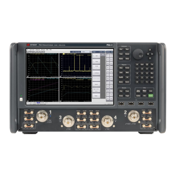
Keysight
Add 4-Port Capability
For Version 6,
Single-Source
Synthesizers
Upgrade Kit
To Upgrade PNA-X N5244B or
N5245B Option 224 to
Option 423
Upgrade Kit Order Numbers:
N5244BU- 623 and
N5245BU- 623
Keysight Kit Number:
N5245-60117
This is an Installation Note for the N5244/45B Option 224 to 423 Microwave Vector Network Analyzers
with serial numbers prefixed MY/SG/US5201 and above.
INSTALLATION GUIDE
)
Advertisement

Related Manuals for Keysight N5245-60117


Summary of Contents for Keysight N5245-60117
- Page 1 Option 423 Upgrade Kit Order Numbers: N5244BU- 623 and N5245BU- 623 Keysight Kit Number: N5245-60117 This is an Installation Note for the N5244/45B Option 224 to 423 Microwave Vector Network Analyzers with serial numbers prefixed MY/SG/US5201 and above. INSTALLATION GUIDE...
-
Page 2: Safety Notices
DOCUMENT OR ANY INFORMATION reproduce, release, perform, CONTAINED HEREIN. SHOULD display, or disclose commercial KEYSIGHT AND THE USER HAVE A computer software or SEPARATE WRITTEN AGREEMENT commercial computer software WITH WARRANTY TERMS documentation. No additional... - Page 5 Keysight Add 4-Port Capability Upgrade Kit Upgrade Kit Number: N5245-60117 Installation Note Description of the Upgrade If you had an A model PNA-X with Option 219/419 with Option H85 that was upgraded to a B model, please refer to Options 217/417. If you had an A model PNA-X with Option 224/423 with Option H85 that was upgraded to a B model then refer to Option 222/422.
-
Page 6: Contacting Keysight
Getting Assistance from Keysight Installing this upgrade kit requires special skills and experience. If you think you may not be qualified to do the work, or need advice, contact Keysight. Contacting Keysight Assistance with test and measurements needs and information on finding a local Keysight office are available on the Web at: http://www.keysight.com/find/assist... -
Page 7: Getting Prepared
Getting Prepared Getting Prepared The PNA-X contains extremely sensitive components that can be ruined if mishandled. Follow instructions carefully when making cable connections, especially wire harness connections. The person performing the work accepts responsibility for the full cost of the repair or replacement of damaged components. IMPORTANT! This document contains references to legacy A27/A28 mixer brick —... - Page 8 The enclosed Software Entitlement Certificate is a receipt, verifying that you have purchased a licensed option for the PNA-X of your choice. You must now use a Keysight Web page to request a license key file for the instrument that will receive the option.
- Page 9 1. Go to www.keysight.com. 2. In the Search box, enter the model number of the analyzer (e.g., N5225B) and click Search. 3. Click Support > Keysight Product Support. 4. In the Search Support area type your instrument’s model number (e.g., N2225B).
-
Page 10: Tools Required For The Installation
9 mm nutsetter or open end torque wrench set to 21 in-lb. About Installing the Upgrade Products affected N5244B and N5245B Option 224 Installation to be performed by Keysight service center or personnel qualified by Keysight Estimated installation time 5 hours Estimated adjustment time... - Page 11 Items Included in the Upgrade Kit Check the contents of your kit against the following list. If any part is missing or damaged, contact Keysight Technologies. Refer to “Getting Assistance from Keysight” on page Table 1 Contents of Upgrade Kit N5245-60117...
- Page 12 Table 1 Contents of Upgrade Kit N5245-60117 Description Part Number Desig. Machine screw, M3.0 x 6, pan head (4 to attach 2 receiver attenuator/bracket assy. to 0515-0430 deck; 2 to attach switch/bracket assy to deck; 4 to attach 2 source attenuator/bracket assy to deck) Machine screw, M3.0 x 25, pan head (3 to attach mixer brick A28 to mounting block)
- Page 13 Table 1 Contents of Upgrade Kit N5245-60117 Description Part Number Desig. A31 port 4 ref coupler to front-panel REF 4 SOURCE OUT N5245-20117 A35 port 4 coupler to front-panel Port 4 CPLR ARM N5245-20018 A36 port 2 coupler to front-panel Port 2 CPLR ARM...
- Page 14 Table 1 Contents of Upgrade Kit N5245-60117 Description Part Number Desig. Port 3 RCVR C IN to A47 port 3 receiver attenuator N5245-20073 W100 A47 port 3 receiver attenuator to A28 mixer brick (C) N5245-20066 W101 Port 4 RCVR D IN to A48 port 4 receiver attenuator...
-
Page 15: Overview Of The Installation Procedure
Installation Procedure for the Upgrade Installation Procedure for the Upgrade The network analyzer must be in proper working condition prior to installing this option. Any necessary repairs must be made before proceeding with this installation. This installation requires the removal of the analyzer’s protective outer covers. - Page 16 If the model number, serial number, or option number do not match those on your license key file, you will not be able to install the option. If this is the case, contact Keysight for assistance before beginning the installation of this upgrade. Refer to “Contacting Keysight” on page 6 Step 2.
-
Page 17: Step 4. Remove The Front Panel Assembly
Installation Procedure for the Upgrade Step 3. Remove the Inner Cover For instructions, click the Chapter 7 bookmark “Removing the Covers” in the PDF Service Guide Step 4. Remove the Front Panel Assembly For instructions, click the Chapter 7 bookmark “Removing and Replacing the Front Panel Assembly”... - Page 18 Installation Procedure for the Upgrade location of the other cables, click the Chapter 6 bookmark “Bottom RF Cables, 2-Port, Option 224, S/N Prefixes <6021” in the PDF Service Guide Reference Part Number Description Type Designator N5245-20036 A7 port 1 doubler to W105 N5245-20036 A12 port 3 doubler to W14 N5245-20036...
- Page 19 Installation Procedure for the Upgrade Step 8. Remove the A27 Mixer Brick Assembly Remove the A27 mixer brick assembly from the PNA-X. For instructions, click the Chapter 7 bookmark, “Removing and Replacing the A27 and A28 Mixer Bricks” in the PDF Service Guide Step 9.
- Page 20 Installation Procedure for the Upgrade 2. Follow the four instructions shown in Figure Figure 2 A26 Splitter Assembly (N5245-00023, 5067-4086, 0515-0372 (x3), 0515-2007 (x2)) Installation Note N5245-90117...
- Page 21 Installation Procedure for the Upgrade 3. Connect the gray flexible cables in the order shown in Figure Graphics in this document such as Figure 3 use very brief text to instruct where to connect a cable. For example, text that reads “N5242-60018 IFMUX P201 - BRK1 B”...
- Page 22 Installation Procedure for the Upgrade Step 11. Assemble the A30 and A31 Reference Coupler Assemblies Follow the instruction shown in Figure 4. New parts are listed in Table 1 on page 11 of this document. Figure 4 A30 and A31 Reference Coupler Assembly (5087-7760, N5245-00017, 0515-1602 (x8)) Step 12.
- Page 23 Installation Procedure for the Upgrade Step 14. Install the A47 and A48 Receiver Attenuator Assemblies Install the A47 and A48 receiver attenuator assemblies. For instructions, click the Chapter 7 bookmark, “Removing and Replacing the A38-A41 Source Attenuators and the A46-A49 Receiver Attenuators” in the PDF Service Guide New parts are listed in Table 1 on page 11 of this document.
- Page 24 Installation Procedure for the Upgrade Step 17. Install the Bias Tee Brackets Refer to Figure 5 for this step of the procedure. New parts are listed in Table 1 on page Figure 5 Bias Tee Brackets Installation (N5245-00011, 0515-0372) Step 18. Install the A43 and A44 Bias Tees Install the A43 and A44 bias tees.
- Page 25 Installation Procedure for the Upgrade Step 19. Assemble the A52 Port 4 Mechanical Switch Assembly Refer to Figure 6 for this step of the procedure. New parts are listed in Table 1 on page Figure 6 A52 Port 4 Mechanical Switch Assembly (N1811-60031, N5245-00014, 0515-1992) Step 20.
- Page 26 Installation Procedure for the Upgrade Step 21. Assemble the A33 - A36 Test Port Coupler Assemblies 1. Remove the A33 test port 1 coupler and A36 test port 2 coupler from the PNA-X. For instructions, click the Chapter 7 bookmark, “Removing and Replacing the A33 - A36 Test Port Couplers”...
- Page 27 Installation Procedure for the Upgrade Step 22. Install the LED Boards and Test Port Coupler Assemblies to the Test Set Front Plate 1. Remove two screws from each LED board and remove the boards from the 2-port test set front plate of the PNA-X. 2.
- Page 28 Installation Procedure for the Upgrade Step 23. Install the Coupler Plate Assembly to the Deck Follow the four instructions shown in Figure Figure 9 Coupler Plate Assembly Installation (0515-0372, 0515-1227) Installation Note N5245-90117...
- Page 29 Installation Procedure for the Upgrade Step 24. Install the Test Set Cables Follow instructions carefully when making cable connections, especially wire harness connections. Incorrect connections can destroy components, resulting in additional customer costs. Be careful not to damage the center pins of the semirigid cables. Some flexing of the cables may be necessary but do not over-bend them.
- Page 30 Installation Procedure for the Upgrade — W116 (N5245-20061)A52 port 4 mechanical switch to A31 port 4 reference coupler — W112 (N5245-20059)A51 port 3 mechanical switch to A30 port 3 reference coupler — W25 (N5245-20116) A30 port 3 ref coupler to front-panel REF 3 SOURCE * As shown in Figure 10, install clamp part number 1400-1334 to secure...
- Page 31 Installation Procedure for the Upgrade — W81 (reuse) (N5245-20029)A29 port 1 reference coupler to A38 port 1 source attenuator — W103 (reuse) (N5245-20055)Port 2 RCVR B IN to A49 port 2 receiver attenuator — W95 (reuse) (N5245-20030)Port 2 CPLR THRU to A45 port 2 bias tee —...
- Page 32 Installation Procedure for the Upgrade Figure 11 Location of Cable Clamp to Secure W29 (N5245-20117, 1400-1334) — W99 (N5245-20073) Port 3 RCVR C IN to A47 port 3 receiver attenuator — W87 (N5245-20089) Port 3 CPLR THRU to A43 port 3 bias tee —...
- Page 33 Installation Procedure for the Upgrade — W42 (reuse) (N5245-20007) REF 1 RCVR R1 IN to A37 reference mixer switch — W21 (N5245-20008) A29 port 1 reference coupler to A37 reference mixer switch * As shown in Figure 12, install cable tie part number 1400-0249 to secure W21.
- Page 34 Installation Procedure for the Upgrade — W110 (reuse) (N5245-20067) 50 port 1 mechanical switch to A54 combiner — W102 (N5245-20075)A48 port 4 receiver attenuator to A28 mixer brick (D) * Connect W102 to top D connector on the mixer bricks. —...
- Page 35 Installation Procedure for the Upgrade Step 25. Secure the Front Panel Bulkhead Connectors Follow the instruction shown in Figure 13 in this document. Figure 13 Bulkhead Connections, Front Panel Step 26. Reinstall the A24 IF Multiplexer Board For instructions, click the Chapter 7 bookmark “Removing and Replacing the A24 IF Multiplexer Board”...
- Page 36 Installation Procedure for the Upgrade Step 27. Reinstall the A23 Test Set Motherboard Follow instructions carefully when making cable connections, especially wire harness connections. Incorrect connections can destroy components, resulting in additional customer costs. 1. For instructions on reinstalling the board, click the Chapter 7 bookmark “Removing and Replacing the A23 test set motherboard”...
- Page 37 Installation Procedure for the Upgrade Step 28. Replace the Front Panel’s Lower Dress Panel Before the front panel’s lower dress panel can be replaced, the 2-port lower dress panel and the lower front panel label must be removed from the front panel assembly.
- Page 38 Installation Procedure for the Upgrade Step 29. Reinstall Front Panel Assembly For instructions on reinstalling the front panel assembly, click the Chapter 7 bookmark “Removing and Replacing the Front Panel Assembly” in the PDF Service Guide — Be sure to install the two new screws (0515-1946) in the front panel, next to test ports 3 and 4.
- Page 39 2. Right click the on the desired option and click Delete. 3. In the Keysight License Manager dialog box that appears, press or click Yes to confirm delete. 4. A message displays stating that the option removal was successful.
- Page 40 — The Network Analyzer program must not be running. — A keyboard and mouse must be connected to the network analyzer. — Refer to the license message you received from Keysight: Verify that the analyzer’s model and serial numbers match those on the license message you received from Keysight.
- Page 41 12. Disconnect the USB flash drive from the PNA–X. 13. On the analyzer, click or press to open the KLM software from your PNA-X’s Windows taskbar by pressing Start > More Programs > Keysight License Manager folder > Keysight License Manager and verify the options are correct.
- Page 42 — Press Help > About NA and verify that Option 419 is listed in the PNA-X application. If the options have not been enabled or if the option 224 license has not been removed, contact Keysight Technologies. Refer to “Getting Assistance from Keysight” on page 3.
- Page 43 To store the backup data, perform these steps: — Navigate to the EEPROM Backup Utility, located at: — Windows 7 -- C:\Program Files (x86)\Keysight\Network Analyzer\Service\eebackup.exe — Windows 10 -- C:\Program Files\Keysight\Network Analyzer\Service\eebackup.exe — Run the program.
- Page 44 PDF Service Guide If you experience difficulty with the basic functioning of the analyzer, contact Keysight. Refer to “Contacting Keysight” on page Calibration Although the analyzer functions, its performance relative to its specifications has not been verified. It is recommended that a full instrument calibration be performed using the analyzer’s internal performance test software.
- Page 45 Installation Note Xxxxx-xxxxx...
- Page 46 This information is subject to change without notice. © Keysight Technologies 2007-2022 Edition 1, November N5245-90117 www.keysight.com...
Need help?
Do you have a question about the N5245-60117 and is the answer not in the manual?
Questions and answers