Table of Contents
Advertisement
Quick Links
Advertisement
Table of Contents

Related Manuals for Gigabyte MW53-HP0


Summary of Contents for Gigabyte MW53-HP0
- Page 1 MW53-HP0 Intel Socket LGA4677 processor motherboard ® User Manual Rev. 1.0...
- Page 2 The trademarks mentioned in this manual are legally registered to their respective owners. Disclaimer Information in this manual is protected by copyright laws and is the property of GIGABYTE. Changes to the specifications and features in this manual may be made by Giga Computing without prior notice.
-
Page 3: Table Of Contents
Table of Contents MW53-HP0 Motherboard Layout ..................5 Block Diagram .........................7 Chapter 1 Hardware Installation ..................8 Installation Precautions ..................8 1-2 Product Specifications ..................9 Installing and Removing the CPU ..............11 Installing and Removing Memory ..............13 1-4-1 8-Channel Memory Configuration ................13 1-4-2 Installing and Removing a Memory Module ............14... - Page 4 2-3-5 IIO Configuration ....................64 2-3-6 Advanced Power Management Configuration ............66 2-3-7 PCH Configuration ....................68 2-3-8 Miscellaneous Configuration ..................70 2-3-9 Server ME Configuration ..................71 2-3-10 Runtime Error Logging Settings ................72 2-3-11 Power Policy ......................74 Server Management Menu ................76 2-4-1 System Event Log ....................78 2-4-2 View FRU Information ....................79 2-4-3 BMC VLAN Configuration ..................80 2-4-4 BMC Network Configuration ...................81 2-4-5 IPv6 BMC Network Configuration ................82...
-
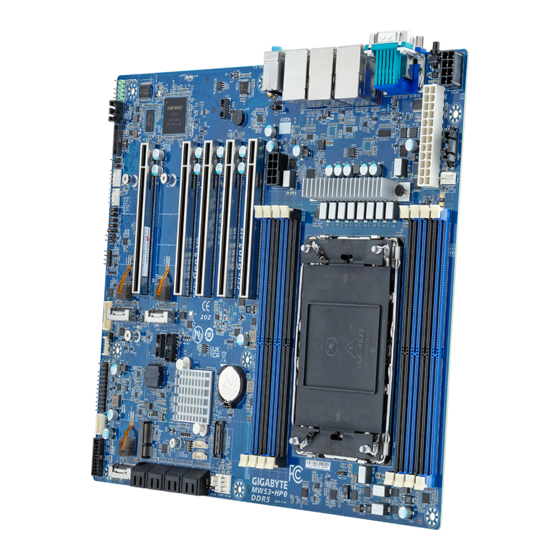
Page 5: Mw53-Hp0 Motherboard Layout
MW53-HP0 Motherboard Layout 13 12 Item Code Description AUDIO Audio Connectors USB3_MLAN Sever Management LAN Port (Top)/USB 3.2 Gen2 Type A Ports (Bottom) LAN1 2.5GbE LAN Port #1 / USB 3.2 Gen2 Type-A Ports LAN2 2.5GbE LAN Port #2 / USB 3.2 Gen2 Type-A Ports + Type-C Port... - Page 6 Item Code Description 16 SATA_2_3 Slimline Connector #2 (SATA 6Gb/s Signal) 17 SATA_0_1 Slimline Connector #1 (SATA 6Gb/s Signal) 18 M2_2 M.2 Slot (PCIe Gen4 x4, Support NGFF-2280) 19 M2E M.2 E-Key Slot (Support PCIe WIFI, Bluetooth) 20 F_USB3_V Front Panel USB 3.2 Gen1 Connector 21 IPMB IPMB Connector 22 FP_1...
-
Page 7: Block Diagram
Block Diagram - 7 -... -
Page 8: Chapter 1 Hardware Installation
Chapter 1 Hardware Installation Installation Precautions The motherboard contains numerous delicate electronic circuits and components which can become damaged as a result of electrostatic discharge (ESD). Prior to installation, carefully read the user's manual and follow these procedures: • Prior to installation, do not remove or break motherboard S/N (Serial Number) sticker or warranty sticker provided by your dealer. -
Page 9: Product Specifications
1-2 Product Specifications Intel® Xeon® W-2400 Processor Family Š Single Processor, TDP up to 225W Š 1 x LGA 4677 Š Chipset Intel® W790 Chipset Š Memory Type 8 x DIMM slots Š DDR5 memory module supported only Š 4-channel memory architecture Š... - Page 10 Š System fan Power Supply Socket Security Server Operating Properties Debian 11.5.0 Š GIGABYTE reserves the right to make any changes to the product specifications and product-related System fan Power Supply information without prior notice. Hardware Installation - 10 -...
-
Page 11: Installing And Removing The Cpu
Installing and Removing the CPU Read the following guidelines before you begin to install the CPU: • Make sure that the motherboard supports the CPU. • Always turn off the computer and unplug the power cord from the power outlet before installing the CPU to prevent hardware damage. - Page 12 Note! • The illustrations of the heat-sink installation shown are for reference only.. Hardware Installation - 12 -...
-
Page 13: Installing And Removing Memory
Installing and Removing Memory Read the following guidelines before you begin to install the memory: • Make sure that the motherboard supports the memory. It is recommended to use memory of the same capacity, brand, speed, and chips. • Always turn off the computer and unplug the power cord from the power outlet before installing the memory to prevent hardware damage. -
Page 14: Installing And Removing A Memory Module
1-4-2 Installing and Removing a Memory Module Before installing a memory module, make sure to turn off the computer and unplug the power cord from the power outlet to prevent damage to the memory module. Be sure to install DDR5 DIMMs on this motherboard. Follow these instructions to install a DIMM module: Insert the DIMM memory module vertically into the DIMM slot and push it down. -
Page 15: Installing The M.2 Ssd Module
Installing the M.2 SSD Module Follow the steps below to install a M.2 SSD module on your motherboard. Step1. Insert the M.2 SSD module into the slot. Step2. Secure it with the screw, tightening as necessary to fasten the M.2 SSD module in place. Hardware Installation - 15 -... -
Page 16: Back Panel Connectors
Back Panel Connectors ID Button with LED When the system identification is active, the ID LED on the front/ back panel glows blue. Serial Port Connect to serial-based mouse or data processing devices. VGA Port Connect to a monitor device. 2.5GbE LAN Port #2 The Gigabit Ethernet LAN port provides Internet connection at up to 2.5 Gbps data rate. See the section below for a description of the states of the LAN port LEDs. - Page 17 Connection/ 2.5GbE LAN LED: Speed LED Link/Activity LED State Description Yellow On 1 Gbps, 100Mbps data rate Green On 2.5 Gbps data rate 10 Mbps data rate LAN Port 10/100/1000 LAN LED: State Description Yellow On 1 Gbps data rate Green On 100 Mbps data rate 10 Mbps data rate...
-
Page 18: Internal Connectors
Internal Connectors P12V_AUX2 ATX1 PMBUS CPU_FAN SYS_FAN4 SYS_FAN2 F_USB3_V IPMB FP_1 BP_1 SPI_TPM SYS_FAN1 SYS_FAN3 P12V_AUX1 CN_NCSI F _AUDIO SPGIO_1_2 DB ESPI Case Open Intrusion Header BMC Firmware Readiness LED Hardware Installation - 18 -... - Page 19 Read the following guidelines before connecting external devices: • First make sure your devices are compliant with the connectors you wish to connect. • Before installing the devices, be sure to turn off the devices and your computer. Unplug the power cord from the power outlet to prevent damage to the devices.
- Page 20 1/18/2) P12V_AUX2/P12V_AUX1/ATX1 (2x4 12V Power Connector and 2x12 Main Power Connector) With the use of the power connector, the power supply can supply enough stable power to all the components on the motherboard. Before connecting the power connector, first make sure the power supply is turned off and all devices are properly installed. The power connector possesses a foolproof design. Connect the power supply cable to the power connector in the correct orientation.
- Page 21 3) PMBus Connector The Power Management Bus (PMBus) is a variant of the System Management Bus (SMBus) which is targeted at digital management of power supplies. Pin No. Definition PMBus Clock PMBus Data PMBus Alert 3.3V Sense 4/6/7/13/14) CPU_FAN/SYS_FAN4/SYS_FAN2/SYS_FAN1/SYS_FAN3/SYS_FAN5 (CPU Fan/System Fan Headers) The motherboard has one 4-pin CPU fan header (CPU_FAN), and two 4-pin (SYS_FAN) system fan headers.
- Page 22 5) BAT (Battery Scoket) The battery provides power to keep the values (such as BIOS configurations, date, and time information) in the CMOS when the computer is turned off. Replace the battery when the battery voltage drops to a low level, or the CMOS values may not be accurate or may be lost. • Always turn off your computer and unplug the power cord before replacing the battery. •...
- Page 23 8) F_USB3_V (Front Panel USB 3.2 Gen1 Connector) The connectors conform to USB 3.2 specification. Each USB header can provide two USB ports via an optional USB bracket. For purchasing the optional USB bracket, please contact the local dealer. USB 3.2 Connector Pin No.
- Page 24 10) FP_1 (Front Panel Header) Connect the power switch, reset switch, speaker, chassis intrusion switch/sensor and system status indicator on the chassis to this header according to the pin assignments below. Note the positive and negative pins before connecting the cables. Pin No.
- Page 25 12) TPM (Trusted Platform Module Connector) Trusted Platform Module (TPM) is an international standard for a secure cryptoprocessor, a dedicated microcontroller designed to secure hardware through integrated cryptographic keys. Pin No. Definition Pin No. Definition Clock No Connect P_3V3_AUX No Connect LPC_RST No Pin No Connect...
- Page 26 17) F_AUDIO (Front Panel Audio Header) The front panel audio header supports High Definition audio (HD). You may connect your chassis front panel audio module to this header. Make sure the wire assignments of the module connector match the pin assignments of the motherboard header. Incorrect connection between the module connector and the motherboard header will make the device unable to work or even damage it. Pin No.
- Page 27 19) DP ESPI Connect the DisplayPort and Enhanced Serial Peripheral Interface (ESPI) interfaces for communication be- tween a computer's chipset and a monitor's embedded controller. Definition Clock 24M_66M ESPI_CS0_N ESPI_IO0_LAD0 ESPI_RST_N ESPI_IO1_LAD1 ESPI_IO3 ESPI_IO2_LAD2 ESPI_ALERT0_N ESPI_ALERT1_N ESPI_CS1_N 20) CASE_OPEN (Case Open Intrusion Alert Header) This motherboard provides a chassis detection feature that detects if the chassis cover has beenremoved.
- Page 28 21) LED_BMC (BMC Firmware Readiness LED) This motherboard provides a chassis detection feature that detects if the chassis cover has beenremoved. This function requires a chassis with chassis intrusion detection design. State Description BMC firmware is initial Blink BMC firmware is ready AC loss Hardware Installation - 28 -...
-
Page 29: Jumper Settings
Jumper Settings No. Jumper Name Jumper Setting 1-2: Nomal operation (Default) ME Force Update 2-3: Enable ME Force Update 1-2: Enable BIOS Recovery 2-3: Default 1-2: Nomal operation (Default) Clear CMOS 2-3: Clear CMOS data 1-2: Default Password Clear 2-3: Enable Hardware Installation - 29 -... -
Page 30: Chapter 2 Bios Setup
Chapter 2 BIOS Setup BIOS (Basic Input and Output System) records hardware parameters of the system in the EFI on the motherboard. Its major functions include conducting the Power-On Self-Test (POST) during system startup, saving system parameters, loading the operating system etc. The BIOS includes a BIOS Setup program that allows the user to modify basic system configuration settings or to activate certain system features. When the power is turned off, the battery on the motherboard supplies the necessary power to the CMOS to keep the configuration values in the CMOS. - Page 31 Main This setup page includes all the items of the standard compatible BIOS. Advanced This setup page includes all the items of AMI BIOS special enhanced features. (ex: Auto detect fan and temperature status, automatically configure hard disk parameters.) Chipset This setup page includes all the submenu options for configuring the functions of the Platform Controller Hub. Server Management Server additional features enabled/disabled setup menus. ...
-
Page 32: The Main Menu
The Main Menu Once you enter the BIOS Setup program, the Main Menu (as shown below) appears on the screen. Use arrow keys to move among the items and press <Enter> to accept or enter other sub-menu. Main Menu Help The on-screen description of a highlighted setup option is displayed on the bottom line of the Main Menu. - Page 33 Parameter Description BIOS Information Project Name Displays the project name information. Project Version Displays version number of the BIOS setup utility. Build Date and Time Displays the date and time when the BIOS setup utility was created. BMC Information (Note1) BMC Firmware Version Displays BMC firmware version information. (Note1) Processor Information CPU Brand String/ Max CPU Speed Displays the technical information for the installed processor(s).
- Page 34 Parameter Description Memory Frequency Displays the frequency information of the installed memory. Onboard LAN Information (Note3) LAN# MAC Address Displays LAN MAC address information. System Date Sets the date following the weekday-month-day-year format. System Time Sets the system time following the hour-minute-second format. (Note3) The number of LAN ports listed will depend on the motherboard / system model.
-
Page 35: Advanced Menu
Advanced Menu The Advanced Menu displays submenu options for configuring the function of various hardware components. Select a submenu item, then press <Enter> to access the related submenu screen. BIOS Setup - 35 -... -
Page 36: Trusted Computing
2-2-1 Trusted Computing Parameter Description TPM 2.0 Device Found Firmware Version/ Vendor Displays the firmware version and Vendor information. Enable/Disable BIOS support for security device. OS will not show security device. TCG EFI protocol and INT1A interface will not be TPM v1.2 Support available. Options available: Disable, Enable. Default setting is Enable. Selets TPM device. - Page 37 Parameter Description Schedule an operation for the security device. NOTE: Your computer will reboot during restart in order to change the Pending operation state of a security device. Options available: None, TPM Clear. Default setting is None. Enable/Disable platform hierarchy. Platform Hierarchy Options available: Disabled, Enabled.
-
Page 38: Serial Port Console Redirection
2-2-2 Serial Port Console Redirection Parameter Description Console redirection enables the users to manage the system from a COM1 Console remote location. Redirection (Note) Options available: Enabled, Disabled. Default setting is Disabled. Press [Enter] to configure advanced items. Please note that this item is configurable when COM1 Console Redirection is set to Enabled. Terminal Type Š... - Page 39 Parameter Description Parity Š – A parity bit can be sent with the data bits to detect some transmission errors. – Even: parity bit is 0 if the num of 1's in the data bits is even. – Odd: parity bit is 0 if num of 1's in the data bits is odd. –...
- Page 40 Parameter Description Serial Port for Out-of-Band Management / Windows EMS console redirection allows the user to configure Console Redirection Emergency Management Settings to support Out-of-Band Serial Port management. Services (EMS) Console Options available: Enabled, Disabled. Default setting is Disabled. Redirection (Note) Press [Enter] to configure advanced items. Please note that this item is configurable when Serial Port for Out-of- Band Management EMS Console Redirection is set to Enabled. Out-of-Band Mgmt Port Š...
-
Page 41: Sio Configuration
2-2-3 SIO Configuration Description Parameter Displays the AMI SIO driver version information. AMI SIO Driver Version Super IO Chip Logical Device(s) Configuration Press [Enter] to configure advanced items. Use This Device Š – When set to Enabled allows you to configure the serial port settings. When set to Disabled, displays no configuration for the serial port. – Options available: Enabled, Disabled. Default setting is Enabled. Logical Device Settings/Current: Š... -
Page 42: Pci Subsystem Settings
2-2-4 PCI Subsystem Settings BIOS Setup - 42 -... - Page 43 Parameter Description PCI Bus Driver Version Displays the PCI Bus Driver version information. When enabled, this setting will initialize the device expansion PCIE_# I/O ROM ROM for the related PCI-E slot. (Note1) Options available: Enabled, Disabled. Default setting is Enabled. PCIE_# Lanes Change the PCIe lanes.
-
Page 44: Usb Configuration
2-2-5 USB Configuration Parameter Description USB Configuration USB Devices: Displays the USB devices connected to the system. Enable/Disable the XHCI (USB 3.0) Hand-off support. XHCI Hand-off Options available: Enabled, Disabled. Default setting is Enabled. USB Mass Storage Driver Enable/Disable the USB Mass Storage Driver Support. Support (Note) Options available: Enabled, Disabled. -
Page 45: Network Stack Configuration
2-2-6 Network Stack Configuration Parameter Description Enable/Disable the UEFI network stack. Network Stack Options available: Enabled, Disabled. Default setting is Enabled. Enable/Disable the Ipv4 PXE feature. Ipv4 PXE Support Options available: Enabled, Disabled. Default setting is Enabled. Enable/Disable the Ipv4 HTTP feature. Ipv4 HTTP Support Options available: Enabled, Disabled. -
Page 46: Post Report Configuration
2-2-7 Post Report Configuration Parameter Description Post Report Configuration Error Message Report Enable/Disable the POST Error Message support. Post Error Message Options available: Enabled, Disabled. Default setting is Enabled. Halt On Options available: No Error, All Error. Default setting is No Error. BIOS Setup - 46 -... -
Page 47: Nvme Configuration
2-2-8 NVMe Configuration Parameter Description NVMe Configuration Displays the NVMe devices connected to the system. Options available: BIOS Build-In, NVMe Device. Default setting is BIOS NVMe OPROM Select Build-In. BIOS Setup - 47 -... -
Page 48: Chipset Configuration
2-2-9 Chipset Configuration Parameter Description Defines the power state to resume to after a system shutdown that is due to an interruption in AC power. When set to Last State, the system will return to the active power state prior to shutdown. When set to Restore on AC Power Loss (Note) Power Off, the system remains off after power shutdown. Options available: Last State, Power Off, Power On, Unspecified. The default setting depends on the BMC setting. -
Page 49: Tls Auth Configuration
2-2-10 Tls Auth Configuration Parameter Description Press [Enter] for configuration of advanced items. Enroll Cert Š – Press [Enter] to enroll a certificate • Enroll Cert Using File • Cert GUID Server CA Configuration Input digit character in 1111111-2222-3333-4444-1234567890ab format. – Commit Changes and Exit – Discard Changes and Exit Delete Cert Š Press [Enter] for configuration of advanced items. Client Cert Configuration BIOS Setup - 49 -... -
Page 50: Iscsi Configuration
2-2-11 iSCSI Configuration Parameter Description Press [Enter] configure advanced items. Attempt Priority Š Attempt Priority – Use arrow keys to select the attempt, then press +/- keys to move the attempt up/down in the attempt order list. Commit Changes and Exit Š Press [Enter] to configure advanced items. iSCSI Initiator Name Š... -
Page 51: Intel(R) Ethernet Controller X710 For 10Gbase-T
2-2-12 Intel(R) Ethernet Controller X710 for 10GBASE-T BIOS Setup - 51 -... - Page 52 Description Parameter Press [Enter] to configure advanced items. Link Speed Š – Default setting is Auto Negotiated. Wake On LAN Š – Enables power on of the system via LAN. Note that configuring Wake on LAN in the operating system does not change the value of NIC Configuration this setting, but does override the behavior of Wake on LAN in OS controlled power states.
-
Page 53: Vlan Configuration
2-2-13 VLAN Configuration Parameter Description Press [Enter] to configure advanced items. Create new VLAN Š VLAN ID Š – Sets VLAN ID for a new VLAN or an existing VLAN. – Press the <+> / <-> keys to increase or decrease the desired values. – The valid range is from 0 to 4094. Priority Š... -
Page 54: Driver Health
2-2-14 Driver Health Parameter Description Driver Health Displays driver health status of the devices/controllers if installed. BIOS Setup - 54 -... -
Page 55: Chipset Menu
Chipset Menu Chipset Setup menu displays submenu options for configuring the function of Platform Controller Hub(PCH). Select a submenu item, then press <Enter> to access the related submenu screen. BIOS Setup - 55 -... - Page 56 2-3-1 Processor Configuration BIOS Setup - 56 -...
-
Page 57: Processor Configuration
Description Parameter Processor Configuration Press [Enter] to configure advanced items. CPU Socket 0 Configuration Š – Core Disable Bitmap(Hex) • Number of Cores to enable. 0 means all cores. FFFFFFF Pre-Socket Configuration means to disable all cores. The maximum value depends on the number of CPUs available. Press the numeric keys to adjust desired values. - Page 58 Description Parameter Enable/Disable memory encryption (TME). Memory Encryption (TME) (Note) Options available: Enabled, Disabled. Default setting is Disabled. Total Memory Encryption Options available: Enabled, Disabled. Default setting is Disabled. Multi-Tenant (TME-MT) Press [Enter] to configure advanced items. Provision S3M CFR Š – Options available: Disable, Enable. Default setting is Enable. Manual Commit S3M FW CFR Š...
-
Page 59: Common Refcode Configuration
2-3-2 Common RefCode Configuration Parameter Description Common RefCode Configuration Numa Default setting is Enable. Divide physical NUMA nodes into evenly sized virtual NUMA nodes in ACPI table. This may improve Windows performance on CPUs Virtual Numa with more than 64 logical processors. Options available: Enable, Disable. Default setting is Disable. BIOS Setup - 59 -... -
Page 60: Upi Configuration
2-3-3 UPI Configuration Description Parameter Press [Enter] to configure advanced items. UPI Status Š – Press [Enter] to view the Uncore status. Š – Enable/Disable Sub NUMA Cluster function. – Options available: Auto, Disable, Enable SNC2 (2-clusters), Enable SNC4 (4-clusters). Default setting is Auto. Stale AtoS Š... -
Page 61: Memory Configuration
2-3-4 Memory Configuration Description Parameter Integrated Memory Controller (iMC) When set to Enable, the system enforces Plan Of Record restrictions for DDR frequency programming. Enforce DDR Memory Frequency POR Options available: POR, Disable. Default setting is POR. Configures the maximum memory frequency. If Enforce POR is disabled, user will be able to run at higher frequencies than the Memory Frequency memory support (limited by processor support). - Page 62 Description Parameter Press [Enter] to configure advanced items. Mirror Mode (Note) Š – Mirror Mode will set entire 1LM memory in system to be mirrored, consequently reducing the memory capacity by half. Enables the Mirror Mode will disable the XPT Prefetch. – Options available: Disabled, Full Mirror Mode, Partial Mirror Mode.
- Page 63 Description Parameter Leaky bucket time window based interface Minute Š – Leaky bucket time window based interface minute used for DDR (0-60). – Press the <+> / <-> keys to increase or decrease the desired values. Leaky bucket low bit Š...
-
Page 64: Iio Configuration
2-3-5 IIO Configuration Description Parameter IIO Configuration Press [Enter] to configure advanced items. ® Intel VT for Directed I/O Š – Enable/Disable the Intel VT for Directed I/O (VT-d) support function by reporting the I/O device assignment to VMM through DMAR ACPI Tables. – Options available: Enable, Disable. Default setting is Enable. ACS Control Š... - Page 65 Description Parameter DMA Control Opt-In Flag Š – Enable/Disable DMA_CTRL_PLATFORM_OPT_IN_FLAG in DMAR table in ACPI. Not compatible with Direct Device Assignment (DDA). – Options available: Enable, Disable. Default setting is Disable. Interrupt Remapping Š – Enable/Disable the interrupt remapping support function. –...
-
Page 66: Advanced Power Management Configuration
2-3-6 Advanced Power Management Configuration Description Parameter Press [Enter] to configure advanced items. SpeedStep (Pstates) Š – Conventional Intel SpeedStep Technology switches both voltage and frequency in tandem between high and low levels in response to processor load. – Options available: Enable, Disable. Default setting is Enable. CPU P State Control Turbo Mode Š... - Page 67 Description Parameter Press [Enter] to configure advanced items. Enable Monitor MWAIT Š – Allows Monitor and MWAIT instructions. – Options available: Disable, Enable, Auto. Default setting is Auto. CPU C6 Report Š CPU C State Control – Enable/Disable CPU C6(ACPI C3) report to OS. – Options available: Disable, Enable, Auto. Default setting is Auto. Enhanced Halt State (C1E) Š...
-
Page 68: Pch Configuration
2-3-7 PCH Configuration Description Parameter PCH-IO Configuration SATA Controller And RST Configuration Š – Press [Enter] to configure advanced items. • SATA Configuration » Enable/Disable SATA controller. » Options available: Enabled, Disabled. Default setting is Enabled. • SATA Mode Selection » Configures on chip SATA type. » AHCI Mode: When set to AHCI, the SATA controller enables its AHCI functionality. - Page 69 Description Parameter • SATA Port 0/1/2/3/4/5/6/7 » The category identifies SATA hard drives that are installed in the computer. System will automatically detect HDD type. • Port 0/1/2/3/4/5/6/7 » Enable/Disable Port 0/1/2/3/4/5/6/7 device. » Options available: Enabled, Disabled. Default setting is Enabled. • Hot Plug (for Port 0/1/2/3/4/5/6/7) » Enable/Disable HDD Hot-Plug function. »...
-
Page 70: Miscellaneous Configuration
2-3-8 Miscellaneous Configuration Description Parameter Miscellaneous Configuration Selects the active video type. Options available: Auto, Onboard Device, PCIE Device, Specific PCIE Active Video Device. Default setting is Auto. Enables this knob to disable IO decode on second GPU in a Dual GPU Disable IO decode for Second ML Config. Options available: Enabled, Disabled. Default setting is Disabled. BIOS Setup - 70 -... -
Page 71: Server Me Configuration
2-3-9 Server ME Configuration Parameter Description ME Firmware Version Displays the operational firmware version. ME Firmware Mode Displays the operational firmware mode. ME Firmware SKU Disaplays ME firmware sku information. ME Firmware Status #1/#2 Displays ME firmware status information. ME State Default setting is Enabled. Press [Enter] to configure advanced items. Me FW Image Re-Flash Š Firmware Update Configuration – Enable/Disable ME firmware image re-flash function. – Options available: Disabled, Enabled. Default setting is Disabled. -
Page 72: Runtime Error Logging Settings
2-3-10 Runtime Error Logging Settings Description Parameter Runtime Error Logging Enable/Disable system error logging function. System Errors Options available: Enable, Disable. Default setting is Enable. Press [Enter] to configure advanced items. WHEA (Windows Hardware Error Architecture) Support Š Whea Settings – Enable/Disable WHEA Support. – Options available: Enable, Disable. Default setting is Enable. Press [Enter] to configure advanced items. - Page 73 Description Parameter Uncorrected Error (Note) Š – Enables and escalates Uncorrectable/Recoverable Errors to error pins. – Options available: Enable, Disable. Default setting is Enable. Fatal Error Enable (Note) Š – Enables and escalates Fatal Errors to error pins. – Options available: Enable, Disable. Default setting is Enable. Assert NMI on SERR (Note) Š...
-
Page 74: Power Policy
2-3-11 Power Policy Description Parameter Selects a Power Policy Quick Setting. Options available: Standard, Best Performance, Energy Efficient. Default Power Policy Quick Settings setting is Standard. Conventional Intel SpeedStep Technology switches both voltage and frequency in tandem between high and low levels in response to processor SpeedStep (Pstates) load. - Page 75 Description Parameter Enables Logical processor (Software Method to Enable/Disable Logical Processor threads). Enable LP [Global] Options available: ALL LPs, Single LP. Default setting is ALL LPs. Options available: Enable, Disable. Default setting is Enable. Hardware Prefetcher Options available: Enable, Disable. Default setting is Enable. Adjacent Cache Prefetch Options available: Enable, Disable.
-
Page 76: Server Management Menu
Server Management Menu Parameter Description Enable/Disable FRB-2 timer (POST timer). FRB-2 Timer Options available: Enabled, Disabled. Default setting is Enabled. FRB-2 Timer Configures the FRB2 Timer timeout. The value is between 1 to 30 minutes. (Note1) timeout Default setting is 6 minutes. Configures the FRB2 Timer policy. FRB-2 Timer Options available: Do Nothing, Reset, Power Down, Power Cycle. Policy (Note1) Default setting is Do Nothing. - Page 77 Parameter Description System Event Log Press [Enter] to configure advanced items. View FRU Press [Enter] to view the FRU information. Information BMC VLAN Press [Enter] to configure advanced items. Configuration BMC network Press [Enter] to configure advanced items. Configuration IPv6 BMC Network Press [Enter] to configure advanced items. Configuration BIOS Setup - 77 -...
-
Page 78: System Event Log
2-4-1 System Event Log Parameter Description Enabling / Disabling Options Change this item to enable or disable all features of System Event SEL Components Logging during boot. Options available: Enabled, Disabled. Default setting is Enabled. Erasing Settings Choose options for erasing SEL. Options available: No, Erase SEL Yes, On next reset,... -
Page 79: View Fru Information
2-4-2 View FRU Information The FRU page is a simple display page for basic system ID information, as well as System product information. Items on this window are non-configurable. (Note) The model name will vary depends on the product you purchased BIOS Setup - 79 -... -
Page 80: Bmc Vlan Configuration
2-4-3 BMC VLAN Configuration Description Parameter BMC VLAN Configuration Select to configure BMC VLAN ID. The valid range is from 0 to 4094. When BMC VLAN ID set to 0, BMC VLAN ID will be disabled. Select to configure BMC VLAN Priority. The valid range is from 0 to 7. BMC VLAN Priority When BMC VLAN ID is set to 0, BMC VLAN Priority will not be selected. BIOS Setup - 80 -... -
Page 81: Bmc Network Configuration
2-4-4 BMC Network Configuration Parameter Description BMC network configuration Select NCSI and Dedicated Options available: Do Nothing, Model1(Dedicated), Model2(NCSI), Mode3(Failover). Default setting is Do Nothing. Lan Channel 1 Selects to configure LAN channel parameters statically or dynamically (DHCP). Configuration Address source Options available: Unspecified, Static, DynamicBmcDhcp. Default setting is DynamicBmcDhcp. Station IP address Displays IP Address information. Displays Subnet Mask information. Subnet mask Please note that the IP address must be in three digitals, for example, 192.168.000.001. -
Page 82: Ipv6 Bmc Network Configuration
2-4-5 IPv6 BMC Network Configuration Parameter Description IPv6 BMC network configuration IPv6 BMC Lan Channel 1 Enable/Disable IPv6 BMC LAN channel function. When this item is disabled, the system will not modify any BMC network during BIOS IPv6 BMC Lan Option phase. Options available: Unspecified, Disable, Enable. Default setting is Enable. Selects to configure LAN channel parameters statically or dynamically (by BIOS or BMC). IPv6 BMC Lan IP Address Options available: Unspecified, Static, Dynamic-Obtained by BMC Source... -
Page 83: Security Menu
Security Menu The Security menu allows you to safeguard and protect the system from unauthorized use by setting up access passwords. There are two types of passwords that you can set: • Administrator Password Entering this password will allow the user to access and change all settings in the Setup Utility. •... -
Page 84: Secure Boot
2-5-1 Secure Boot The Secure Boot submenu is applicable when your device is installed the Windows 8 (or above) operating ® system. Parameter Description System Mode Displays if the system is in User mode or Setup mode. Enable/ Disable the Secure Boot function. Secure Boot Options available: Enabled, Disabled. - Page 85 Parameter Description Press [Enter] to configure advanced items. Please note that this item is configurable when Secure Boot Mode is set to Custom. Factory Key Provision Š – Allows to provision factory default Secure Boot keys when system is in Setup Mode. – Options available: Enabled, Disabled. Default setting is Disabled. Restore Factory Keys Š – Installs all factory default keys. It will force the system in User Mode. –...
- Page 86 Parameter Description Authorized TimeStamps (DBT) Š – Displays the current status of the Authorized TimeStamps Database. – Press [Enter] to configure a new DBT or load additional DBT from storage devices. Key Management – Options available: Update, Append. (continued) OsRecovery Signatures Š – Displays the current status of the OsRecovery Signature Database. –...
-
Page 87: Boot Menu
Boot Menu The Boot menu allows you to set the drive priority during system boot-up. BIOS setup will display an error message if the legacy drive(s) specified is not bootable. Parameter Description Boot Configuration Number of seconds to wait for setup activation key. 65535 (0xFFFF) Setup Prompt Timeout means indefinite waiting. Press the numeric keys to input the desired values. - Page 88 Parameter Description FIXED BOOT ORDER Priorities Press [Enter] to configure the boot order priority. By default, the server searches for boot devices in the following sequence: Hard drive. Boot Option #1 / #2 / #3 / #4 / #5 CD-COM/DVD drive. USB device. Network. UEFI. UEFI Network Drive BBS Press [Enter] to configure the boot priority.
-
Page 89: Save & Exit Menu
Save & Exit Menu The Save & Exit menu displays the various options to quit from the BIOS setup. Highlight any of the exit options then press <Enter>. Parameter Description Save Options Saves changes made and closes the BIOS setup. Save and Exit Options available: Yes, No. - Page 90 Parameter Description Loads the default settings for all BIOS setup parameters. Setup Defaults are quite demanding in terms of resources consumption. If you are using low-speed memory chips or other kinds of low-performance components Restore Default Values and you choose to load these settings, the system might not function properly.
-
Page 91: Bios Recovery
BIOS Recovery The system has an embedded recovery technique. In the event that the BIOS becomes corrupt the boot block can be used to restore the BIOS to a working state. To restore your BIOS, please follow the instructions listed below: Recovery Instruction: 1. -
Page 92: Bios Post Beep Code (Ami Standard)
BIOS POST Beep code (AMI standard) 2-9-1 PEI Beep Codes # of Beeps Description Memory not Installed. Memory was installed twice (InstallPeiMemory routine in PEI Core called twice) Recovery started DXEIPL was not found DXE Core Firmware Volume was not found Recovery failed S3 Resume failed Reset PPI is not available...
Need help?
Do you have a question about the MW53-HP0 and is the answer not in the manual?
Questions and answers