Table of Contents
Advertisement
Quick Links
Advertisement
Table of Contents

Related Manuals for Gigabyte MW32-SP0


Summary of Contents for Gigabyte MW32-SP0
- Page 1 MW32-SP0 Intel Socket LGA1151 processor motherboard ® User's Manual Rev. 1001...
- Page 2 GIGABYTE's prior written permission. Documentation Classifications In order to assist in the use of this product, GIGABYTE provides the following types of documentation: For detailed product information, carefully read the User's Manual.
-
Page 3: Table Of Contents
Table of Contents MW32-SP0 Motherboard Layout ..................5 Block Diagram .........................7 Chapter 1 Hardware Installation ..................8 Installation Precautions ..................8 1-2 Product Specifications ..................9 Installing the CPU and CPU Cooler ............... 11 1-3-1 Installing the CPU ....................11 1-3-2 Installing the CPU Cooler ..................13 Installing the Memory .................. - Page 4 2-7-1 AMI Standard - PEI ....................58 2-7-2 AMI Standard - DXE ....................58 2-7-3 AMI Standard - ERROR ..................60 2-7-4 Intel UPI POST Codes ....................61 2-7-5 Intel UPI Error Codes .....................61 2-7-6 Intel MRC POST Codes ..................62 2-7-7 Intel MRC Error Codes ...................62 2-7-8 Intel PM POST Codes ....................63 2-7-9...
-
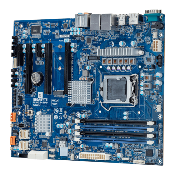
Page 5: Mw32-Sp0 Motherboard Layout
MW32-SP0 Motherboard Layout 36 37 38 DIMM_P0_A0 DIMM_P0_A1 DIMM_P0_B0 DIMM_P0_B1 - 5 -... - Page 6 Item Code Description HD_AUDIO Audio Connectors USB3_LAN1 GbE Ethernet LAN Port #1(top) / USB3.1 Ports (bottom) USB3_LAN2 GbE Ethernet LAN Port #2(top) / USB3.1 Ports (bottom) R_USB2 USB 2.0 Ports DP_HDMI Display Port (top) / HDMI Port (bottom) COM1 Serial Port SYS_FAN0 System Fan Connector #0 P12V_AUX1...
-
Page 7: Block Diagram
Block Diagram - 7 -... -
Page 8: Chapter 1 Hardware Installation
Chapter 1 Hardware Installation Installation Precautions The motherboard contains numerous delicate electronic circuits and components which can become damaged as a result of electrostatic discharge (ESD). Prior to installation, carefully read the user's manual and follow these procedures: • Prior to installation, do not remove or break motherboard S/N (Serial Number) sticker or warranty sticker provided by your dealer. -
Page 9: Product Specifications
1-2 Product Specifications Supports Intel® Xeon® E-2100 Processors Š 8th Gen. Intel Core™ i3/ Pentium®/ Celeron® Processors Š Chipset Intel® C246 Express Chipset Š Memory 4 x DIMM slots Š Dual channel memory architecture Š Supports 1.2V DDR4 memory Š ECC UDIMM modules supported Š... - Page 10 1 x Optical S/PDIF-Out Š 1 x TPM header Š Š Form Factor 305mm W x 244mm D Š GIGABYTE reserves the right to make any changes to the product specifications and product-related information without prior notice. Hardware Installation - 10 -...
-
Page 11: Installing The Cpu And Cpu Cooler
Installing the CPU and CPU Cooler Read the following guidelines before you begin to install the CPU: • Make sure that the motherboard supports the CPU. • Always turn off the computer and unplug the power cord from the power outlet before installing the CPU to prevent hardware damage. - Page 12 B. Follow the steps below to correctly install the CPU into the motherboard CPU socket. Before installing the CPU, make sure to turn off the computer and unplug the power cord from the power outlet power plug to prevent any damage to prevent damage to the CPU. Step 1: Step 2: Gently press the CPU socket lever handle down...
-
Page 13: Installing The Cpu Cooler
1-3-2 Installing the CPU Cooler Follow the steps below to correctly install the CPU cooler on the motherboard. (The following procedure uses Intel boxed cooler as the example cooler.) ® Male Push Direction of the Arrow Sign on The Top the Male Push of Female Push Pin... -
Page 14: Installing The Memory
Installing the Memory Read the following guidelines before you begin to install the memory: • Make sure that the motherboard supports the memory. It is recommended to use memory of the same capacity, brand, speed, and chips. • Always turn off the computer and unplug the power cord from the power outlet before installing the memory to prevent hardware damage. -
Page 15: Installing The M.2 Ssd Module
Installing the M.2 SSD Module Follow the steps below to install a M.2 SSD module on your motherboard. Step1. Insert the M.2 SSD module into the slot. Step2. Secure it with the screw, tightening as necessary to fasten the M.2 SSD module in place. - 15 - Hardware Installation... -
Page 16: Back Panel Connectors
Back Panel Connectors Serial Port Connects to serial-based mouse or data processing devices. Display Port DisplayPort delivers high quality digital imaging and audio, supporting bi-directional audio transmission. DisplayPort can support both DPCP and HDCP 2.2 content protection mechanisms. It provides improved visuals supporting Rec. -
Page 17: Back Panel Connectors
Line In Jack (Blue) The default Line in jack. Use this audio jack for line in devices such as an optical drive, walkman, etc Line Out Jack (Green) The default Line Out jack. Use this audio jack for a headphone or 2-channel speaker. This jack can be used to connect front speakers in a 4/5.1/7.1-channel audio configuration. Mic In (Pink) The default MIC In jack. A microphone can be connected to the MIC In jack. Connection/ Connection/Speed LED: Activity LED: Speed LED Link/Activity LED State Description State Description Yellow On 1 Gbps data rate Blinking Data transmission or receiving is occurring Green On 100 Mbps data rate No data transmission or receiving is occurring... -
Page 18: Internal Connectors
Internal Connectors DIMM_P0_A0 DIMM_P0_A1 DIMM_P0_B0 DIMM_P0_B1 15) SYS_FAN2 ATX_12V 16) SYS_FAN3 SATA0 (Support SATA DOM Power) 17) PMBUS SATA1(Support SATA DOM Power) 18) F_USB3 SATA2/SATA3 19) F_USB2 SATA4/SATA5 20) F_USB2_2 SATA6/SATA7 21) COM2 SATA8/SATA9 22) BP_1 SATA_DOM0 23) TPM 10) SATA_DOM1 24) FP_1 11) SATA_SGP1/SATA_SGP2 25) F_AUDIO... - Page 19 1/2) ATX/ATX_12V (2x12 Main Power Connector and 2x4 12V Power Connector) With the use of the power connector, the power supply can supply enough stable power to all the components on the motherboard. Before connecting the power connector, first make sure the power supply is turned off and all devices are properly installed. The power connector possesses a foolproof design. Connect the power supply cable to the power connector in the correct orientation.
- Page 20 3/4/5/6/7/8) SATA0/SATA1/SATA2/SATA3/SATA4/SATA5/SATA6/SATA7/SATA8/SATA9 (SATA 6Gb/s Connectors) The SATA connectors conform to SATA 6Gb/s standard and are compatible with SATA 3Gb/s standard. Each SATA connector supports a single SATA device. Pin No. Definition SATAIII_0 SATA0 SATA2 SATA3 SATA1 SATA5 SATAIII_2 SATAIII_3 SATA4 SATA8 SATA6 SATA9 SATA7 SATAIII_1...
- Page 21 11) SATA_SGP1/ SATA_SGP2(SATA SGPIO) Connector Serial General Purpose Input/Output (SGPIO) is a communication method used between a host bus adapter (HBA) and a main board.Ommoleni dolor moluptaeria pella peritio. Unt. Pin No. Definition Data Out Ground No Connect Load SATA_SGP1 Clock SATA_SGP2 12/13/14/15/16) CPU_FAN/ SYS_FAN0/ SYS_FAN1/ SYS_FAN2/ SYS_FAN3 (CPU Fan/System Fan Headers)
- Page 22 17) PMBus Connector The Power Management Bus (PMBus) is a variant of the System Management Bus (SMBus) which is targeted at digital management of power supplies. PMBus Pin No. Definition PMBus Clock PMBus Data PMBus Alert 3.3V Sense 18/19/20) F_USB3/ F_USB2/ F_USB2_2 (USB 3.0/ 2.0 Headers) The headers conform to USB 2.0/ 3.0 specification. Each USB header can provide two USB ports via an optional USB bracket.
- Page 23 21) COM2 (Serial Port Cable Connector) The COM header can provide one serial port via an optional COM port cable. For purchasing the optional COM port cable, please contact the local dealer. Pin No. Definition NDCD- COM2 NSIN NSOUT NDTR- NDSR- NRTS- NCTS- NRI-...
- Page 24 23) TPM (Trusted Platform Module Connector) Trusted Platform Module (TPM) is an international standard for a secure cryptoprocessor, a dedicated microcontroller designed to secure hardware through integrated cryptographic keys. 13 14 Pin No. Definition Pin No. Definition Clock P_3V3_AUX LPC_RST P3V3 LPC_LAD0 IRQ_SERIAL...
- Page 25 25) F_AUDIO (Front Audio Connector) The front audio connector supports Intel High Definition audio (HD) and AC'97 audio. You may connect your chassis front audio module to this header. Make sure the wire assignments of the module connector match the pin assignments of the motherboard header. Incorrect connection between the module connector and the motherboard header will make the device unable to work or even damage it. Pin No. Definition MIC2_L FP_AUDIO...
- Page 26 27) SPDIF_OUT (S/PDIF Out Header) This header supports digital S/PDIF Out and connects a S/PDIF digital audio cable (provided by expansion cards) for digital audio output from your motherboard to certain expansion cards like graphics cards and sound cards. For example, some graphics cards may require you to use a S/PDIF digital audio cable for digital audio output from your motherboard to your graphics card if you wish to connect an HDMI display to the graphics card and have digital audio output from the HDMI display at the same time.
-
Page 27: Jumper Settings
Jumper Settings ME Update Clear CMOS Default Default Enable Enable ME_UPDATE CLR_CMOS BIOS Recovery Default Enable BIOS_RCVR Chassis Open Intrusion Alert Case open CASE_OPEN Password Clear Default ME Recovery Enable Default BIOS_PWD Enable ME_RCVR Jumper Name Jumper Setting 1-2: Nomal operation (Default) ME Update 2-3: Enable ME Update 1-2: Nomal operation (Default) -
Page 28: Chapter 2 Bios Setup
Chapter 2 BIOS Setup BIOS (Basic Input and Output System) records hardware parameters of the system in the EFI on the motherboard. Its major functions include conducting the Power-On Self-Test (POST) during system startup, saving system parameters, loading the operating system etc. The BIOS includes a BIOS Setup program that allows the user to modify basic system configuration settings or to activate certain system features. When the power is turned off, the battery on the motherboard supplies the necessary power to the CMOS to keep the configuration values in the CMOS. -
Page 29: Server Management
Main This setup page includes all the items of the standard compatible BIOS. Advanced This setup page includes all the items of AMI BIOS special enhanced features. (ex: Auto detect fan and temperature status, automatically configure hard disk parameters.) Chipset This setup page includes all the submenu options for configuring the functions of the Platform Controller Hub. Server Management Server additional features enabled/disabled setup menus. ... -
Page 30: The Main Menu
The Main Menu Once you enter the BIOS Setup program, the Main Menu (as shown below) appears on the screen. Use arrow keys to move among the items and press <Enter> to accept or enter other sub-menu. Main Menu Help The on-screen description of a highlighted setup option is displayed on the bottom line of the Main Menu. - Page 31 Parameter Description BIOS Information Core Version Displays the Core version information Project Name Displays the project name information. Project Version Displays version number of the BIOS setup utility. Build Date and Time Displays the date and time when the BIOS setup utility was created. Onboard LAN Information LAN1 MAC Address (Note1) Displays the LAN1 MAC address information.
-
Page 32: Advanced Menu
Advanced Menu The Advanced Menu displays submenu options for configuring the function of various hardware components. Select a submenu item, then press <Enter> to access the related submenu screen. - 31 - BIOS Setup... -
Page 33: Cpu Configuration
2-2-1 CPU Configuration Parameter Description CPU Configuration Type / ID / Speed / L1 Data Cache / L1 Instruction Cache / L2 Cache/ L3 Displays the technical specifications for the installed processor Cache/ L4 Cache Displays if Virtual Machine Extensions are supported for the installed processor. Displays if Intel SMX/TXT Technology are supported for the installed SMX/TXT processor. - Page 34 Parameter Description Enable/Disable Adjacent Cache Line Prefetch. Adjacent Cache Line Prefetch Options available: Enabled/Disabled. Default setting is Enabled. Enable/Disable Intel Virtualization Technology function. Intel (VMX) Virtualization Options available: Enabled/Disabled. Technology Default setting is Disabled. - 33 - BIOS Setup...
-
Page 35: Workstation Me Configuration
2-2-2 Workstation ME Configuration Parameter Description Enable/Disable Alert Standard Format (ASF). ASF Support Options available: Enabled/Disabled. Default setting is Disabled. Enable/Disable AMT USB Provisioning function. USB Provisioning of AMT Options available: Enabled/Disabled. Default setting is Disabled Press [Enter] to configure advanced items. Activate Remote Assistance Process Š –... - Page 36 Parameter Description Press [Enter] to configure advanced items. Please note that this item is configurable when the ASF Support is set to Enabled. PET Progress Š – Enable/Disable PET Events progress to recieve PET events or not. – Options available: Enabled/Disabled. Default setting is Enabled. WatchDog Š...
- Page 37 Parameter Description Press [Enter] to configure advanced items. MEBx Hotkey Pressed Š – Enable/Disable automatic MEBx hotkey press. – Options available: Enabled/Disabled. Default setting is Disabled. MEBx Selection Screen (Note) Š – Enable/Disable MEBx Selection Screen. – Options available: Enabled/Disabled. Default setting is Disabled. Hide Unconfigure ME Confirmation Prompt Š...
-
Page 38: Trusted Computing
2-2-3 Trusted Computing Parameter Description Configuration Enable/Disable the TPM support feature. Security Device Support Options available: Enable/Disable. Default setting is Enable. Current Status Information Displays current TPM status information. - 37 - BIOS Setup... -
Page 39: Super Io Configuration
2-2-4 Super IO Configuration Parameter Description Serial Port 1/2 Configuration Press [Enter] to configure advanced items. BIOS Setup - 38 -... - Page 40 Parameter Description Serial Port Š – When set to Enabled allows you to configure the serial port settings. When set to Disabled, displays no configuration for the serial port. – Options available: Enabled/Disabled. Default setting is Enabled. Device Settings Š – Displays the serial port base I/O address and IRQ. Change Settings: Š...
-
Page 41: Hardware Monitor
2-2-5 Hardware Monitor Parameter Description CPU Temperature Displays the CPU temperature information. System Temperature 1/ 2/ 3 Displays the System temperature information. CPU Fan Speed Displays the RPM (Ratio Per Minute) of CPU speed. System Fan 1/ 2/ 3 Speed Displays the RPM (Ratio Per Minute) of System 1/ 2/ 3 speed. -
Page 42: S5 Rtc Wake Settings
2-2-6 S5 RTC Wake Settings Parameter Description Enable/Disable system wake on alarm event. Options available: Disabled/Fixed Time. When Fixed Time enabled, system Wake System from S5 will wake on the hr::min::sec specified. Default setting is Enable. - 41 - BIOS Setup... -
Page 43: Network Stack Configuration
2-2-7 Network Stack Configuration Parameter Description Enable/Disable the UEFI network stack. Network Stack Options available: Enabled/Disabled. Default setting is Enabled. Enable/Disable the Ipv4 PXE feature. Ipv4 PXE Support (Note) Options available: Enabled/Disabled. Default setting is Enabled. Enable/Disable the Ipv4 HTTP feature. Ipv4 HTTP Support (Note) Options available: Enabled/Disabled. -
Page 44: Csm Configuration
2-2-8 CSM Configuration Parameter Description Compatibility Support Module Configuration Enable/Disable CSM Support. CSM Support Options available: Enabled/Disabled. Default setting is Disabled. - 43 - BIOS Setup... -
Page 45: Nvme Configuration
2-2-9 NVMe Configuration Parameter Description NVMe Configuration Displays the NVMe devices connected to the system BIOS Setup - 44 -... -
Page 46: Offboard Sata Controller Configuration
2-2-10 OffBoard SATA Controller Configuration Parameter Description Offboard SATA Controller Displays the information on your PCIe SATA controllers/ PCIe SSD if installed Configuration - 45 - BIOS Setup... -
Page 47: Intel(R) I210 Gigabit Network Connection
2-2-11 Intel(R) I210 Gigabit Network Connection Parameter Description Press [Enter] to configure advanced items. Link Speed Š – Allows for automatic link speed adjustment. – Options available: Auto Negotiated, 10 Mbps Half, 10 Mbps Full, 100 Mbps Half, 100 Mbps Full. Default setting is Auto Negotiated. NIC Configuration Wake On LAN Š... - Page 48 Parameter Description Chip Type Displays the technical specifications for the Network Interface Controller. PCI Device ID Displays the technical specifications for the Network Interface Controller. PCI Address Displays the technical specifications for the Network Interface Controller. Link Status Displays the technical specifications for the Network Interface Controller. MAC Address Displays the technical specifications for the Network Interface Controller. Virtual MAC Address Displays the technical specifications for the Network Interface Controller. - 47 - BIOS Setup...
-
Page 49: Intel(R) I219-Lm Ethernet Connection
2-2-12 Intel(R) I219-LM Ethernet Connection Parameter Description PORT CONFIGURATION MENU Press [Enter] to configure advanced items. Link Speed Š – Allows for automatic link speed adjustment. – Options available: Auto Negotiated, 10 Mbps Half, 10 Mbps Full, 100 Mbps Half, 100 Mbps Full. Default setting is Auto Negotiated. Wake On LAN Š... - Page 50 Parameter Description PORT CONFIGRATION INFORMATION Displays the technical specifications for the Network Interface UEFI Driver Controller. Displays the technical specifications for the Network Interface Adapter PBA Controller. Displays the technical specifications for the Network Interface Chip Type Controller. Displays the technical specifications for the Network Interface PCI Device ID Controller. Displays the technical specifications for the Network Interface PCI Address Controller. Displays the technical specifications for the Network Interface Link Status Controller. Displays the technical specifications for the Network Interface MAC Address Controller. - 49 - BIOS Setup...
-
Page 51: Chipset Setup Menu
Chipset Setup Menu Chipset Setup menu displays submenu options for configuring the function of Platform Controller Hub(PCH). Select a submenu item, then press <Enter> to access the related submenu screen. Parameter Description Enable/ Disable Audio Controller. Audio Controller Options available: Enabled/Disabled. Default setting is Enabled. Enable/ Disable LAN1/ LAN2 Controller. LAN1/ LAN2 Controller Options available: Enabled/Disabled. - Page 52 Parameter Description Enable/ Disable the PCH BIOS Lock Enable feature. When enabled, BIOS LOCK ensures the SMM protection of flash. Options available: Enabled/Disabled. Default setting is Enabled. Enable/ Disable ME FW Image Re-Flash function. ME FW Image Re-Flash Options available: Enabled/Disabled. Default setting is Disabled. Press [Enter] to configure advanced items.
-
Page 53: Security Menu
Security Menu The Security menu allows you to safeguard and protect the system from unauthorized use by setting up access passwords. There are two types of passwords that you can set: • Administrator Password Entering this password will allow the user to access and change all settings in the Setup Utility. •... -
Page 54: Secure Boot
2-4-1 Secure Boot The Secure Boot submenu is applicable when your device is installed the Windows 8 (or above) operating ® system. Parameter Description System Mode Displays if the system is in User mode or Setup mode. Enable/ Disable the Secure Boot function. Secure Boot Options avaiable:Enabled/Disabled. - Page 55 Parameter Description Press [Enter] to configure advanced items. Please note that this item is configurable when Secure Boot Mode is set to Custom. Factory Key Provision Š – Allows to provision factory default Secure Boot keys when system is in Setup Mode. – Options available: Enabled/Disabled. Default setting is Disabled. Restore Factory Keys Š – Installs all factory default keys. It will force the system in User Mode. –...
-
Page 56: Boot Menu
Boot Menu The Boot menu allows you to set the drive priority during system boot-up. BIOS setup will display an error message if the legacy drive(s) specified is not bootable. Parameter Description Boot Configuration Allows to determine whether to display the Logo at system startup. Full Screen LOGO Show Disabled skips the Logo when the system starts up. - Page 57 2-5-1 UEFI USB Drive BBS Priorities The UEFI USB drive BBS priorities submenu allows you to specify the boot device priority from the available UEFI USB drives during system boot-up. BIOS setup will display an error message if the legacy drive(s) specified is not bootable.
-
Page 58: Save & Exit Menu
Save & Exit Menu The Save & Exit menu displays the various options to quit from the BIOS setup. Highlight any of the exit options then press <Enter>. Parameter Description Save Options Restarts the system after saving the changes made. Save Changes and Reset Options available: Yes/No. -
Page 59: Bios Post Codes
BIOS POST Codes 2-7-1 AMI Standard - PEI PEI_CORE_STARTED 0x10 PEI_CAR_CPU_INIT 0x11 PEI_CAR_NB_INIT 0x15 PEI_CAR_SB_INIT 0x19 PEI_MEMORY_SPD_READ 0x2B PEI_MEMORY_PRESENCE_DETECT 0x2C PEI_MEMORY_TIMING 0x2D PEI_MEMORY_CONFIGURING 0x2E PEI_MEMORY_INIT 0x2F PEI_MEMORY_INSTALLED 0x31 PEI_CPU_INIT 0x32 PEI_CPU_CACHE_INIT 0x33 PEI_CPU_AP_INIT 0x34 PEI_CPU_BSP_SELECT 0x35 PEI_CPU_SMM_INIT 0x36 PEI_MEM_NB_INIT 0x37 PEI_MEM_SB_INIT 0x3B PEI_DXE_IPL_STARTED... - Page 60 DXE_SB_INIT 0x70 DXE_SB_SMM_INIT 0x71 DXE_SB_DEVICES_INIT 0x72 DXE_ACPI_INIT 0x78 DXE_CSM_INIT 0x79 DXE_BDS_STARTED 0x90 DXE_BDS_CONNECT_DRIVERS 0x91 DXE_PCI_BUS_BEGIN 0x92 DXE_PCI_BUS_HPC_INIT 0x93 DXE_PCI_BUS_ENUM 0x94 DXE_PCI_BUS_REQUEST_RESOURCES 0x95 DXE_PCI_BUS_ASSIGN_RESOURCES 0x96 DXE_CON_OUT_CONNECT 0x97 DXE_CON_IN_CONNECT 0x98 DXE_SIO_INIT 0x99 DXE_USB_BEGIN 0x9A DXE_USB_RESET 0x9B DXE_USB_DETECT 0x9C DXE_USB_ENABLE 0x9D DXE_IDE_BEGIN 0xA0 DXE_IDE_RESET 0xA1 DXE_IDE_DETECT...
-
Page 61: Ami Standard - Error
2-7-3 AMI Standard - ERROR PEI_MEMORY_INVALID_TYPE 0x50 PEI_MEMORY_INVALID_SPEED 0x50 PEI_MEMORY_SPD_FAIL 0x51 PEI_MEMORY_INVALID_SIZE 0x52 PEI_MEMORY_MISMATCH 0x52 PEI_MEMORY_NOT_DETECTED 0x53 PEI_MEMORY_NONE_USEFUL 0x53 PEI_MEMORY_ERROR 0x54 PEI_MEMORY_NOT_INSTALLED 0x55 PEI_CPU_INVALID_TYPE 0x56 PEI_CPU_INVALID_SPEED 0x56 PEI_CPU_MISMATCH 0x57 PEI_CPU_SELF_TEST_FAILED 0x58 PEI_CPU_CACHE_ERROR 0x58 PEI_CPU_MICROCODE_UPDATE_FAILED 0x59 PEI_CPU_NO_MICROCODE 0x59 PEI_CPU_INTERNAL_ERROR 0x5A PEI_CPU_ERROR 0x5A PEI_RESET_NOT_AVAILABLE 0x5B... -
Page 62: Intel Upi Post Codes
2-7-4 Intel UPI POST Codes Initialize KTIRC inuput structure default values 0xA0 Collect info such as SBSP, Boot Mode, Reset type etc 0xA1 Setup IO SADs in SBSP to access the config space 0xA2 Setup up minimum path between SBSP & other sockets 0xA3 Add the node to the tree Parse the LEP of the discovered socket Check if the system has the supported topology Setup the boot path for the parent which is not... -
Page 63: Intel Mrc Post Codes
SAD setup error 0xDB RC Behavior: System Halt Unsupported topology 0xDC RC Behavior: System Halt SBSP cannot find KPIRC TXEQ Parameters for this 0xDD link in GetSocketLinkEparams(). No retry. RC Behavior: System Halt 2-7-6 Intel MRC POST Codes Detect DIMM population 0xB0 Set DDR frequency 0xB1 Gather remaining SPD data 0xB2 Program registers on the memory controller level 0xB3... -
Page 64: Intel Pm Post Codes
2-7-8 Intel PM POST Codes Start of PPM structure initialization 0xD0 PPM CSR programming 0xD1 PPM MSR programming 0xD2 Start of PState transition init 0xD3 PPM exit 0xD4 PPM On ready to boot event 0xD5 2-7-9 Intel PM POST Codes Start of IIO early Initialization 0xE0 Pre Link training... -
Page 65: Bios Post Beep Code (Ami Standard)
BIOS POST Beep code (AMI standard) 2-8-1 PEI Beep Codes # of Beeps Description Memory not Installed. Memory was installed twice (InstallPeiMemory routine in PEI Core called twice) Recovery started DXEIPL was not found DXE Core Firmware Volume was not found Recovery failed S3 Resume failed Reset PPI is not available...
Need help?
Do you have a question about the MW32-SP0 and is the answer not in the manual?
Questions and answers