Advertisement
Quick Links
49 50
39
42
38
40 41
48
46
37
43
47
44
36
35
34
45
30
28
33
29
27
32
26
25
31
24
23
22
21
20
19
ATX Power/ 电源
24
13
12
1
No.
Pin Define
No.
Pin Define
1
3.3V
13
3.3V
5
2
3.3V
14
-12V
3
GND
15
GND
4
+5V
16
PS_ON
8
5
GND
17
GND
6
+5V
18
GND
7
GND
19
GND
8
Power Good
20
-5V
9
5VSB
21
+5V
10
+12V
22
+5V
11
+12V
23
+5V
12
3.3V
24
GND
Front Panel Header/ 前面板
No.
Pin Define
No.
Pin Define
2
5V Standby
1
2
1
Power LED+
4
No Connect
3
No Pin
6
No Connect
5
Power LED-
8
No Connect
7
HDD LED+
10
No Connect
9
HDD LED-
12
LAN1 Active LED+
11
Power Button
14
LAN1 Link LED-
13
GND
16
SMBus Data
15
Reset Button+
18
SMBus Clock
17
GND
23
24
20
Case Open
19
No Connect
22
LAN2 Active LED
21
No Connect
24
LAN2 Link LED-
23
NMI Switch-
SATA Connector/SATA
TPM Connector/
接口
7
No.
Pin Define
No.
Pin Define
No.
1
GND
5
RXN
1
2
TXP
6
RXP
2
3
TXN
7
GND
3
1 2
4
GND
4
5
1
6
7
SATA SGPIO Header/
GPIO
串行
8
9
13 14
10
No. Pin Define
No. Pin Define
7
1
11
1
No Connect
5
GND
12
2
No Pin
6
Load
13
3
Data Out
7
No Connect
8
2
14
4
GND
8
Clock
SATA DOM Power Connector
COM2 Connector
No.
Pin Define
1
2
No.
Pin Define
1
5V for SATA DOM
1
NDCD-
2
GND
2
NSIN
3
No Connect
3
NSOUT
1
4
NDTR-
No.
Pin Define
5
GND
1
5V for SATA DOM
1
2
GND
9
10
3
No Connect
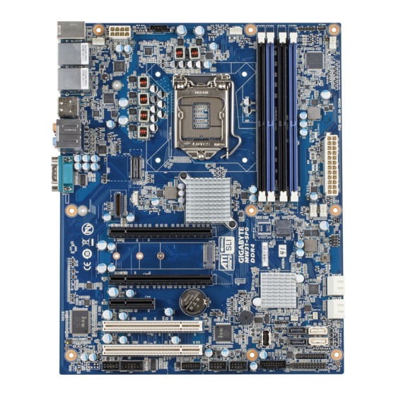
MW31-SP0 Quick Reference Guide/ 快速测试参考指南
1
2
3
4
5
6
52
51
12
13
14
15
18
17
16
CPU/System FAN/
4
1
No.
Pin Define
1
GND
4
2
+12V
No.
Pin Define
3
Sense
1
GND
1
4
Speed Control
2
GND
3
GND
1
4
GND
4
PMBUS
5
+12V
6
+12V
7
+12V
No.
Pin Define
5
8
+12V
1
PMBus Clock
2
PMBus Data
3
PMBus Alert
4
GND
1
5
3.3V Sense
HDD Back Plane Board Header/
硬盤背板排針
No.
Pin Define
No.
Pin Define
1 2
1
No Connect
2
No Connect
3
No Connect
4
FAN_SGP_GLD
5
No Connect
6
GND
7
Key Pin
8
Reset
9
GND
10
BP_LED_A_N
11
BP_LED_G_N
12
GND
13
NC
14
NC
15
GND
16
SMB_BP_DATA
17
GND
18
SMB_BP_CLK
19
P_3V3_AUX
20
No Connect
25 26
21
P_3V3_AUX
22
No Connect
23
GND
24
Key Pin
25
BP_PRESENSE
26
GND
Front Audio Connector/ 前置音频
可信平台模块
Pin Define
No.
Pin Define
Clock
1
MIC2_L
P_3V3_AUX
2
GND
LPC_RST
1
2
3
MC2_R
P3V3
4
P3V3
LPC_LAD0
5
LINE2_R
IRQ_SERIAL
6
MIC2_JD
LPC_LAD1
7
F_Audio_Sense
9
10
No Connect
8
No Pin
LPC_LAD2
9
LINE2_L
No Pin
10
LINE2_JD
LPC_LAD3
GND
LPC_FRAME_N
GND
S/PDIF In/Out Header
S/PDIF In
No.
Pin Define
No.
Pin Define
1
P_5V_AUX
1
6
NDSR-
2
SPDIF-IN
7
NRTS-
3
GND
8
NCTS-
S/PDIF Out
No.
Pin Define
9
NRI-
1
SPDIF-OUT
1
10
No Pin
2
GND
No.
Code
Description
1
COM1
Serial port
2
HD_AUDIO
Audio connectors
3
DP_HDMI
Display port port (top) / HDMI port (bottom)
7
4
USB_LAN1
LAN port #1 (top) / USB 3.0 ports (bottom)
5
USB_LAN2
LAN port #2 (top) / USB 3.0 ports (bottom)
6
PS2_USB2
PS/2 connector (top)/USB 2.0 ports (buttom)
7
SYS_FAN0
System fan connector#0
8
P2
8 pin power connector (for CPU)
8
9
PMBUS
PMBus connector
10
CPU0
Intel LGA1151 Socket H4
11
CPU0_FAN
CPU fan connector
12
DIMM_P0_A0
Channel 1 slot 0
13
DIMM_P0_A1
Channel 1 slot 1
9
14
DIMM_P0_B0
Channel 2 slot 0
15
DIMM_P0_B1
Channel 2 slot 1
16
SYS_FAN1
System fan connector#1
17
P1
24 pin main power connector
18
SYS_FAN2
System fan connector#2
19
SYS_FAN3
System fan connector#3
10
20
SATA_SGP1
SATA SGPIO header
21
SATA4_5
SATA 3 6Gb/s connectors
22
SATA6_7
SATA 3 6Gb/s connectors
23
SATA0/SATA1
SATA 3 6Gb/s connectors (Supports SATA DOM)
24
SATA2/SATA3
SATA 3 6Gb/s connectors
11
25
SATA_DOM1
SATA port 1 DOM power connector
26
SATA_DOM0
SATA port 0 DOM power connector
1
4
4
5
2
3
3
6
No.
Desription
1
PS/2 Keyboard/Mouse Port
2
USB 2.0 port
3
USB 3.0 port
风扇
4
GbE Eternet LAN port
5
Display port
6
HDMI port
7
Center/Subwoofer Speaker Out Jack (Orange)
Installing CPU/ 安装 CPU
USB 3.0 Header
No.
Pin Define
1
Power
2
IntA_P1_SSRX-
3
IntA_P1_SSRX+
4
GND
20
1
5
IntA_P1_SSTX-
6
IntA_P1_SSTX+
7
GND
8
IntA_P1_D-
9
IntA_P1_D+
10
NC
11
10
11
IntA_P2_D+
12
IntA_P2_D-
13
GND
14
IntA_P2_SSTX+
15
IntA_P2_SSTX-
16
GND
17
IntA_P2_SSRX+
18
IntA_P2_SSRX-
19
Power
20
No Pin
USB 2.0 Header
1
2
No.
Pin Define
No.
Pin Define
6
USB DY+
1
Power (5V)
2
Power (5V)
7
GND
3
USB DX-
8
GND
4
USB DY-
9
No Pin
5
USB DX+
10
No Connect
9
10
No.
Code
Description
27
BIOS_RCVR
BIOS recovery jumper
28
CASE_OPEN
Case open intrusion alert header
29
ME_RCVR
ME recovry jumper
30
USB_A1
Type A USB 2.0 connector
31
BP_1
HDD back plane board header
32
FP_1
Front panel header
33
F_USB3
USB 3.0 header
34
F_USB2
USB 2.0 header
35
BIOS_PWD
Clearing Supervisor Password jumper
36
F_USB1
USB 2.0 header
37
TPM
TPM module connector
38
COM2
Serial port cable connector
39
F_AUDIO
Front audio connector
40
PCI_1
PCI 32/33MHz slot
41
PCI_2
PCI 32/33MHz slot
42
PCIE_1
PCI Express x4 slot
43
BAT
Battery socket
44
CLR_CMOS
Clear CMOS jumper
45
ME_UPDATE
ME update jumper
46
PCIE_2
PCI Express x16 slot
47
M2_MKEY
M.2 slot (Dimension: 2280)
48
PCIE_3
PCI Express x16 slot
49
MEZZ_1
Proprietary PCI Express x4 slot for Mezzanine Card
50
SPDIF_IN
S/PDIF in header
51
TBT
Thunderbolt add-on card connector
52
SPDIF_OUT
S/PDIF out header
Rear I/O Connector/ 后面板接口
7
10
The HDMI connector is HDCP compliant and supports Dolby True HD and DTS HD
Master Audio formats. It also supports up to 192KHz/24bit 8-channel LPCM audio
8
11
13
output. You can use this port to connect your HDMI-supported monitor. The
maximum supported resolution is 4096x2160@24Hz or 2560x1600@60Hz, but the
9
12
actual resolutions supported are dependent on the monitor being used.
No.
Desription
8
Rear Speaker Out Jack (Black)
Speed LED
Link/Activity
9
Optical S/PDIF Out Connector
10
Line In Jack (Blue)
11
Line Out Jack (Green)
12
Mic In Jack (Pink)
13
Serial port
Memory Population Configuration/ 安装内存
Type
UDIMM
Unbuffered
DDR4 ECC
UDIMM
Unbuffered
DDR4 non-ECC
All channels in system run at the fastest common frequency.
Mixing ECC and non-ECC UDIMMs anywhere on the platform is not supported.
1 and 2 DPC is supported at 2133MHz.
所有通道模式以最快的频率速度运行。
此主板不支持ECC与非ECC内存模组混合使用。
1
2 DPC
2133MHz
与
均支持
速度。
Jumper Settings/ 跳线设置
1
5
2
3
4
Thunderbolt Add-On
Case Open Intrusion Header
Card Header
1
5
Open: Normal operation.
No.
Pin Define
1
GPIOA
2
GPIOB
Closed: Active chassis intrustion alert.
3
SLP_S3
4
SLP_S5
5
GND
4
10/100/1000 LAN LED:
State
Description
LED
Yellow On
1Gbps data rate
Green On
100Mbps data rate
Off
10Mbps data rate
Speed (MT/s);
Slot Per Channel (SPC) and
Ranks Per
Supported
DIMM Per Channel (DPC)
DIMM and
Voltage
Data Width
2 Slot Per Channel
1DPC
2DPC
SR
1.2V
2133
2133
DR
1.2V
2133
2133
No.
Desription
1
Clear CMOS Jumper
1-2 Close: Normal operation (Default setting)
2-3 Close: Clear CMOS data.
2
ME Update Jumper
1-2 Close: Normal operation (Default setting)
2-3 Close: ME update mode.
3
BIOS Recovery Jumper
1-2 Close: Normal operation. (Default setting)
2-3 Close: BIOS recovery mode.
4
ME Recovery Jumper
1-2 Close: Normal operation. (Default setting)
2-3 Close: ME recovery mode.
5
Clearing Supervisor Password Jumper
1-2 Close: Normal operation. (Default setting)
2-3 Close: Skip supervisor password.
NVidia SLI – System BIOS setting
To get best SLI performance, it is recommended
by NVidia to disable VT-d
Please follow below instructions to disable VT-d
function.
1. Press "DEL" to enter BIOS setup menu
2. Select Chipset > VT-d [Enabled] > VT-d
[Disabled]
P/N:12QM1-MW31S0-00R
Advertisement

Subscribe to Our Youtube Channel
Related Manuals for Gigabyte MW31-SP0


Summary of Contents for Gigabyte MW31-SP0
- Page 1 MW31-SP0 Quick Reference Guide/ 快速测试参考指南 49 50 Code Description Code Description COM1 Serial port BIOS_RCVR BIOS recovery jumper HD_AUDIO Audio connectors CASE_OPEN Case open intrusion alert header ME_RCVR ME recovry jumper DP_HDMI Display port port (top) / HDMI port (bottom) USB_LAN1 LAN port #1 (top) / USB 3.0 ports (bottom)
- Page 2 Restriction of Hazardous Substances (RoHS) Directive Statement GIGABYTE products have not intended to add and safe from hazardous substances (Cd, Pb, Hg, Cr+6, PBDE and PBB). The parts and components have been carefully selected to meet RoHS requirement. Moreover, we at GIGABYTE are continuing our efforts to develop products that do not use internationally banned toxic chemicals.
Need help?
Do you have a question about the MW31-SP0 and is the answer not in the manual?
Questions and answers