Table of Contents
Advertisement
Quick Links
WARNINGS AND CAUTIONS
• TO AVOID FIRE, SHOCK, OR DEATH; TURN OFF POWER at circuit breaker or fuse
and test that power is off before wiring!
• If you are unsure about any part of these instructions, consult an electrician.
• SAVE THESE INSTRUCTIONS.
SPECIFICATIONS
• Mains side supply voltage: 220-240V~ 50Hz
• Minimum load: 40W @ 230V~
• Maximum load: 400W @ 230V~
• Load types:
220V Incandescent
220V Halogen
Low voltage electronic transformers suitable for trailing edge dimming
INSTALLATION
• The dimmer unit should only be installed by a suitably qualified person
• This dimmer is not designed for use with fluorescent, compact fluorescent, non-dimmable electronic low voltage transformers, ceiling fans, or any appliances
• Dimmer units should be installed in a suitable distribution box fitted with 35mm din rail
• Ensure that the mains power has been switched off before commencing installation
• All mains wiring should be done in accordance with local authority wiring regulations
• Leave a space of 1 din rail module (approx. 17mm) between dimmer units
• A safe isolation distance should be kept between all mains wiring and the Bus network cable
• Always Isolate the dimmer from the mains supply before performing a Megger test on the electrical installation
• See the Omni-Bus Network Installation Guide for more information on the Bus network wiring
SETUP
• To link an Omni-Bus Wall Switch button to the dimmer without using the OMNIBUS installation software:
• Enter program mode by pressing and holding the dimmer pushbutton until the LED starts flashing amber
• Press and hold the wall switch button until the wall switch LED flashes at a faster rate
• Press and release the dimmer pushbutton to exit program mode
• Setup from OMNIBUS installation software:
• Enter the dimmer unit setup by double clicking on the device in the device list after a LIST DEVICES
• Use the Setup Tab to change the following device parameters:
• Min Level: Set minimum light level
• Max Level: Set maximum light level
• Default Soft Off/On Rate: Set the rate at which the light will switch on
• Dimming Curve: Set the dimming curve and minimum/maximum offset according to the load type
connected to the dimmer output (leave on default settings for incandescent and halogen lamps)
• Use the Links Tab to link input devices (wall switches and remote controls) to the dimmer device
OPERATION
• Press and release the unit pushbutton or external pushbutton to toggle output
• Press and hold pushbutton to dim light up or down
• Operation from an Omni-Bus Wall Switch:
• Press and release wall switch button to toggle output
• Press and hold wall switch button to dim light up or down
• The dimmer will automatically shut down (output turned off) when a fault condition is detected (see Status LED)
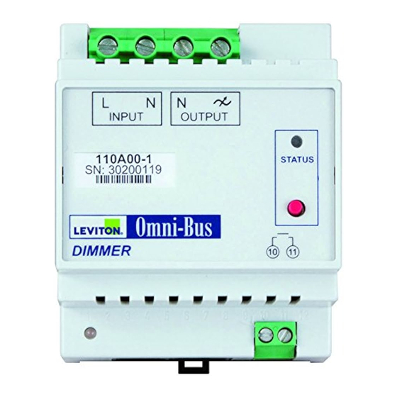
STATUS LED
• Constant Green: Output switched OFF
• Constant Red: Output switched ON
• Flashing red: Indicates fault condition
• 1 Flash: 220-240V~ supply not present
• 2 Flashes: Load short circuit condition detected
• 3 Flashes: Overload
• 4 Flashes: Incompatible load type
• 5 Flashes: Over temperature error
• 6 Flashes: Zero crossing error
• Flashing amber: Program mode active
FOR CANADA ONLY
For warranty information and/or product returns, residents of Canada should contact Leviton in writing at Leviton Manufacturing of Canada Ltd to the attention of the Quality
Assurance Department, 165 Hymus Blvd, Pointe-Claire (Quebec), Canada H9R 1E9 or by telephone at 1 800 405-5320.
Leviton warrants to the original consumer purchaser and not for the benefit of anyone else that products manufactured by Leviton under the Leviton brand name ("Product") will be free
from defects in material and workmanship for the time periods indicated below, whichever is shorter: • OmniPro II and Lumina Pro: three (3) years from installation or 42 months from
manufacture date. • OmniLT, Omni IIe, and Lumina: two (2) years from installation or 30 months from manufacture date. • Thermostats, Accessories: two (2) years from installation or
30 months from manufacture date. • Batteries: Rechargeable batteries in products are warranted for ninety (90) days from date of purchase. Note: Primary (non-rechargeable) batteries
shipped in products are not warranted. Products with Windows
at no charge, provided that the product has been used as originally intended. Installation of non-Leviton software or modification of the operating system voids this warranty. Leviton's
obligation under this Limited Warranty is limited to the repair or replacement, at Leviton's option, of Product that fails due to defect in material or workmanship. Leviton reserves the
right to replace product under this Limited Warranty with new or remanufactured product. Leviton will not be responsible for labor costs of removal or reinstallation of Product.
The repaired or replaced product is then warranted under the terms of this Limited Warranty for the remainder of the Limited Warranty time period or ninety (90) days, whichever
is longer. This Limited Warranty does not cover PC-based software products. Leviton is not responsible for conditions or applications beyond Leviton's control. Leviton is
not responsible for issues related to improper installation, including failure to follow written Installation and operation instructions, normal wear and tear, catastrophe,
fault or negligence of the user or other problems external to the Product. To view complete warranty and instructions for returning product, please visit us at www.leviton.com.
LEVITON OMNI-BUS DIMMER DIN RAIL
CAT. NO.
Installation Instructions and User's Guide
INSTALLATION
LEVITON LIMITED WARRANTY
Operating Systems: During the warranty period, Leviton will restore corrupted operating systems to factory default
®
110A00-1
WARNINGS AND CAUTIONS
• To be installed and/or used in accordance with appropriate electrical codes and
regulations.
• Use this device with copper or copper-clad wire only.
• For indoor use only.
• Bus side supply voltage: 15-24VDC (via bus network cable)
• Bus side supply current: 20mA maximum
• Memory capacity (linked devices): 32
• Ambient Temperature: 0 – 40 ºC (32 – 104 ºF)
• Ingress Protection: IP20
• Dimensions: 70mm (width) x 58mm (height) x 86mm
PK-93500-10-A0-8A
(110I00-1)
ENGLISH
Advertisement
Table of Contents

Subscribe to Our Youtube Channel
Related Manuals for Leviton 110A00-1


Summary of Contents for Leviton 110A00-1
- Page 1 LEVITON LIMITED WARRANTY Leviton warrants to the original consumer purchaser and not for the benefit of anyone else that products manufactured by Leviton under the Leviton brand name (“Product”) will be free from defects in material and workmanship for the time periods indicated below, whichever is shorter: • OmniPro II and Lumina Pro: three (3) years from installation or 42 months from manufacture date.
- Page 2 Copyright and Trademark Information This document and all its contents herein are subject to and protected by international copyright and other intellectual property rights and are the property of Leviton Manufacturing Co., Inc, its subsidiaries, affiliates and/or licensors. © 2013 Leviton Manufacturing Co., Inc. All rights reserved.
Need help?
Do you have a question about the 110A00-1 and is the answer not in the manual?
Questions and answers