Table of Contents
Advertisement
Quick Links
WARNINGS AND CAUTIONS
• Read and understand all instructions. Follow all warnings and instructions marked on the product.
• Do not use this product near water - e.g., near a tub, wash basin, kitchen sink or laundry tub, in a
wet basement, or near a swimming pool.
• Never push objects of any kind into this product through openings, as they may touch dangerous
voltages.
• SAVE THESE INSTRUCTIONS.
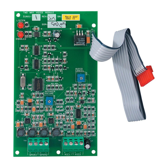
DESCRIPTION
The Model 10A11-1, Rev C Two-Way Audio/Voice Alarm Module allows two-way communication with a central station after an alarm, paging and listening from an on-premises or
remote phone, annunciation of alarm and zone by voice, and voice messaging. The Model 10A11-1, Rev C also provides a line-level audio output that can be tied into an amplifier or
whole home audio system, and a page output that is activated whenever the Model 10A11-1, Rev C generates audio output.
FEATURES
• Two independent audio amplifiers
• Two microphone inputs
• Line-level audio output (3.5mm jack)
• Page output (contact closure)
• Automatic gain control (AGC) for talk and listen
• Two-way or listen-only operation
• Control via standard Touch-Tone phone
• Connects to Leviton Speaker/Microphone Modules and/or Omni Consoles
and Lumina Keypads with Built-in Speaker/Microphone
• Connects to Hi-Fi by Leviton and other whole home audio distribution systems
for announcing voice messages and paging
INSTALLATION
Connect 8-ohm speaker(s) and two-wire electret microphone(s) to the Model 10A11-1, Rev C - See Figure 1. Leviton Model 28A00-1 (Surface) or Model 28A00-2 (Flush) Speaker/
Microphone Modules and/or Model 33A00-4 Omni Consoles and Model 33A00-20 Lumina Keypads with Built-in Speaker/Microphone can be used. NOTE: Do not mount speakers,
microphones, 28A00 modules, 33A00-4 consoles, or 33A00-20 keypads near any device that may produce noise (fans, air conditioning units, audio speakers, etc.).
Microphones:
Microphones should be connected with 24 AWG or larger, shielded twisted pair wire. Wire length should not exceed 100 feet. Connect the cable shields and negative wires
together at the Model 10A11-1, Rev C terminal block only. Do not connect the shield on the microphone end. Additional microphones can be connected to each input in parallel.
Speakers:
Speakers should be connected with 18 AWG or larger, twisted pair wire. For wire runs that exceed 50 feet, use 16 AWG wire or larger. Wire length should not exceed 100 feet.
Additional speakers can be connected to each output in series.
Line-Level Audio Output:
A power amplifier may be connected to the line-level audio output using a 3.5mm patch cable. This is typically used to annunciate the audio output from the Model 10A11-1,
Rev C throughout a home when used with a whole home audio distribution system.
Page Output:
The page output provides a contact closure whenever the Model 10A11-1, Rev C generates audio. This is typically used to trigger the paging feature of a whole home audio
distribution system.
MOUNTING
When mounting and connecting the Model 10A11-1, Rev C, power down the controller (AC and battery). Connecting the Model 10A11-1, Rev C board, while power is still applied
to the controller, can damage the board, the controller, or both.
Mount the Model 10A11-1, Rev C to the upper right side of the enclosure using the supplied adhesive-backed resealable fasteners.
When connecting to an OmniLT, route the cable to the connector on the top of the board marked "J1". Plug the Model 10A11-1, Rev C cable into "J1" on the controller.
The red wire should be to the left of the connector (red wire to Pin 1) - See Figure 2.
Make sure that the connector is aligned with the pins on "J1".
When connecting to an Omni II, OmniPro II, Lumina, or Lumina Pro, route the cable along the top of the enclosure to the connector on the left side marked "J2". Plug the Model
10A11-1, Rev C cable into "J2" on the controller. The red wire should be to the top of the connector - See Figure 3. Make sure that the connector is aligned with the pins on "J2".
TWO-WAY AUDIO/VOICE ALARM MODULE
Installation Instructions and User's Guide
Figure 1 - Speaker/Microphone Connections
28A00-1, 28A00-2,
33A00-4 CONSOLE,
33A00-20 KEYPAD, OR
SPEAKERS / MICROPHONES
TWISTED PAIR
8 OHM
SPEAKER
TWISTED PAIR
8 OHM
SPEAKER
TWO-WIRE
ELECTRET
MICROPHONE
TWISTED PAIR
WITH SHIELD
TWO-WIRE
ELECTRET
MICROPHONE
AUDIO IN
SOURCE 6
HI-FI
PAGE
IN
HI-FI
Cat. No. 10A11-1
INSTALLATION
WARNINGS AND CAUTIONS
• Never install communications wiring or components during a lightning storm.
• Never install communications components in wet locations unless the
components are designed specifically for use in wet locations.
• Never touch uninsulated wires or terminals unless the wiring has been
disconnected at the network interface.
• Use caution when installing or modifying communications wiring or
components.
SPECIFICATIONS
DIMENSIONS:
OPERATING VOLTAGE:
OPERATING CURRENT:
SPEAKER IMPEDANCE:
AGC RANGE:
REQUIRED MICROPHONE TYPE: Condenser w/ built-in preamp
MODEL 10A11-1, REV C
TWO-WAY AUDIO/VOICE ALARM MODULE
+
SPKR1 (SPEAKER #1 OUTPUT)
-
SPKR1 (SPEAKER #1 COMMON)
+
SPKR2 (SPEAKER #2 OUTPUT)
-
SPKR2 (SPEAKER #2 COMMON)
+
MIC1 (MICROPHONE #1 INPUT)
-
MIC1 (MICROPHONE #1 COMMON)
+
MIC2 (MICROPHONE #2 INPUT)
-
MIC2 (MICROPHONE #2 COMMON)
LINE OUT (LINE-LEVEL AUDIO OUTPUT)
5.5" x 3.25"
6 to 14 VDC
500 mA maximum
8 Ω
-22 dbm to +10 dbm
PAGE OUT (PAGE OUTPUT)
PAGE OUT (PAGE OUTPUT)
DI-021-OA103-00A
AR2213
(10I11-1)
ENGLISH
Advertisement
Table of Contents

Subscribe to Our Youtube Channel
Related Manuals for Leviton 10A11-1


Summary of Contents for Leviton 10A11-1
- Page 1 When connecting to an Omni II, OmniPro II, Lumina, or Lumina Pro, route the cable along the top of the enclosure to the connector on the left side marked "J2". Plug the Model 10A11-1, Rev C cable into "J2" on the controller. The red wire should be to the top of the connector - See Figure 3. Make sure that the connector is aligned with the pins on "J2".
- Page 2 Leviton’s option, of Product that fails due to defect in material or workmanship. Leviton reserves the right to replace product under this Limited Warranty with new or remanufactured product. Leviton will not be responsible for labor costs of removal or reinstallation of Product. The repaired or replaced product is then warranted under the terms of this Limited Warranty for the remainder of the Limited Warranty time period or ninety (90) days, whichever is longer.
Need help?
Do you have a question about the 10A11-1 and is the answer not in the manual?
Questions and answers