Table of Contents
Advertisement
Quick Links
Advertisement
Table of Contents

Related Manuals for NEC MD210C3


Summary of Contents for NEC MD210C3
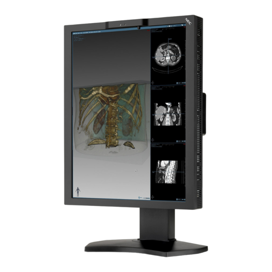
- Page 1 Medical Display MD210C2 MD210C3 MD211C2 MD211C3 INSTALLATION & MAINTENANCE GUIDE...
-
Page 2: Table Of Contents
Controls ............................English-12 Using the PICTURE MODE function ....................English-16 Quick screen QA test function ......................English-17 Advanced OSD ..........................English-18 Specifi cations - MD210C2 ......................English-23 Specifi cations - MD210C3 ......................English-24 Specifi cations - MD211C2 ......................English-25 Specifi cations - MD211C3 ......................English-26 Features ............................English-27 Troubleshooting ..........................English-28 STAND-ALONE CALIBRATION ....................English-29... - Page 3 This product can only be serviced in the country where it was purchased. Windows is a registered trademark of Microsoft Corporation. NEC is a registered trademark of NEC Corporation. ErgoDesign is a registered trademark of NEC Display Solutions, Ltd. in Austria, Benelux, Denmark, France, Germany, Italy, Norway, Spain, Sweden, U.K.
-
Page 4: Intended Use
The MD210C2/MD210C3/MD211C2/MD211C3 Color displays are intended to be used for displaying and viewing of digital images for diagnosis by trained physicians. To guarantee the display performance as specifi ed, it must only be used in conjunction with NEC approved display controllers. MD210C2/MD210C3/MD211C2/MD211C3 cannot be used for a life-support system. -
Page 5: Registration Information
Declaration Declaration of the Manufacturer Declaration of the Manufacturer Means of Conformity NEC Display Solutions Europe GmbH declares that the product listed is in conformity with the essential requirements and Device Classifi cation: Class I, non-measuring function provisions of the Council Directive 93/42/EEC, including the Applicable Rules: Annex IX, Rules 1.4 (Section 1) -
Page 6: Recommended Use
WARNING: To avoid risk of electric shock, this equipment must only be connected to a supply mains with protective earth. WARNING: No modifi cation of this equipment is allowed. WARNING: For EMC details information, please contact the NEC local representative. •... - Page 7 Get regular eye checkups. NOTE: This model is set up in the factory so that the NEC logo is briefl y displayed after the monitor is powered on. This feature can be turned on or off in the Advanced OSD.
-
Page 8: Contents
Contents Your new NEC monitor box* should contain the following: • MD210C2/MD210C3/MD211C2/MD211C3 monitor with tilt/swivel/pivot/height adjust stand • Power Cord • DVI-D cable* • DisplayPort cable • USB Cable • Quick Reference Guide • CD-ROM x 2 • Screw (x 4) (to mount the monitor to a fl exible arm (page 11)) -
Page 9: Connecting The Cables
In order to display the maximum resolution, a display controller that can output a resolution of 1200 x 1600 (in portrait mode) or 1600 x 1200 (in landscape mode) for MD210C2/MD211C2 and 1536 x 2048 (in portrait mode) or 2048 x 1536 (in landscape mode) for MD210C3/MD211C3 is needed. 1. Turn off the computer. - Page 10 4. Connect all cables to the appropriate connectors (Figure C.1). When using the USB cable, connect the B type connector to the USB upstream port on the right back side of the monitor and the A type connector to the USB 2.0 downstream port on the computer (Figure C.1a).
- Page 11 7. Slide down the cable cover (Figure D.1). 8. Connect one end of the power cord to the AC inlet on the back side of the monitor and the other end to the power outlet. NOTE: Please refer to the Caution section of this manual for proper selection of an AC power cord. Figure D.1 9.
- Page 12 Screen Rotation Before rotating, the screen must be raised to the highest level and tilt to avoid knocking the screen on the desk or pinching your fi ngers. Disconnect all cables. To raise the screen, place hands on each side of the monitor and lift up to the highest position (Figure RL.1). To rotate the screen, place hands on each side of the monitor and turn clockwise from Landscape to Portrait or counter- clockwise from Portrait to Landscape (Figure R.1).
- Page 13 Flexible Arm Installation This LCD monitor is designed for use with a fl exible arm. To prepare the monitor for alternate mounting purposes: • Follow the instructions provided by the manufacturer of the monitor mount. • To meet the safety requirements, the monitor must be mounted to an arm that supports the weight of the monitor. See pages 23-26 for details.
-
Page 14: Controls
Controls OSD (On-Screen Display) control buttons on the front of the monitor function as follows: To access the OSD menu, press the EXIT button. To change the signal input, press the SELECT button. All buttons are located at the back side of the monitor. The Key Guide appears pressing any button when not in the OSD control menu. - Page 15 SETTING OSD LANGUAGE • Set the OSD language before using OSD functions. • Use the control keys (LEFT/RIGHT or UP/DOWN or EXIT) to access the “LANGUAGE SELECTION” menu. • Press the LEFT/RIGHT or UP/DOWN buttons to select the desired OSD language. •...
- Page 16 AUTO: The preferred timing depends on the physical orientation of the monitor. Landscape orientation: 1600 x 1200 pixels, portrait orientation: 1200 x 1600 pixels for MD210C2/MD211C2. Landscape orientation: 2048 x 1536 pixels, portrait orientation: 1536 x 2048 pixels for MD210C3/MD211C3. The orientation is automatically detected by a sensor.
- Page 17 OSD LOCK OUT This control completely locks out access to all OSD control functions. When attempting to activate OSD controls while in the Lock Out mode, a screen will appear indicating the OSD controls are locked out. There are two types of OSD LOCK OUT: OSD LOCK OUT with no control: To activate the OSD Lock Out function, press SELECT, then “RIGHT”...
-
Page 18: Using The Picture Mode Function
Medical settings for endoscopic imaging view. Setting for Gamma 2.2 image. PROGRAMMABLE For Hardware Calibration settings by NEC Display Solutions QA software (some OSD settings are disabled). NOTE: A “PICTURE MODE IS LOCKED” warning message appears, when PICTURE MODE is locked out. -
Page 19: Quick Screen Qa Test Function
Quick screen QA test function The quick screen QA test allows the monitor to display an internal test pattern similar to AAPM TG18-QC, without using an external signal source. A quick overall visual evaluation as well as an inspection of the gray levels according to DICOM is available with this built-in method. -
Page 20: Advanced Osd
PROGRAMMABLE: The Gamma correction (Display Function) can be changed by using the NEC Display Solutions GammaCompMD QA software. For DICOM calibration according to DICOM Part 14. This setting can be selected only by using the NEC Display Solutions software when PICTURE MODE is set to PROGRAMMABLE. Not selectable on the Advanced menu. - Page 21 Adjusts color gamut. When the selected settings are outside of the LCD gamut, the GREEN indicator on the OSD will turn magenta. BLUE UNIFORMITY This function electronically compensates the slight variations in the white uniformity level that may occur across the display area of the screen. These variations are a characteristic of LCD panel technology.
- Page 22 Tag4 H.POSITION Controls the Horizontal Image Position within the display area of the LCD. Press “LEFT” or “RIGHT” to adjust. V.POSITION Controls the Vertical Image Position within the display area of the LCD. Press “LEFT” or “RIGHT” to adjust. H.RESOLUTION Adjusts the horizontal size by increasing or decreasing the setting.
- Page 23 BOOT LOGO* The NEC logo is briefl y displayed after the monitor is powered on. This feature can be turned on or off in the OSD. Note: If the “EXIT” button is kept pressed while NEC logo is displayed, the BOOT LOGO menu will appear.
- Page 24 Landscape orientation: 1600x1200 pixels, portrait orientation: 1200x1600 pixels for MD210C2/MD211C2. Landscape orientation: 2048x1536 pixels, portrait orientation: 1536x2048 pixels for MD210C3/MD211C3. The orientation is automatically detected by a sensor. LANDSCAPE: The preferred timing is fi xed to landscape orientation: 1600x1200 pixels for MD210C2/MD211C2 and 2048x1536 pixels for MD210C3/MD211C3.
-
Page 25: Specifi Cations - Md210C2
1280 x 960* at 60 Hz 1280 x 1024* at 60 Hz to 85 Hz 1600 x 1200 at 60 Hz........... NEC DISPLAY SOLUTIONS recommended resolution 1200 x 1600 at 60 Hz........... for optimal display performance. Active Display Area Landscape: Horiz.: 432.0 mm/17.0 inches... -
Page 26: Specifi Cations - Md210C3
1920 x 1200* at 60 Hz to 85 Hz 2048 x 1536 at 30 Hz to 60 Hz 2048 x 1536 at 60 Hz........... NEC DISPLAY SOLUTIONS recommended resolution 1536 x 2048 at 60 Hz........... for optimal display performance. Active Display Area Landscape: Horiz.:... -
Page 27: Specifi Cations - Md211C2
1280 x 960* at 60 Hz 1280 x 1024* at 60 Hz to 85 Hz 1600 x 1200 at 60 Hz........... NEC DISPLAY SOLUTIONS recommended resolution 1200 x 1600 at 60 Hz........... for optimal display performance. Active Display Area Landscape: Horiz.: 432.0 mm/17.0 inches... -
Page 28: Specifi Cations - Md211C3
1920 x 1200* at 60 Hz to 85 Hz 2048 x 1536 at 30 Hz to 60 Hz 2048 x 1536 at 60 Hz........... NEC DISPLAY SOLUTIONS recommended resolution 1536 x 2048 at 60 Hz........... for optimal display performance. Active Display Area Landscape: Horiz.:... -
Page 29: Features
Features DisplayPort: DisplayPort is designed to be the future-ready, scalable solution for high performance digital display connectivity. It enables the highest resolutions, the fastest refresh rates and deepest color depths over standard cables. DVI-D: The digital-only subset of DVI ratifi ed by the Digital Display Working Group (DDWG) for digital connections between computers and displays. -
Page 30: Troubleshooting
NOTE: As with all personal display devices, NEC DISPLAY SOLUTIONS recommends using a moving screen saver at regular intervals whenever the screen is idle or turning off the monitor when not in use. -
Page 31: Stand-Alone Calibration
STAND-ALONE CALIBRATION Stand alone calibration can recalibrate the display without using a computer by the integrated front sensor or connecting an external sensor. There are 5 functions in STAND-ALONE CALIBRATION. • Self Calibration: Calibrates the integrated front sensor based on the USB color sensor. Alternatively, manually adjust the integrated front sensor with an external near range color analyzer reference, which is traceable to a primary standards laboratory. -
Page 32: Self Calibration
Self Calibration Calibrates the integrated front sensor based on the USB color sensor. Or to manually adjust the integrated front sensor with an external near range color analyzer reference, which is traceable to a primary standards laboratory. All PICTURE MODES are updated when Self Calibration is performed. -
Page 33: Copy Calibration
Display A – SOURCE display of white point and luminance to copy. Display B – MD210C2/MD210C3/MD211C2/MD211C3 which performs a copy. 1. To show the CALIBRATION menu, plug-in the USB color sensor to the sensor port (Figure C.1) or select the STAND ALONE CALIBRATION in the advanced menu (page 22). -
Page 34: Gamma Adjust
Gamma Adjust By using the integrated front sensor, Gamma Adjust recalibrates the LCD gamma. Gamma Adjust is recommended if MAX GSDF ERROR exceeds the medical standards. All PICTURE MODES are updated when Gamma Adjust is performed. 1. To show the CALIBRATION menu, select the STAND ALONE CALIBRATION in the advanced menu (page 29). 2. -
Page 35: Dicom Measurement
DICOM Measurement DICOM PART14 can be performed by using the integrated front sensor. 1. To show the CALIBRATION menu, select the STAND ALONE CALIBRATION in the advanced menu (page 29). 2. Use “LEFT” or “RIGHT” to select DICOM MEASURE in the MODE selection (Figure D.1). 3. - Page 36 5. Input the value measured at 1, and press SELECT (Figure AS.3). When not having measured, press SELECT without changing the value. 6. After the CALIBRATION SUCCEEDED message appears (Figure AS.4), press SELECT. You can set DATE and TIME by using control keys, and press SELECT. 7.
-
Page 37: Manufacturer's Recycling And Energy Information
Dedicated recycling sites ensure that environmentally harmful components are properly handled and securely disposed. To ensure the best recycling of our products, NEC DISPLAY SOLUTIONS offers a variety of recycling procedures and gives advice on how to handle the product in an environmentally sensitive way, once it has reached the end of its life.
Need help?
Do you have a question about the MD210C3 and is the answer not in the manual?
Questions and answers