Table of Contents
Advertisement
Quick Links
INSTALLATION MANUAL
AIR
CONDITIONER
Please read this installation manual completely before installing the product.
Installation work must be performed in accordance with the national wiring
standards by authorized personnel only.
Please retain this installation manual for future reference after reading it thoroughly.
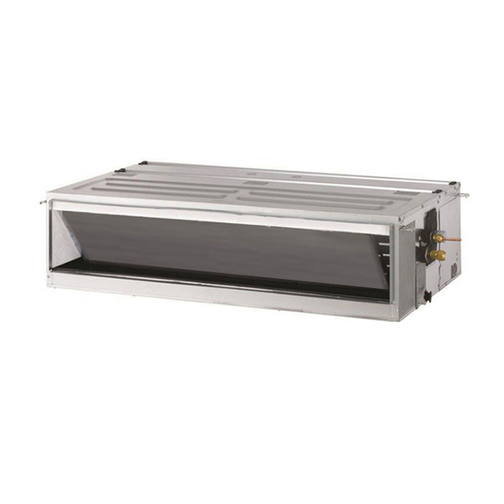
Ceiling Concealed Duct
ABNQ36GM3A4, ABQ48GM3A4
ZBNQ18GM1A0, ZBNQ24GM1A0
ZBNQ36GM3A0, ZBNQ36LM3A0
ZBNQ48GM3A0, ZBNQ48LM3A0, ZBNQ60GM3A0
MFL67939906
Rev.05_062022
Copyright © 2014 - 2022 LG Electronics Inc. All Rights Reserved.
www.lg.com
Advertisement
Table of Contents

Related Manuals for LG ABQ48GM3A4


Summary of Contents for LG ABQ48GM3A4
- Page 1 Please retain this installation manual for future reference after reading it thoroughly. Ceiling Concealed Duct ABNQ36GM3A4, ABQ48GM3A4 ZBNQ18GM1A0, ZBNQ24GM1A0 ZBNQ36GM3A0, ZBNQ36LM3A0 ZBNQ48GM3A0, ZBNQ48LM3A0, ZBNQ60GM3A0 www.lg.com MFL67939906 Rev.05_062022 Copyright © 2014 - 2022 LG Electronics Inc. All Rights Reserved.
- Page 2 TIPS FOR SAVING ENERGY TIPS FOR SAVING ENERGY Here are some tips that will help you minimize the power consumption when you use the air conditioner. You can use your air conditioner more efficiently by referring to the instructions below: •...
-
Page 3: Safety Instructions
SAFETY INSTRUCTIONS SAFETY INSTRUCTIONS The following symbols are displayed on indoor and outdoor units. Read the precautions in this manual This appliance is filled with carefully before operating the unit. flammable refrigerant (for R32) This symbol indicates that a service This symbol indicates that the personnel should be handling this Operation Manual should be read... - Page 4 SAFETY INSTRUCTIONS • For installation of the product, always contact the service center or a professional installation agency. - Otherwise, it may cause a fire, electrical shock, explosion or injury. • Securely attach the electrical part cover to the indoor unit and the service panel to the outdoor unit.
- Page 5 SAFETY INSTRUCTIONS • Do not allow water to run into electrical parts. - Otherwise, it may cause the failure of machine or electrical shock. • Hold the plug by the head when taking it out. - It may cause electric shock and damage. •...
- Page 6 SAFETY INSTRUCTIONS • Refrigerant tubing shall be protected or enclosed to avoid damage. (for R32) • Flexible refrigerant connectors (such as connecting lines between the indoor and outdoor unit) that may be displaced during normal operations shall be protected against mechanical damage. (for R32) •...
-
Page 7: Table Of Contents
TABLE OF CONTENTS TABLE OF CONTENTS TIPS FOR SAVING ENERGY SAFETY INSTRUCTIONS INTRODUCTION Features INSTALLATION OF INDOOR Selection of the best location Ceiling dimension and hanging bolt location Wiring Connection Indoor Unit Drain Piping Drain test Heat insulation REMOTE CONTROLLER INSTALLATION Group Control OPTIONAL OPERATION Installer Setting - Test Run Mode... -
Page 8: Introduction
INTRODUCTION INTRODUCTION Features Air inlet vents Air outlet vents Remote Controller Washer for hanging Clamp Insulation for Name bracket (Tie Wrap) fitting Quantity 8 EA 4 EA 1 set for gas pipe Shape for liquid pipe • Screws for fixing panels are attached to decoration panel. -
Page 9: Installation Of Indoor
INSTALLATION OF INDOOR INSTALLATION OF INDOOR Selection of the best location Ceiling dimension and hanging bolt location Install the air conditioner in the location that satisfies the following conditions. Install the unit above the ceiling correctly. - The place shall easily bear a load exceeding four times the indoor unit’s weight. - Page 10 INSTALLATION OF INDOOR Select and mark the position for CASE 2 fixing bolts - Install the unit leaning to a drainage hole side - Drill the hole for set anchor on the face of as a figure for easy water drainage. ceiling.
- Page 11 INSTALLATION OF INDOOR CAUTION - Upward routing not allowed • Install declination of the indoor unit is very important for the drain of the duct type air conditioner. • Minimum thickness of the insulation for the connecting pipe shall be 5 mm. •...
- Page 12 INSTALLATION OF INDOOR Minimum floor area(for R32) - The appliance shall be installed, operated and stored in a room with a floor area larger than the minimum area. - Use the graph of table to determine the minimum area. Amin (m Floor standing Wall mounted Ceiling mounted...
-
Page 13: Wiring Connection
INSTALLATION OF INDOOR CAUTION Wiring Connection • Open the control box cover and connect the The connecting wiring connected to the Remote controller wiring and Indoor power indoor and outdoor unit should be complied wires. with the following specifications (This •... - Page 14 INSTALLATION OF INDOOR CAUTION The Power cord connected to the unit should be selected according to the following specifications. Precautions when laying power wiring Use round pressure terminals for connections to the power terminal block. Power wiring Round pressure terminal When none are available, follow the instructions below.
-
Page 15: Indoor Unit Drain Piping
INSTALLATION OF INDOOR Indoor Unit Drain Piping Drain test - Drain piping must have down-slope (1/50 to - Connect the main drain pipe to the exterior 1/100): be sure not to provide up-and-down and leave it provisionally until the test comes slope to prevent reversal flow. -
Page 16: Heat Insulation
INSTALLATION OF INDOOR Heat insulation Use the heat insulation material for the refrigerant piping which has an excellent heat- resistance (over 120 °C). Precautions in high humidity circumstance: This air conditioner has been tested according to the "KS Standard Conditions with Mist" and confirmed that there is not any default. -
Page 17: Remote Controller Installation
REMOTE CONTROLLER INSTALLATION REMOTE CONTROLLER INSTALLATION Please fix tightly using provided screw Can set up Wired remote controller cable after placing remote controller setup board into three directions. on the place where you like to setup. - Setup direction: the surface of wall - Please set it up not to bend because poor reclamation, upper, right setup could take place if setup board... -
Page 18: Group Control
REMOTE CONTROLLER INSTALLATION CAUTION Please connect indoor unit and remote controller using connection cable. When installing the wired remote controller, do not bury it in the wall. (It can cause Please check if connector damage in the temperature sensor.) is normally connected. Do not install the cable to be 50 m or above. - Page 19 REMOTE CONTROLLER INSTALLATION - For ceiling type cassette and duct When installing more than 2 wired remote product group, change the switch setting controllers to one air conditioner, please of the indoor PCB. connect as the right picture. - When installing more than 2 units of wired remote controller to one air - No.
-
Page 20: Optional Operation
OPTIONAL OPERATION OPTIONAL OPERATION Installer Setting - Test Run Mode After installing the product, you must run a Test Run mode. For details related to this operation, refer to the product manual. OPER When pressing the button and MODE button simultaneously for more than 3 seconds, the system will be entered into the installer setting mode. -
Page 21: Installer Setting - Setting Address Of Central Control
OPTIONAL OPERATION Installer Setting - Setting Address of Central Control It's the function to use for connecting central control. Please refer to central controller manual for the details OPER When pressing the button and MODE button simultaneously for more than 3 seconds, the system will be entered into the installer setting mode. -
Page 22: Installer Setting - Thermistor
OPTIONAL OPERATION Installer Setting - Thermistor This is the function to select the temperature sensor to judge the room temperature. OPER When pressing the button and MODE button simultaneously for more than 3 seconds, the system will be entered into the installer setting mode. - After entering into the installer setting mode, select the thermistor sensor setting code value by pressing the... -
Page 23: Installer Setting - Remote Controller Master/Slave Setup
OPTIONAL OPERATION Installer Setting - Remote Controller Master/Slave Setup It is a function for settings in group control, or 2-remote controller control. OPER When pressing the button and MODE button simultaneously for more than 3 seconds, the system will be entered into the installer setting mode. -
Page 24: Installer Setting - Celsius / Fahrenheit Switching
OPTIONAL OPERATION Installer Setting - Celsius / Fahrenheit Switching This function is used for switching the display between Celsius and Fahrenheit. (Optimized only for U.S.A) OPER When pressing the button and MODE button simultaneously for more than 3 seconds, the system will be entered into the installer setting mode. -
Page 25: Installer Setting - E.s.p
OPTIONAL OPERATION Installer Setting - E.S.P. This is the function that decides the strength of the wind for each wind level and because this function is to make the installation easier. - If you set ESP incorrectly, the air conditioner may malfunction. - This setting must be carried out by a certificated-technician. -
Page 26: Installer Setting - Static Pressure Step Setting
OPTIONAL OPERATION Installer Setting - Static Pressure Step Setting This function is applied to only duct type. Setting this in other cases will cause malfunction. This function is only available on some products. This is the function that static pressure of the product is divided in 11 steps for setting. OPER When pressing the button and... - Page 27 OPTIONAL OPERATION [Table. 1] ABNQ**GM1A2(** : 12) Static Pressure[mmAq(Pa)] 2(20) 2.5(25) 3(29) 4(39) 6(59) 8(78) 10(98) 12(118) 13(127) 14(137) 15(147) Step Setting Value 32:01 32:02 32:03 32:04 32:05 32:06 32:07 32:08 32:09 32:10 32:11 HIGH 16.5 14.5 ABNQ**GM1A2(** : 24) Static Pressure[mmAq(Pa)] 2(20) 2.5(25)
- Page 28 OPTIONAL OPERATION ABNQ**GM3A2(** : 54) Static Pressure [mmAq(Pa)] 4(40) 5(50) 6(59) 7(69) 8(78) 9(88) 10(98) 11(108) 12(118) 13(127) 14(137) Step Setting Value 32:01 32:02 32:03 32:04 32:05 32:06 32:07 32:08 32:09 32:10 32:11 HIGH ABNQ**GM3A4(** : 36) Static Pressure[mmAq(Pa)] 2.5(25) 3(29) 4(39) 5(49)
- Page 29 OPTIONAL OPERATION [Table. 1] ZBNQ18GM1A0 Static Pressure[mmAq(Pa)] 2(20) 2.5(25) 3(29) 4(39) 6(59) 8(78) 10(98) 12(118) 13(127) 14(137) 15(147) Step Setting Value 32:01 32:02 32:03 32:04 32:05 32:06 32:07 32:08 32:09 32:10 32:11 HIGH 16.5 14.5 ZBNQ24GM1A0 Static Pressure[mmAq(Pa)] 2(20) 2.5(25) 3(29) 4(39) 6(59)
- Page 30 OPTIONAL OPERATION NOTE 1. Be sure to set the value refering table 1. Unexpected set value will cause mal-function. 2. Table 1 is based at 220-240 V. According to the fluctuation of voltage, air flow rate varies. 3. Factory Set(External Static Pressure) each Model ABNQ**GM1A2(** : 18, 24) Factory set (E.S.P.) Lower Limit (E.S.P)
- Page 31 OPTIONAL OPERATION NOTE 1. Be sure to set the value refering table 1. Unexpected set value will cause mal-function. 2. Table 1 is based at 220-240 V. According to the fluctuation of voltage, air flow rate varies. 3. Factory Set(External Static Pressure) each Model ZBNQ18GM1A0 , ZBNQ24GM1A0 Factory set (E.S.P.) Lower Limit (E.S.P)
-
Page 32: Installer Setting - Auto Esp
OPTIONAL OPERATION Installer Setting - Auto ESP This function automatically sets the rotation speed of the fans corresponding to each step of rated airflow for easy installation. OPER When pressing the button and MODE button simultaneously for more than 3 seconds, the system will be entered into the installer setting mode. - Page 33 OPTIONAL OPERATION ※ The voltage can be set by setting the Auto ESP Mode to 'Manual (2)', then pressing the `Fanspeed` button. ※ While 'Auto ESP' is being set, the display on the wired remote control changes as shown below, and the wired remote control cannot be operated. ※...
- Page 34 OPTIONAL OPERATION NOTE If this function is incorrectly set especially, in case of mismatching the voltage, the air conditioner may malfunction. this function must be set by the installation specialist that holds an installation license. (please check the product type) This function is only available on some products.
-
Page 35: Dip Switch Setting
DIP SWITCH SETTING DIP SWITCH SETTING Indoor PCB Indoor PCB Indoor PCB Function Description Setting Off Setting On Default Selection of Master or Group Control Master Slave Slave Wired/Wireless remote Dry Contact Selection of Dry Contact controller Auto Mode Mode Selection of Manual or Auto operation Mode Continuous operation... - Page 37 PT.LG Electronics Indonesia Gandaria 8 Office Tower Lt. 29 BC & 31 ABCD Jl.Sultan Iskandar Muda, Kebayoran Lama Utara - Kebayoran Lama, Jakarta Selatan - DKI Jakarta Raya, Indonesia...
Need help?
Do you have a question about the ABQ48GM3A4 and is the answer not in the manual?
Questions and answers