Table of Contents
Advertisement
Quick Links
AVG-SC51T
The AVG-SC51T is a compact mini scaler
switcher with 5 video inputs (3 HDMI, 2 VGA)
and 6 audio inputs (3 HDMI audio & 2 VGA
audio; 1 MIC audio input). The VGA input
supports VGA, YPbPr and C-video, assuring
the scaler switcher is compliant with multiple
video signal types.
Features
Compliant with HDCP
Supports CEC, with commands to
enable/disable this function
Supports video source auto-switching
function
Bi-directional IR & RS232 control
Output resolutions selectable to assure
preferred output, supports various
output resolutions, such as 1920x1200,
1920x1080, 1600x1200, 1360x768,
1280x800, 1280x720, 1024x768
VGA video supports C-video, YPbPr
and VGA
Supports online software upgrades
48V phantom power to support
condenser microphone
MIC port supports balanced/unbalanced
signals.
3-level MIC input, supports condenser
microphone, dynamic microphone and
wireless microphone
Controllable via button, IR & RS232
Extensive OSD function
Advertisement
Table of Contents

Related Manuals for AVGear AVG-SC51T


Summary of Contents for AVGear AVG-SC51T
- Page 1 1280x800, 1280x720, 1024x768 VGA video supports C-video, YPbPr and VGA Supports online software upgrades The AVG-SC51T is a compact mini scaler 48V phantom power to support switcher with 5 video inputs (3 HDMI, 2 VGA) condenser microphone and 6 audio inputs (3 HDMI audio & 2 VGA MIC port supports balanced/unbalanced audio;...
- Page 2 AVG-SC51T PLEASE READ THIS PRODUCT MANUAL CAREFULLY BEFORE USING THIS PRODUCT. This manual is only for operation instruction only, and not to be used in a maintenance capacity. The functions described in this version are current as at March 2015. Any changes of functions and operational parameters will be updated in future manual versions.
- Page 3 AVG-SC51T SAFETY OPERATION GUIDE In order to guarantee the reliable operation of the equipment and safety of the user, please abide by the following procedures in installation, use and maintenance: 1. The system must be earthed properly. Please do not use two blade plugs and ensure the alternating power supply ranges from 100v to 240v and from 50Hz to 60Hz.
-
Page 4: Table Of Contents
Installation/Removal of the RS232 Control Software ...... 4.4.1 Basic Settings ................. 4.4.2 RS232 Communication Commands ..........4.4.3 Controlling the AVG-SC51T or 3rd Party Device Locally ....4.4.4 Controlling the AVG-SC51T Locally or Remotely ......4.4.5 Operations in the OSD Menu................ 4.5 Option ..................... -
Page 5: Introduction
1. Introduction 1.1. Introduction to AVG-SC51T The AVG-SC51T is a compact mini scaler switcher with 5 video inputs (3 HDMI, 2 VGA) and 6 audio inputs (3 HDMI audio & 2 VGA audio: switched following the video; 1 MIC audio input). The VGA input supports VGA, YPbPr and C-video, assuring the scaler switcher is compliant with multiple video signal types. - Page 6 AVG-SC51T 1.3. Package Contents 1 x AVG-SC51T 2 x Mounting ears (for AVG-SC51T) 1 x AVG-HD402PR 2 x Mounting ears (for AVG-HD402PR) 5 x Screws 7 x Captive screw connectors 1 x IR receiver 1 x IR emitter 2 x VGA to YPbPr cables...
-
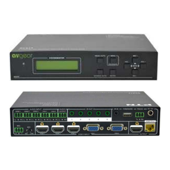
Page 7: Product Appearance
AVG-SC51T 2. Product Appearance 2.1. AVG-SC51T Front Panel ① Power indicator Illuminates red when power is on, turns green in standby mode. ② LCD screen Shows the real-time system working status ③ SOURCE/AUTO Used as the video source selection button, press to select one source, press again to select next source, switching through in turn between HDMI1, HDMI2, HDMI3, VGA1 and VGA2. - Page 8 AVG-SC51T ⑥ MENU/FWUPDATE Menu button, press it to enter into the OSD menu. Used also as the software updating button, press and hold for 7 seconds or more to enter into the software updating procedure. ⑦ VOL- Used as the volume down button.
-
Page 9: Avg-Sc51T Rear Panel
Audio output port, the audio comes from the input audio corresponding to the selected video source and is mixed with MIC audio. ③ IR OUT 5 in total, connect with IR emitters to control local source devices or AVG-SC51T remotely, switched along with the corresponding video source. ④ IR IN Connects with IR receiver (with IR carrier only), to receive IR signals sent by the IR remote or remote controller of another input/output device. - Page 10 AVG-SC51T a) MIC port Connection for a microphone b) Mic switch 3 Positions: 48V phantom power mode (connect with condenser microphone), MIC mode (connect with a dynamic microphone) and LINE mode (connect with a wireless microphone or line audio). ⑨ VIDEO INPUT Video input ports, include 3 HDMI inputs &...
-
Page 11: System Connection
SC51T with audio cable. The audio of HDMI can be embedded or external by sending the right command. Step 3. Connect a HDMI display device to HDMI output port of AVG-SC51T with HDMI cable. Step 4. Connect AVG-HD402PR to HDBaseT output port of AVG-SC51T with twisted pair. - Page 12 AVG-SC51T Step 7. Both AVG-SC51T and AVG-HD402PR have IR IN and OUT. When one model is connected with IR receiver, the other model should connect with an IR transmitter. For example: When “IR IN” of AVG-SC51T connects with an IR receiver, the IR transmitter must connect to IR OUT of AVG-HD402PR.
- Page 13 AVG-SC51T MIC input MIC input has low frequency characteristics, and wide frequency response. When switched to “MIC”, the microphone input is used for connecting with dynamic microphone. There are two different connection methods: 1. Unbalanced connection: “+” and “ ” connect to ground, and “-” connects to signal. “- ”...
-
Page 14: Application
2. Balanced connection: “+” connects to positive, “-” connects to negative and “ ” connects to ground. 3.5. Application AVG-SC51T has great application in various systems such as the IT realm, monitoring, conference rooms, big screen displays, broadcast, education, command & control centers and smart homes etc. -
Page 15: System Operations
RESO/AUTO button for 7 seconds or more to switch between auto-adjusting/ manual-adjusting mode. Note: 1. In auto-adjusting mode, AVG-SC51T will choose the resolution of the display device at the far-end as the preferred resolution. If you need to choose the resolution of local HDMI display device: Turn off the power of AVG-SC51T and disconnect the AVG-SC51T and AVG- HD402PR. - Page 16 If the last displayed signal is still available, AVG-SC51T will output the signal. If not, there will be no signal on output devices. Signal removing principle Once removing the current display signal, AVG-SC51T will detect all input signals with priority from INPUT 1 to INPUT 5.
-
Page 17: Used In Osd Menu
AVGear engineering department or from our website: www.avgear.com.au 2. Plug the USB flash disk to the AVG-SC51T USB port on its front panel. 3. Press the button “MENU” for 7 seconds or more to update the software automatically. -
Page 18: Operations Of Ir
4.2.1. IR Remote As an IR signal can be transmitted bi-directionally between AVG-SC51T and AVG- HD402PR, it is able to use the IR remote at the far-end to control AVG-SC51T or HDMI source devices (via CEC function buttons). ① Standby button Enter/ exit standby mode ②... -
Page 19: Ir Operations
1. Control of far-end device from local Control AVG-SC51T or far-end display device from local through corresponding IR remote. 2. Control local device from remote Control AVG-SC51T or local device from local through corresponding IR remote. -
Page 20: Operation Of The Cec Function
AVG-SC51T 4.3. Operation of the CEC Function AVG-SC51T supports CEC, it can be turned on/ off by sending RS232 commands or OSD menu operations. The default setting is ON. Commands pertaining to CEC: “50686%” (enable CEC) and “50687%” (disable CEC) -
Page 21: Operations Of Rs232 Control
Removal: Delete all the control software files in corresponding file path. 4.4.2. Basic Settings First to connect AVG-SC51T with all input devices and output devices needed, then to connect it with a computer which is installed with RS232 control software. Double- click the software icon to run this software. -
Page 22: Rs232 Communication Commands
AVG-SC51T Please set the parameters of COM number, baud rate, data bit, stop bit and the parity bit correctly, and then you are able to send command in the Command Sending Area. 4.4.3. RS232 Communication Commands Communication protocol: RS232 Communication Protocol... - Page 23 AVG-SC51T Command Function Feedback Example Display channel status Input Icon: enable 50644% 50645% Not display channel status Input Icon: disable 50650% Check the channel status Input Icon: xx Auto-adjust the input parameter 50606% VGA Input Auto (VGA only) 50699% Check the system version Version Vx.x.x...
- Page 24 AVG-SC51T Command Function Feedback Example Inquire Commands LINE Volume: xx (xx=0~66) Check the volume level 50630% MIC Volume: xx (xx=0~66) Input: xx (xx= HDMI1/ HDMI2/ 50631% Check the input source HDMI3/ VGA1/ VGA2/ YPbPr1/ YPbPr2/ AV1/ AV2) Resolution: xx (xx=1920×1200/ 1920×1080/ 1600×1200/ 1360...
- Page 25 4.4.4. Control AVG-SC51T or 3rd Party Device Locally Firstly, connect the RS232 port of AVG-SC51T to RS232 port of PC. Secondly, send command 50787% (serial control mode 1, factory default) via RS232 communication software.
- Page 26 4.4.5. Control the AVG-SC51T from a Local or Remote location Control AVG-SC51T locally Firstly, connect the RS232 port of AVG-SC51T to RS232 port of PC. Secondly, send command 50788% via RS232 communication software. Lastly, send the right command to control AVG-SC51T. Connect as below:...
-
Page 27: Operations In The Osd Menu
AVG-SC51T 4.5. Operations in the OSD Menu AVG-SC51T provides a powerful OSD operation menu, contains 4 parts: optional settings, image settings, audio settings and system setting etc. Press MENU button on front panel (or MENU button on IR remote/send command 50616%) to enter in OSD menu, so it is able to do some settings through the OSD menu. -
Page 28: Picture
HDMI3. Software Update (USB): Insert the USB flash disk with updating file to USB port of AVG-SC51T, to update the software through this menu. 4.5.2. Picture Including Picture Mode, Color Temperature, Aspect Ratio, Noise Reduction, Screen and Color Range. -
Page 29: Sound
AVG-SC51T Noise Reduction (not for VGA format): Includes Off, Low, Middle, High and Default. Screen (not for HDMI source): Includes Auto Adjust, Horizontal, Vertical, Size, and Phase. Color Range (not for VGA format): 0~255, use ENTER button to select the color range. - Page 30 VERSION: Displays software version 4.6. Instructions to use the VGA Converting Cable As VGA source supports YPbPr and C-video source, AVG-SC51T provides with 2 VGA converting cables to compliant with these signals. When need to select these signals as input source, please switch to channel INPUT 4 (or INPUT 5), and then set the signal type in OSD.
- Page 31 AVG-SC51T After setting, press SOURCE/AUTO button on front panel to switch to YPbPr1 or YPbPr2 source. 2. Via RS232 commands Send command 50681% (or 50684%) to switch to YPbPr1 (or YPbPr2) source. 3. Via IR remote & OSD Press MENU button on IR remote to enter in OSD, and then enter in OPTION setting menu: set “INPUT 4 Select”...
-
Page 32: Specifications
AVG-SC51T 5. Specifications Video Input Video Output 3 HDMI 1 HDMI Input Output 2 VGA 1 HDBaseT Input 3 female HDMI Output 1 female HDMI Connector 2 female VGA (15 pin) Connector 1 RJ45 HDMI, YPbPr, C-video, 1 HDMI Video Signal... - Page 33 AVG-SC51T General Temperature -10 ~ +40℃ Humidity 10% ~ 90% 8W, supply power to AVG-SC51T and AVG- Power Power HD402PR separately DC12V ± 0.5V Supply Consumption 16W, AVG-SC51T supplies power to AVG- HD402PR Dimension 220x 44x 148mm Weight 0.65Kg (W*H*D)
-
Page 34: Panel Drawing
AVG-SC51T 6. Panel Drawing... -
Page 35: Troubleshooting & Maintenance
AVG-SC51T 7. Troubleshooting & Maintenance Problems Causes Solutions Bad quality connecting Try another high quality cable cable. Output image has noise Failed or loose Re-seat the connector connection Check with oscilloscope or No signal at the input / multimeter if there is any...
Need help?
Do you have a question about the AVG-SC51T and is the answer not in the manual?
Questions and answers