Table of Contents
Advertisement
Quick Links
User Manual
The AVG-UDA24-HD70 supports switching
between two video signal and long
distribution range up to 4K 70m via CATx,
with HDMI loop out for cascading. It
supports video resolutions up to 4K@60Hz
4:4:4 8bit and all HDMI audio formats, and
down-scaling from 4K to 1080P. Also
supports Audio de-embedding, and PoC to
power the receiver.
Supports HDMI V2.0, video resolutions up
▪
to 4K@60Hz 4:4:4.
Transmission distance up to 70m for 4K
▪
and 80m for 1080p
Distributes one of two UHD/4K HDMI
▪
inputs to four CATx outputs and one HDMI
loop output.
Comprehensive EDID management
▪
Video auto-switching based on 5V or
▪
TMDS detection.
SPDIF and L/R audio outputs for audio de-
▪
embedding.
Bi-directional IR pass-through and IR
▪
cascade control.
Controllable via front panel button, IR and
▪
RS232.
12V PoC to power the receiver.
▪
Advertisement
Table of Contents

Related Manuals for AVGear AVG-UDA24-HD70


Summary of Contents for AVGear AVG-UDA24-HD70
- Page 1 ▪ inputs to four CATx outputs and one HDMI loop output. Comprehensive EDID management ▪ The AVG-UDA24-HD70 supports switching Video auto-switching based on 5V or ▪ between two video signal and long TMDS detection. distribution range up to 4K 70m via CATx, SPDIF and L/R audio outputs for audio de- ▪...
- Page 2 AVG-UDA24-HD70 PLEASE READ THIS PRODUCT MANUAL CAREFULLY BEFORE USING THIS PRODUCT. This manual is for operational use only, and not to be used for maintenance. The functions described in this version are current as at June 2020. Any changes of functions and operational parameters will be updated in future manual versions.
- Page 3 AVG-UDA24-HD70 SAFETY OPERATION GUIDE In order to guarantee the reliable operation of the equipment and safety of the user, please abide by the following procedures in installation, use and maintenance: 1. The system must be earthed properly. Please do not use two blade plugs and ensure the AC power supply ranges from 100v to 240v and from 50Hz to 60Hz.
-
Page 4: Table Of Contents
AVG-UDA24-HD70 Table of Contents 1. Product Introduction ....................1 1.1 Features ......................1 1.2 What’s in the Box ....................2 2. Technical Specification ................... 3 2.1 Switcher ......................4 2.2 Receiver ......................5 3. Panel Description ..................... 6 3.1 Switcher Front Panel ..................6 3.2 Switcher Rear Panel .................. -
Page 5: Product Introduction
AVG-UDA24-HD70 1. Product Introduction Thanks for choosing this 2x4 HDMI Switcher Kit over CATx cable. This device distributes either one of two HDMI inputs to one HDMI and four CATx outputs. It is designed with an IR loop out to cascade to more units. It supports video resolutions... -
Page 6: What's In The Box
AVG-UDA24-HD70 1.2 What’s in the Box 1x AVG-UDA24T-HD702x4 HDMI Switcher over CATx ⚫ 4x Plastic Cushions ⚫ 1x RS232 Cable (3-pin to DB9) ⚫ Switcher 1x IR Cable (3.5mm to 3.5mm, used for IR cascade) ⚫ 4x IR Receivers ⚫... -
Page 7: Technical Specification
AVG-UDA24-HD70 2. Technical Specification 2.1 Switcher Video Input (1) HDMI Input Input Connector (1) Female type A HDMI HDMI Input Resolution Up to 4K@60Hz 4:4:4 8bit Video Output (1) HDMI, (4) CAT Output Output Connector (1) Female type A HDMI; (4) RJ45... -
Page 8: Receiver
AVG-UDA24-HD70 Control (1) EDID, (1) FIRMWARE, (1) IR ALL IN, (4) IR IN, (1) IR LOOP Control port OUT, (1) IR OUT, (1) RS232 IN (1) 3-pin DIP switch, (1) USB-A, (7) 3.5mm mini jacks, (1) 3-pin Control Connector terminal block... - Page 9 AVG-UDA24-HD70 Bidirectional PoC Supported HDMI 2.0 Cable Length 4K@60Hz 4:4:4 ≤ 5m, 4K@60Hz 4:2:0 ≤ 10m, 1080p ≤ 15m Transmission Distance 4K ≤ 70 meters (230ft), 1080p ≤262 feet (80 meters) Operation Temperature -5~ +55℃ Storage Temperature -25 ~ +70℃...
-
Page 10: Panel Description
AVG-UDA24-HD70 3. Panel Description 3.1 Switcher Front Panel HDMI 1 HDMI 2 SELECT DEFAULT H.RES L.RES 1. POWER LED: Illuminates green when power is applied. ⚫ Blinks when the device is in standby mode. ⚫ Off when power is off. -
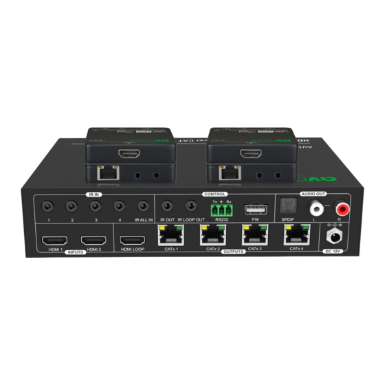
Page 11: Switcher Rear Panel
AVG-UDA24-HD70 3.2 Switcher Rear Panel 1. HDMI INPUT: Connects to HDMI source device. 2. OUTPUTS: HDMI: Type-A female HDMI port to connect local HDMI display device. ⚫ CATx 1~4: RJ45 port to connect the CATx IN port of receiver by CATx cable. It ⚫... -
Page 12: Receiver Panel
AVG-UDA24-HD70 3.3 Receiver Panel 1. DISPLAY: Type-A female HDMI port to connect HDMI display device. 2. CATx IN: RJ45 port to connect the CATx OUT port of transmitter by CATx cable. It supports 12V PoC and the receiver can be powered from the transmitter. The orange LED illuminates when there is a valid HDMI signal input. -
Page 13: System Connection
AVG-UDA24-HD70 4. System Connection 4.1 Usage Precautions Make sure all components and accessories included before installation. ⚫ System should be installed in a clean environment with proper temperature and ⚫ humidity. All of the power switches, plugs, sockets, and power cords should be insulated ⚫... -
Page 14: Source Switching
AVG-UDA24-HD70 5. Source Switching 1) Press the SELECT button to switch to next source device, and then the corresponding input LED will turn green. 2) Press and hold the SELECT button at least 3 seconds to enable auto switching mode, and it abides by the following principles: The switcher will switch to the first available active input starting at HDMI IN ⚫... -
Page 15: Ir Control
AVG-UDA24-HD70 7. IR Control The IR receivers and emitters can be connected to the system to allow IR control of remote devices. The bi-directional IR feature provides two-way control, either for the source or display device(s). Below sample connection diagram is provided as reference. -
Page 16: Controlling The Source Device
AVG-UDA24-HD70 7.3 Controlling the Source Device The IR OUT port of the Switcher can send all IR signals to control source device. Connect four IR receivers to IR IN ports on receivers, and then connect an IR emitter to IR OUT port of the Switcher. -
Page 17: Rs232 Control
AVG-UDA24-HD70 8. RS232 Control The Switcher and compatible receivers features RS232 ports to transmit RS232 signals from computer to control far-end third-party devices by using 3-pin to DB9 cable and a RS232 control software, such as docklight. After installing the RS232 control software, please set the parameters of COM number, bound rate, data bit, stop bit and the parity bit correctly. - Page 18 AVG-UDA24-HD70 Command Example and Command Function Feedback 02 – HDMI input2. >GetVideo >GetVideo Get the current input source. <Video 01 Enable or Disable auto switching. >SetAutoSwitch On Param = On, Off >SetAutoSwitch [Param] On – Enable <AutoSwitch On Off - Disable >GetAutoSwitch...
-
Page 19: Cec Commands
AVG-UDA24-HD70 Command Example and Command Function Feedback Set the baud rate of Switcher. >SetRS232Baud 115200 param = 115200 57600 >SetRS232Baud [Param] 38400 <SetRS232Baud 115200 19200 9600 >GetRS232Baud Get the baud rate of Switcher. <GetRS232Baud 8.3 CEC Commands >SetCecSrcMenu [Param] Send CEC MENU command to source >SetCecSrcMenu 01... - Page 20 AVG-UDA24-HD70 01 – HDMI1 02 – HDMI2 >SetCecSrcEnter [Param] Send CEC ENTER command to source >SetCecSrcEnter 01 device. <CecSrcEnter 01 Param = 01, 02 01 – HDMI1 02 – HDMI2 >SetCecSrcOn [Param] >SetCecSrcOn 01 Send CEC ON command to source device.
- Page 21 AVG-UDA24-HD70 >SetCecSrcPrev [Param] Send CEC PREV command to source >SetCecSrcPrev 01 device. <CecSrcPrev 01 Param = 01, 02 01 – HDMI1 02 – HDMI2 >SetCecSrcNext [Param] Send CEC NEXT command to source >SetCecSrcNext 01 device. <CecSrcNext 01 Param = 01, 02 01 –...
-
Page 22: Edid Management
AVG-UDA24-HD70 9. EDID Management The Extended Display Identification Data (EDID) is used by the source device to match its video resolution with the connected display. By default, the source device obtains its EDID from the first connected display. Meanwhile, since the displays with... -
Page 23: Firmware Upgrade
AVG-UDA24-HD70 10. Firmware Upgrade Please follow the below steps to upgrade firmware by the USB-A port: 1) Prepare the latest upgrade file (.bin) and rename it as “FW_MERG.bin” on PC. 2) Power off the Switcher and connect the Micro-USB (...
Need help?
Do you have a question about the AVG-UDA24-HD70 and is the answer not in the manual?
Questions and answers