Table of Contents
Advertisement
Quick Links
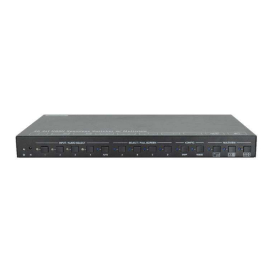
AVG-SCU41-MV
The 4K Multi-view switcher is seamless video scaler
designed to enable a true 4K display. The switcher
features four HDMI inputs and one HDMI output which
allows you to display four video sources on one display.
It also provides a line input, 1 mix input, 1 SPDIF output
and 1 analog output for audio processing.
Control is quick and comprehensive, whether you are
using the front panel, the remote control, RS232
commands, or the fully featured web GUI.
Features
▪ 4 HDMI inputs, 1 HDMI output.
▪ Supports 4K@30Hz 4:4:4, HDCP
2.2.
▪ Seamless switch between 4 input
ports.
▪ Auto Scaler in each source input.
▪ Supports audio embedding and
mixing.
▪ Supports audio de-embedding.
▪ Auto-switching at single window.
▪ Cycles through the windows from A
to D by swap button.
▪ Base on FPGA Technology, layout
and size of the windows can be
customized.
▪ Resizes the windows in 3 different
sizes.
▪ 16 pre-defined layouts for multi-
view.
▪ Multiple control methods, including
an assignable front panel, IR
remote, web GUI and RS232 port.
Advertisement
Table of Contents

Related Manuals for AVGear AVG-SCU41-MV


Summary of Contents for AVGear AVG-SCU41-MV
- Page 1 AVG-SCU41-MV Features ▪ 4 HDMI inputs, 1 HDMI output. ▪ Supports 4K@30Hz 4:4:4, HDCP 2.2. ▪ Seamless switch between 4 input ports. ▪ Auto Scaler in each source input. ▪ Supports audio embedding and mixing. ▪ Supports audio de-embedding. ▪ Auto-switching at single window.
- Page 2 AVG-SCU41-MV PLEASE READ THIS PRODUCT MANUAL CAREFULLY BEFORE USING THIS PRODUCT. This manual is only for operational instruction only, and not to be used for maintenance. The functions described in this version are current as at October 2019. Any changes of functions and operational parameters will be updated in future manual versions.
- Page 3 AVG-SCU41-MV SAFETY OPERATION GUIDE To guarantee the reliable operation of the equipment and safety of the user, please abide by the following procedures in installation, use and maintenance: 1. The system must be earthed properly. Please do not use two blade plugs and ensure the alternating power supply ranges from 100v to 240v and from 50Hz to 60Hz.
-
Page 4: Table Of Contents
AVG-SCU41-MV TABLE OF CONTENTS Introduction ......................1 Production Introduction ..................1.1 Features ......................1.2 What’s in the Box ....................1.3 Panel Description ..................... 2 Front Panel ......................2.1 Rear Panel ......................2.2 System Connection ....................3 Usage Precautions ....................3.1 System Diagram .................... -
Page 5: Introduction
AVG-SCU41-MV 1. Introduction 1.1. Production Introduction The 4K Multi-view switcher is seamless video scaler designed to enable a true 4K display. The switcher features four HDMI inputs and one HDMI output which allows you to display four video sources on one display. It also provides a line input, 1 mix input, 1 SPDIF output and 1 analog output for audio processing. -
Page 6: What's In The Box
AVG-SCU41-MV 1.3. What’s in the Box ▪ 1x AVG-MV41 4k 4x1 Seamless Switcher. ▪ 2x Mounting Ears ▪ 4x Mounting Screws ▪ 4x Plastic Cushions ▪ 1x IR Remote ▪ 2x 3-pin Terminal Block ▪ 1x RS232 Cable (3-pin terminal block to DB9) ▪... -
Page 7: Panel Description
AVG-SCU41-MV 2. Panel Description 2.1. Front Panel ① POWER LED: The LED illuminates green when it is working, and the LED ② IR LED: Built-in IR sensor, receive IR signal sent from IR remote. illuminates red when it is standby. -
Page 8: Rear Panel
AVG-SCU41-MV 2.2. Rear Panel ① HDMI IN: Four type-A female HDMI input ports to connect HDMI source devices. ② LINE IN: 3-pin terminal block to connect audio source device like mobile phone or computer to embed in HDMI audio sources. -
Page 9: System Connection
AVG-SCU41-MV 3. System Connection 3.1. Usage Precautions ▪ Make sure all components and accessories included before installation. ▪ System should be installed in a clean environment with proper temperature and humidity. ▪ All of the power switches, plugs, sockets, and power cords should be insulated and safe. -
Page 10: Front Panel Control
AVG-SCU41-MV 4. Front Panel Control 4.1. Multi-views Selection Factory default is four quarter views, and factory default input and output corresponding relation is input1 -> window A, input2 -> window B, input3 -> window C, input 4-> window D. Press one of the other two multi-view buttons to change layout. -
Page 11: Video Switching Status Inquiry
AVG-SCU41-MV 1) Four input sources priority: HDMI 1 > HDMI 2 > HDMI 3 > HDMI 4. When input source and output window are connected, the corresponding LEDs illuminate blue. 2) Once detecting a new input signal, the switcher will switch to this new signal automatically. -
Page 12: Ir Remote Control
AVG-SCU41-MV Example: In the Full Screen mode RESIZE: Press RESIZE button to readjust the windows size. Please refer the GUI Multi-view Tab on page 12 for more details. Example: In the PIP mode 5. IR Remote Control ① INPUTS: Press 1-4 button to select the input sources. - Page 13 AVG-SCU41-MV Note: There is no long pressing function on this IR remote, and its button functions are the same as the front panel buttons.
-
Page 14: Gui Control
AVG-SCU41-MV 6. GUI Control The switcher can be controlled via TCP/IP. The default IP settings are: IP Address: 192.168.0.178 Subnet Mask: 255.255.255.0 Type 192.168.0.178 in the internet browser, it will enter the below log-in webpage: Username: admin Password: admin Type the user name and password, and then click Login to enter the section for... -
Page 15: Multiview Tab
AVG-SCU41-MV 6.1. Multiview Tab Type the default user name and password, and then click Login to enter the ① Pre-defined Multiview Tab shown as below: ▪ Pre-defined: ✓ Click the corresponding button (Layout1~16) to select video input view and mode. - Page 16 AVG-SCU41-MV ✓ Click Setting button to enter Window Select, and select any one of input sources and corresponding output shown windows. ② User-defined ✓ Click 1, 2, 3, or 4 button to choose User Layout. ✓ Select the corresponding input, set the size and position for each window that you want to display on the layout.
-
Page 17: Audio Tab
AVG-SCU41-MV ✓ Click OK button to exit the current interface and reselect User-defined if the Bandwidth limit exceeded. 6.2. Audio Tab ✓ Click On button to enter Mix mode, Click Off button to exit Mix mode. ✓ Click Unmute or Mute button to control Audio Output. -
Page 18: Resolution Tab
AVG-SCU41-MV 6.3. Resolution Tab ✓ Click any one of built-in resolutions for the selected input source device, click Auto button to show the resolution from third-party display device automatically. ✓ Click Confirm button when the selection is completed. 6.4. RS232 Tab ✓... -
Page 19: Cec Tab
AVG-SCU41-MV ① Source 6.5. CEC Tab ✓ Click Source button to select HDMI input source, and click Function to enter the basic control. ② Display ✓ Click Display buttons to control the third-party display devices. -
Page 20: Edid Tab
AVG-SCU41-MV ③ User-defined ✓ Select corresponding input source devices and display devices to control via CEC commands. ① Upload 6.6. EDID Tab ✓ User-defined EDID can be customized by the below steps: Step 1: Prepare the EDID file (.bin) on the control PC. -
Page 21: Network Tab
AVG-SCU41-MV Step 2: Select the EDID file (.bin) according the tooltip. Step 3: Click Apply to upload the user-defined EDID. ② Setting ✓ Click Setting button to set built-in EDID. ✓ Click HDMI 1-4 button to select input source. ✓ Click any one of built-in EDIDs for the selected input source device. -
Page 22: Tags Tab
AVG-SCU41-MV 6.8. Tags Tab ✓ Modify the input button labels. 6.9. Security Tab ✓ Modify the login password. ✓ Lock or unlock the front panel buttons. -
Page 23: Gui Update
AVG-SCU41-MV 6.10. GUI Update Web-based GUI for the Seamless Switcher supports online update in http://192.168.0.178:100. First, the Switcher is running. Type the username and password (the same as the GUI log-in settings, modified password will be available only after rebooting) to log in the configuration interface. After that, click Administration at the source Tab to get to Upload Program as shown below: Select the desired update file and press Apply, it will start upgrading then. -
Page 24: Rs232 Control
AVG-SCU41-MV 7. RS232 Control Connect the RS232 port to control device (e.g. PC) with RS232 cable. The switcher can be controlled by sending RS232 commands. 7.1. RS232 Control Software Installation: Copy the control software file to the control PC. ⚫... -
Page 25: Rs232 Control Commands
AVG-SCU41-MV Please set the parameters of COM number, bound rate, data bit, stop bit and the parity bit correctly, and then you are able to send command in command sending area. 7.2. RS232 Control Commands Communication protocol: RS232 Communication Protocol... -
Page 26: Signal Switching
AVG-SCU41-MV 7.2.2 Signal Switching Command & Feedback Command Description Example Switch an input AV signal to one or more outputs #SET_AV INPARAM TO OUTPARAM #SET_AV 3 #SET_AV 1 TO A INPARAM = 1 ~ 4 #SET_AV 1 - HDMI 1... -
Page 27: Function Setting
AVG-SCU41-MV Command & Feedback Command Description Example @AUDIO_MUTE 1 Set the audio output source. #SET_AUDIO_SRC PARAM PARAM = 1 ~ 5 1 - HDMI 1 #SET_AUDIO_SRC 1 #SET_AUDIO_SRC 2 - HDMI 2 @AUDIO_SRC 1 3 - HDMI 3 4 - HDMI 4... - Page 28 AVG-SCU41-MV Command & Feedback Command Function Example #SET_OUTPUT_RES PARAM PARAM = 1 ~ 8 1 - 1024x768 60 HZ 2 - 1280x720 60 HZ 3 - 1360x768 60 HZ 4 - 1600x1200 60 Hz 5 - 1920x1080 60 HZ 6 - 1920x1200 60 HZ...
- Page 29 AVG-SCU41-MV Command & Feedback Command Function Example 2 - HDMI 2 3 - HDMI 3 4 - HDMI 4 #UPLOAD_USER_EDID @USER_EDID READY #UPLOAD_USER_E Upload the user defined EDID PLEASE SEND EDID DATA IN 10S Lock/unlock the keypad #SET_KEYPAD_LOCK #SET_KEYPAD_LOC PARAM...
- Page 30 AVG-SCU41-MV Command & Feedback Command Function Example 20 - USER CONFIG 4 #GET_MV_MODE #GET_MV_MODE Get multiview mode @MV_MODE 1 #GET_STATUS #GET_STATUS Get the system status … … #SET_SWAP_SRC @SWAP_SRC @VIDEO #SET_SWAP_SRC Swap input source OUT A B C D IN 1 2 3 4...
-
Page 31: Cec Commands
AVG-SCU41-MV Command & Feedback Command Function Example #SET_AUTO_POWER PARAM PARAM = 0 ~ 1 0 - DISABLED 1 - ENABLED #GET_AUTO_POWE Get the auto power function #GET_AUTO_POWER state @AUTO_POWER 1 Set the DISPLAY OFF message loop counter #SET_OFF_CNT 1 #SET_OFF_CNT... - Page 32 AVG-SCU41-MV Command & Command Function Feedback Example PARAM = 1 ~ 4 1 - HDMI 1 2 - HDMI 2 3 - HDMI 3 4 - HDMI 4 Send CEC LEFT command to source #SET_SRC_LEFT PARAM PARAM = 1 ~ 4...
- Page 33 AVG-SCU41-MV Command & Command Function Feedback Example 2 - HDMI 2 3 - HDMI 3 4 - HDMI 4 Send CEC OFF command to source #SET_SRC_OFF PARAM #SET_SRC_OFF 1 #SET_SRC_OFF PARAM = 1 ~ 4 @SRC_OFF 1 1 - HDMI 1...
- Page 34 AVG-SCU41-MV Command & Command Function Feedback Example 3 - HDMI 3 4 - HDMI 4 Send CEC NEXT command to source #SET_SRC_NEXT PARAM #SET_SRC_NEXT 1 #SET_SRC_NEXT PARAM = 1 ~ 4 @SRC_NEXT 1 1 - HDMI 1 2 - HDMI 2...
-
Page 35: Special Commands
AVG-SCU41-MV 7.2.6 Special Commands Note: The below commands don’t need ending mark. Command & Command Description Feedback Example Send the command "XXXX" to the 3th device while the system enter power on mode. #SET_ON_05:123456 #SET_ON_(PARAM):XXX 1234567 PARAM = 01~07 (When the power is... - Page 36 AVG-SCU41-MV Command & Command Description Feedback Example while the system enter ABCDEFG power off or standby mode. (When the power is #SET_OF_(PARAM):XXXX connected successfully, the serial PARAM = 01~07 port directly sends: 01 - 115200 ABCDEFG) 02 - 57600 03 - 38400...
-
Page 37: Firmware Upgrade
AVG-SCU41-MV 8. Firmware Upgrade 1) Prepare the latest upgrade file (.bin) and rename it as “FW_MV bin” on PC. 2) Power off the switcher and connect the FIRMWARE port of switcher to the PC with Type-A USB cable. 3) Power on the switcher and then the PC will automatically detect a U-disk named of “BOOTDISK”. -
Page 38: Specification
AVG-SCU41-MV 10. Specification Video Video Input (4) HDMI IN (1~4) Video Input Connector (4) Type-A female HDMI HDMI Input Resolution Up to 4K@30Hz 4:4:4 Video Output (1) HDMI Video Output Connector (1) Type-A female HDMI HDMI Output Resolution Up to 4K@30Hz RGB HDMI Standard HDMI 1.4b... - Page 39 AVG-SCU41-MV < 0.05 dB, 1 kHz sine at 0 dBFS level (or max level L-R Level Deviation before clipping) 1k ohm and higher (supports 10x paralleled 10k ohm Output Load Capability loads) Noise -80dB Control Control port (1)RS232, (1)TCP/IP Control Connector (1) 3-pin terminal connector, (1) RJ45.
-
Page 40: Troubleshooting & Maintenance
AVG-SCU41-MV 11. Troubleshooting & Maintenance Problems Potential Causes Solutions Bad quality of the connecting Try another high-quality Output image with white cable cable. noise. Make sure the Fail or loose connection connection is good. Check with oscilloscope No signal at the input / output or multimeter if there is end.
Need help?
Do you have a question about the AVG-SCU41-MV and is the answer not in the manual?
Questions and answers