
Related Manuals for GIGAIPC QBiX-PPC Series


Summary of Contents for GIGAIPC QBiX-PPC Series
-
Page 1: Industrial Panel Pc System
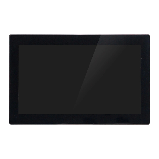
QBiX-PPC-156A8145T-A1 (PS-8145A-SI) 15.6” Industrial Panel PC System Quick Start Guide www.gigaipc.com... -
Page 2: Copyright Notice
While reasonable efforts have been made in the preparation of this document to assure its accuracy, GIGAIPC assumes no liabilities resulting from errors or omissions in this document, or from the use of the information contained herein. -
Page 3: Acknowledgement
Core, Atom are trademarks of Intel Corporation • • ITE is a trademark of Integrated Technology Express, Inc. IBM, PC/AT, PS/2, and VGA are trademarks of International Business • Machines Corporation. All other product names or trademarks are properties of their respective owners. www.gigaipc.com... -
Page 4: Packing List
Before setting up your product, please make sure the following items have been shipped: Item Quantity System kit Terminal Blocks Male Plug Thermal pad for Memory (25ST3-200086-T5R) USB 2.0 Female cable If any of these items are missing or damaged, please contact your distributor or sales representative immediately. www.gigaipc.com... -
Page 5: About This Document
(if any), its specifications, dimensions, jumper/ connector settings/definitions, and driver installation instructions (if any), to facilitate users in setting up their product. Users may refer to the GIGAIPC.com for the latest version of this document. www.gigaipc.com... -
Page 6: Safety Precautions
Make sure the device is installed near a power outlet and is easily accessible. 10. Keep this device away from humidity. 11. Place the device on a solid surface during installation to prevent falls 12. Do not cover the openings on the device to ensure optimal heat dissipation. www.gigaipc.com... - Page 7 18. D O N O T L E AV E T H I S D E V I C E I N A N U N C O N T R O L L E D ENVIRONMENT WITH TEMPERATURES BEYOND THE DEVICE’S PERMITTED STORAGE TEMPERATURES (SEE CHAPTER 1) TO PREVENT DAMAGE. www.gigaipc.com...
-
Page 8: Fcc Statement
Skilled person have to pay special attention or take special protection. Only authorized by well trained professional person can access the restrict access location. (2) External metal parts are hot!! Before touching it, special attention or protection is necessary www.gigaipc.com... -
Page 9: Table Of Contents
(Wireless Module inclusion may vary based on local distribution) ..............22 C) Mini PCIe Card Installation: How to safely install the Mini PCIe Card ............. 23 D) M.2 SSD Installation: How to safely install the M.2 2280 SSD ..............24 E) 2.5” HDD/SSD installation ......... 25 www.gigaipc.com... - Page 10 3.2.13 BKL_CN (Backlight Control connector) ......46 3.2.14 SYS_PANEL (Front panel header) ........47 3.2.15 LVDS (LVDS connector) ..........48 3.2.16 LSW (LVDS resolution jumper) ........49 3.2.17 BATTERY (Battery cable connector) ......50 3.2.18 LPC_CN (LPC Connector) ..........51 www.gigaipc.com...
- Page 11 IT8786 Super I/O Configuration ........70 4.3.5 Hardware Monitor ............71 4.3.6 S5 RTC Wake Settings ........... 72 4.3.7 CSM Configuration ............73 4.3.8 NVMe Configuration ............74 4.3.9 Offboard SATA Controller Configuration ...... 75 4.3.10 Digital IO Port Configuration ........76 www.gigaipc.com...
- Page 12 Chipset ................77 Security ................. 78 Boot ................81 Save & Exit ..............82 www.gigaipc.com...
-
Page 13: Chapter 1 - Product Specifications
Chapter 1 Chapter 1 - Product Specifications www.gigaipc.com... - Page 14 252.6 180.5 www.gigaipc.com...
-
Page 15: Specifications
4 x USB 3.2 Gen 2x1 1 x GPIO (8 bits) 1 x COM Port (RS-232/422/485 & RI/5V/12V) 1 x COM Port (RS-232/422/485) 2 x HDMI 1 x 3-pin Terminal block 1 x Power button with LED 2 x External Antenna Holes (Optional) www.gigaipc.com... - Page 16 Carton size: 490 x 336 x 175 (mm) Packing Capacity: 1pc Packaging Including: Content Thermal Pad for Memory x 1 (P/N: 25ST3-200086-T5R) Terminal Blocks Male Plug x 1 USB 2.0 Female cable x 1 Order System: 6BPS8145AMR-SI (Box packing) Information www.gigaipc.com...
-
Page 17: Chapter 2 - Qbix-Ppc-156A8145T-A1
Chapter 2 Chapter 2 – QBiX-PPC-156A8145T-A1 Industrial Panel PC System Kit www.gigaipc.com... -
Page 18: Dimension
Dimension 252.6 180.5 www.gigaipc.com... -
Page 19: Getting Familiar With Your Unit
[Right Side] 1 x COM Port (COM2, RS-232/422/485) 1 x GPIO (8 bits) 2 x RJ45 LAN Ports 4 x USB 3.2 Gen 2x1 1 x 3-pin Terminal Block 2 x HDMI 1 x COM Port (COM1, RS-232/422/485 & RI/5V/12V) www.gigaipc.com... - Page 20 [Bottom PCB Side] Information Information 1 x Mini PCIe slot (PCIe x1 + 2 x DDR4 SO-DIMM sockets USB2.0) with SIM Slot 1 x M.2 slot (Support NGFF-2230) D 1 x M.2 slot (Support NGFF-2280) support 2.5’’ Hard drive/SSD www.gigaipc.com...
-
Page 21: A) Memory Installation: Ddr4 So-Dimm
A) Memory Installation: DDR4 SO-DIMM Remove 4 screws and disassemble the heat-plate. SO-DIMM SO-DIMM www.gigaipc.com... -
Page 22: B) Wireless Module: How To Safely Install The Module (Wireless Module Inclusion May Vary Based On Local Distribution)
Carefully insert the wireless module into the M.2 slot plate, and then remove the screw from the screw hole. (Location : MSO2) SO-DIMM 青山依舊在,幾度夕陽紅。慣看秋月春風。一 壺濁酒喜相逢,浪花淘盡英雄。是非成敗轉頭 Lock the screw in the middle. Install the antenna on the left side of the connection wireless module down. www.gigaipc.com... -
Page 23: C) Mini Pcie Card Installation: How To Safely Install The Mini Pcie Card
Lock the screw in the middle. Carefully insert the wireless module into the M.2 slot heat-plate. hole (Location : MSO1) 鎖入固定於無線模組中央頂端的螺 小心地將無線模組安裝於M.2插槽中。 絲。 Secure the Mini PCIe Card with screw. Carefully insert the Mini PCIe Card into the slot. www.gigaipc.com... -
Page 24: D) M.2 Ssd Installation: How To Safely Install The
D) M.2 SSD Installation: How to safely install the M.2 2280 SSD Remove the screw from the screw hole (Loca�on : Remove 4 screws and disassemble the heat-plate. MSO3) Carefully insert the M.2 SSD into the slot, and secure with screw. www.gigaipc.com... -
Page 25: E) 2.5" Hdd/Ssd Installation
E) 2.5” HDD/SSD installation Install 2nd 2.5” HDD with 4 screws. Install 1st 2.5” HDD with 4 screws. Torsion : 1.0~1.5 kgf-cm Torsion : 1.0~1.5 kgf-cm www.gigaipc.com... -
Page 26: Antenna Installation (Antenna Inclusion May Vary Based On Local Distribution)
Antenna Installation (Antenna inclusion may vary based on local distribution) www.gigaipc.com... -
Page 27: Cable Pin-Define
RS-485 DB9 Pin RS-232 Full Duplex Half Duplex TXD- TXD+ RXD+ – RXD- – – – – – – – – – 2. DBP DIO (25CR5-150606-S9R) DBP DIO Pin Pin Name GPIO-output_1 GPIO-input_1 GPIO-output_2 GPIO-input_2 GPIO-output_3 GPIO-input_3 GPIO-output_4 GPIO-input_4 www.gigaipc.com... -
Page 28: Support
Support ● For a list of tested memory, M.2, 2.5’’ SSD, wireless adapters and OS supported, go to: http://www.gigaipc.com ● To download the latest drivers and BIOS updates, go to: http://www. gigaipc.com ● For product support, go to: http://www.gigaipc.com www.gigaipc.com... -
Page 29: Safety And Regulatory Information
At the end of its serviceable life, this product should not be treated as household or general waste. It should be handed over to the applicable collection point for the recycling of electrical and electronic equipment, or returned to the supplier for disposal. www.gigaipc.com... -
Page 30: Chapter 3 - Hardware Information
Chapter 3 Chapter 3 – Hardware Information www.gigaipc.com GIGAIPC reserves the right to modify or revise the content at anytime without prior notice. -
Page 31: Jumpers And Connectors
Jumpers and Connectors www.gigaipc.com GIGAIPC reserves the right to modify or revise the content at anytime without prior notice. - Page 32 Front panel header 15 LVDS LVDS connector 16 LSW LVDS resolution jumper 17 BATTERY Battery cable connector 18 LPC_CN LPC Connector SODIMM1 DDR4 SO-DIMM Slot SODIMM2 www.gigaipc.com GIGAIPC reserves the right to modify or revise the content at anytime without prior notice.
- Page 33 USB 3.2 Gen 2x1 Connector x 4 RUSB31_2 25 HDMI21 HDMI connector 26 LAN1, LAN2 LAN connector Serial Port connector 27 COM1 (RS-232/422/485 & RI/5V/12V) www.gigaipc.com GIGAIPC reserves the right to modify or revise the content at anytime without prior notice.
-
Page 34: Cpu Fan (Cpu Fan Connector)
3.2.1 CPU FAN (CPU FAN connector) Pin 1 CPU FAN connector Connector PN Vendor 85205-0470N ACES A1250WV-S-04PC JOINT-TECH Pin No. Definition Detect Speed Control www.gigaipc.com GIGAIPC reserves the right to modify or revise the content at anytime without prior notice. -
Page 35: System Fan (System Fan Connector)
3.2.2 System FAN (System FAN connector) Pin 1 System FAN connector Connector PN Vendor 85205-0470N ACES A1250WV-S-04PC JOINT-TECH Pin No. Definition Detect Speed Control www.gigaipc.com GIGAIPC reserves the right to modify or revise the content at anytime without prior notice. -
Page 36: Jcom1 (Com1 Ri# Pin Ri#/5V/12V Select)
JCOM11 Jumper Select Connector PN Vendor 220-97-03GB01 PINREX 1-2 Close: 5V (Power COM) PH06N53BAZ000 HORNGTONG 3-4 Close: RI (Stand COM) (Default-Setting) 5-6 Close: 12V (Power COM) www.gigaipc.com GIGAIPC reserves the right to modify or revise the content at anytime without prior notice. -
Page 37: Com2, Com3, Com4 (Serial Port Header, Rs-232)
COM2, COM3, COM4 (Serial port header, RS-232) Pin 1 Serial Port Cable Connector Connector PN Vendor 725-81-10TW00 PINREX A2004WV-2X05P46 JOINT-TECH Pin No. Definition No Connect www.gigaipc.com GIGAIPC reserves the right to modify or revise the content at anytime without prior notice. -
Page 38: Fusb (Usb 2.0 Header)
3.2.5 FUSB (USB 2.0 header) Pin 1 USB 2.0 Header Connector PN Vendor 210-92-05GB04 PINREX PH10R53BAZ009 HORNGTONG Pin No. Definition No Pin No Connect www.gigaipc.com GIGAIPC reserves the right to modify or revise the content at anytime without prior notice. -
Page 39: Sataiii_0, Sataiii_1 (Sata 6Gb/S Connector)
3.2.6 SATAIII_0, SATAIII_1 (SATA 6Gb/s Connector) SATA Connector SATAIII_1,SATAIII_0 Connector PN Vendor WATM-07ABNB2BAUW3 WINWIN 770-83-07SW19 PINREX Pin No. Definition www.gigaipc.com GIGAIPC reserves the right to modify or revise the content at anytime without prior notice. -
Page 40: Gpio_Cnt (General Purpose Input/Output Header)
GPIO Connector Connector PN Vendor 725-81-12TW00 PINREX A2004WV-2X06P46 JOINT-TECH Pin No. Definition GPIO-output_1 GPIO-input_1 GPIO-output_2 GPIO-input_2 GPIO-output_3 GPIO-input_3 GPIO-output_4 GPIO-input_4 SMBus Clock SMBus DATA www.gigaipc.com GIGAIPC reserves the right to modify or revise the content at anytime without prior notice. -
Page 41: Satapw1, Satapw2 (Sata Power Connector)
3.2.8 SATAPW1, SATAPW2 (SATA power connector) Pin 1 Hard Disk Power Connector Connector PN Vendor 743-81-04TW00 PINREX WF04Q2-3BJQ000 HORNGTONG Pin No. Definition www.gigaipc.com GIGAIPC reserves the right to modify or revise the content at anytime without prior notice. -
Page 42: At_Cn (At/Atx Mode Select Jumper)
PINREX PH03N2-7BAN000 HORNGTONG Pin No. Definition AT MODE TXD5 ATX MODE Jumper setting 1-2 Close : AT mode. 2-3 Close : ATX mode.(Default setting) www.gigaipc.com GIGAIPC reserves the right to modify or revise the content at anytime without prior notice. -
Page 43: Dc_In (Dc In 1X4-Pin Power Connector )
3.2.10 DC_IN (DC IN 1x4-pin power connector ) Pin 1 DC in connector Connector PN Vendor 753-81-04TW00 PINREX Pin No. Definition Power Power www.gigaipc.com GIGAIPC reserves the right to modify or revise the content at anytime without prior notice. -
Page 44: Spk_Out (Speaker Out Connector)
Audio Amplifie Connector Connector PN Vendor 721-81-045W00 PINREX A2001WV-04P146 JOINT-TECH Pin No. Definition Speaker Out L+ Speaker Out L- Speaker Out R- Speaker Out R+ www.gigaipc.com GIGAIPC reserves the right to modify or revise the content at anytime without prior notice. -
Page 45: Fp_Audio (Front Audio Connector)
Pin 1 Front Audio Connector Connector PN Vendor 725-81-10TW00 PINREX A2004WV-2X05P46 JOINT-TECH Pin No. Definition MIC_L MIC_R Detect HPOUT_R MIC_JD FAUDIO_JD No Connect HPOUT_L www.gigaipc.com GIGAIPC reserves the right to modify or revise the content at anytime without prior notice. -
Page 46: Bkl_Cn (Backlight Control Connector)
3.2.13 BKL_CN (Backlight Control connector) Pin 1 Backlight Control connector Connector PN Vendor 721-81-05TW00 PINREX A2001WV-05P146 JOINT-TECH Pin No. Definition Backlight Enable www.gigaipc.com GIGAIPC reserves the right to modify or revise the content at anytime without prior notice. -
Page 47: Sys_Panel (Front Panel Header)
Vendor 210-92-05G111 PINREX Pin No. Definition HDD LED+ Power LED+ HDD LED- Power LED- Power Button+ Reset Button Power Button- No Connect No Pin www.gigaipc.com GIGAIPC reserves the right to modify or revise the content at anytime without prior notice. -
Page 48: Lvds (Lvds Connector)
Note: *The LVDS output connector of the unit is only intended to be connected to an UL/IEC/EN approval equipment with fire enclosure. CLK2+ CLK1+ CLK2- CLK1- www.gigaipc.com GIGAIPC reserves the right to modify or revise the content at anytime without prior notice. -
Page 49: Lsw (Lvds Resolution Jumper)
1280 x 960 1600 x 1200 18bit 24bit 1280 x 1024 1920 x 1080 24bit 24bit 1366 x 768 1920 x 1200 18bit 24bit www.gigaipc.com GIGAIPC reserves the right to modify or revise the content at anytime without prior notice. -
Page 50: Battery (Battery Cable Connector)
3.2.17 BATTERY (Battery cable connector) Pin 1 Battery Cable Connector Connector PN Vendor 85205-0270L ACES A1250WV-S-02PC JOINT-TECH Pin No. Definition 3.3V www.gigaipc.com GIGAIPC reserves the right to modify or revise the content at anytime without prior notice. -
Page 51: Lpc_Cn (Lpc Connector)
3.2.18 LPC_CN (LPC Connector) Pin 1 LPC_CN Connector Pin No. Definition CK_LPC1 LFRAME# LAD0 PLT_RST_80H LAD1 LAD3 LAD2 3.3V SERIRQ www.gigaipc.com GIGAIPC reserves the right to modify or revise the content at anytime without prior notice. -
Page 52: Sodimm1, Sodimm2 (Ddr4 So-Dimm Slot)
3.2.19 SODIMM1, SODIMM2 (DDR4 SO-DIMM Slot) www.gigaipc.com GIGAIPC reserves the right to modify or revise the content at anytime without prior notice. -
Page 53: M2E (M.2 Slot, E-Key, Ngff2230, Wifi & Bluetooth Module)
Pin No. Definition PCIE_WAKE BT_Disable# WIFI_Disable# USB_D+ USB_D- BT_WAKE Connector PN Vendor APCI0095-P002A LOTES Pin No. Definition Pin No. Definition 80152-8521 BELLWETHER WLAN_TXp WLAN_TXn CL_RST# www.gigaipc.com GIGAIPC reserves the right to modify or revise the content at anytime without prior notice. -
Page 54: Mpcie (Mini Pcie Full Size, Support 3G/4G Module)
Connector PN Vendor PCIE_ SIM_PWR AS0B221-S99Q-7H FOXCONN CLKREQ# SIM_DATA PCIE_CLK# SIM_CLK PCIE_CLK SIM_RST SIM_VPP PCIE_DISABLE PCIRST# PCIE_RXn 3.3V PCIE_RXp 1.5V SMBCLK PCIE_TXn SMBDATA PCIE_TXp www.gigaipc.com GIGAIPC reserves the right to modify or revise the content at anytime without prior notice. -
Page 55: M2M (M.2 Slot, Sata/Pcie X4, Ngff2280)
3.3V Pin No. Definition Pin No. Definition 3.3V SUSCLK 3.3V 3.3V M2_SSD_ 3.3V Detect 3.3V 3.3V Connector PN Vendor PCIE_RXn 80159-8521 BELLWETHER PCIE_RXp PCIE_TXn www.gigaipc.com GIGAIPC reserves the right to modify or revise the content at anytime without prior notice. -
Page 56: Sim_Card (Sim Card Slot)
3.2.23 SIM_CARD (SIM Card slot) www.gigaipc.com GIGAIPC reserves the right to modify or revise the content at anytime without prior notice. -
Page 57: Rusb31_1, Rusb31_2 (Usb 3.2 Gen 2X1 Connector)
3.2.24 RUSB31_1, RUSB31_2 (USB 3.2 Gen 2x1 connector) USB Connector Connector PN Vendor UAA111C-841R1-4H FOXCONN Definition Definition USB_D- USB_D- USB_D+ USB_D+ USB3_RX- USB3_RX- USB3_RX+ USB3_RX+ USB3_TX- USB3_TX- USB3_TX+ USB3_TX+ www.gigaipc.com GIGAIPC reserves the right to modify or revise the content at anytime without prior notice. -
Page 58: Hdmi21 (Hdmi Connector)
HDMI Connector Connector PN Vendor QJ11191-DFB1-4F FOXCONN Pin No. Definition Pin No. Definition HDMI_D2+ HDMI_D2- HDMI_SCL HDMI_D1+ HDMI_SDA HDMI_D1- HDMI_D0+ HDMI_HPD HDMI_D0- HDMI_CLK+ HDMI_CLK- www.gigaipc.com GIGAIPC reserves the right to modify or revise the content at anytime without prior notice. -
Page 59: Lan1, Lan2 (Lan Connector)
10Mbps data rate Link / Connection/ Activity LED Speed LED Pin No. Definition Connector PN Vendor TX1+ RB1-13NB5N5A TX1- TX2+ TX2- TX3+ TX3- TX4+ TX4- www.gigaipc.com GIGAIPC reserves the right to modify or revise the content at anytime without prior notice. -
Page 60: Com1 (Serial Port Connector, Rs-232/422/485 & Ri/5V/12V)
FENYING Pin No. RS-232 RS-422 RS-485 Full Duplex Half Duplex TXD- TXD+ RXD+ – RXD- – – – – – – – – – www.gigaipc.com GIGAIPC reserves the right to modify or revise the content at anytime without prior notice. - Page 61 GIGAIPC reserves the right to modify or revise the content at anytime without prior notice.
-
Page 62: Chapter 4 - Bios
Chapter 4 Chapter 4 – BIOS www.gigaipc.com... -
Page 63: Introduction
Execute command or enter the submenu Increase the numeric value or make + changes Decrease the numeric value or make – changes General Help Previous Values Load Optimized Defaults Settings Save changes & Exit the BIOS Setup program Exit the BIOS Setup program www.gigaipc.com... -
Page 64: The Main Menu
ME FW version Shows ME firmware version Set the Date for the system System Date (Format : Weekday - Month - Day - Year) Set the time for the system System Time (Format : Hour - Minute - Second) www.gigaipc.com... -
Page 65: Advanced
Advanced The Advanced menu is to configure the functions of hardware settings through submenu. Use arrow keys to move among the items, and press <Enter> to access into the related submenu. www.gigaipc.com... -
Page 66: Tpm Configuration
4.3.1 TPM Configuration Use TPM Configuration submenu to choose TPM interface. Item Description PTT : Internal TPM (Default setting) TPM Device dTPM : External TPM (When using External TPM module or Selection having TPM chip on MB) www.gigaipc.com... - Page 67 Item Description Security Device Enabled : Enables TPM feature (Default setting) support Disabled : Disables TPM feature Item Description None : No execution will be conducted (Default setting) Pending operation TPM clear : Set to clear data on TPM www.gigaipc.com...
-
Page 68: Sata And Rst Configuration
Intel RST Premium With Intel Optane System Acceleration : Enables RAID Selection mode for the SATA controller Serial ATA Port 0 shows 2.5" SATA HDD/SSD information Serial ATA Port 1 shows 2.5" SATA HDD/SSD information shows M.2 SATA interface SSD information www.gigaipc.com... -
Page 69: Cpu Configuration
CPU voltage and core frequency to decrease heat and power Intel(R) consumption for power saving. SpeedStep(tm) Enabled : Enables Intel SpeedStep Technology (Default setting) Disabled : Disables Intel SpeedStep Technology Enabled : Configure MSR 0xE2[15] , CFG Lock bit (Default setting) CFG Lock Disabled : Disables CFG Lock www.gigaipc.com... -
Page 70: It8786 Super I/O Configuration
Serial Port 2 Enabled : Enables allows you to configure the serial port settings Configuration Disabled : if Disabled, displays no configuration for the serial port Device settings : Display the specified Serial Port base I/O address and IRQ www.gigaipc.com... -
Page 71: Hardware Monitor
4.3.5 Hardware Monitor Item Description CPU temperature Shows current CPU temperature System temperature Shows current system temperature www.gigaipc.com... -
Page 72: S5 Rtc Wake Settings
Enable or Disable System to wake on a specific time. Wake system Disabled : Disables system to wake on a specific time (Default setting) from S5 Fixed Time : Enables system to wake on a specific time (Format : hr : min : sec) www.gigaipc.com... -
Page 73: Csm Configuration
Disabled : UEFI Mode only (Default setting) Enabled : Enables Legacy Mode feature When system is power on, install LAN driver under UEFI mode Network Stack Disabled : Disables UEFI Network Stack (Default setting) Enabled : Enables UEFI Network Stack www.gigaipc.com... -
Page 74: Nvme Configuration
4.3.8 NVMe Configuration NVMe Configuration shows information when your M.2 NVMe PCIe SSD is installed. www.gigaipc.com... -
Page 75: Offboard Sata Controller Configuration
4.3.9 Offboard SATA Controller Configuration www.gigaipc.com... -
Page 76: Digital Io Port Configuration
Enabled : If Digital IO Output value/level is modified in OS, they will be memorized and kept. SOGPO_1 (Pin 1) SOGPI_1 (Pin 2) SOGPO_2 (Pin 3) SOGPI_2 (Pin 4) Configure Digital IO Input or Output values for each pin. SOGPO_3 (Pin 5) SOGPI_3 (Pin 6) SOGPO_4 (Pin 7) SOGPI_4 (Pin 8) www.gigaipc.com... - Page 77 Enable/Disable Watchdog Timer function Watchdog Timer Enabled : Enables Watchdog Timer function Disabled : Disabled Watchdog Timer function (Default setting) Enable/Disable BIOS Lock function BIOS Lock Enabled : Enables BIOS Lock function (Default setting) Disabled : Disabled BIOS Lock funtion www.gigaipc.com...
- Page 78 To set up Administrator's password Administrator Minimum length : 3 Password Maximum length : 20 To set up User's password User Password Minimum length : 3 Maximum length : 20 Secure Boot Press <Enter> to configure the advanced items www.gigaipc.com...
- Page 79 No : Cancel to restore factory settings Reset To Setup Yes : Agree to setup mode Mode No : Cancel to setup mode Enables expert users to modify Secure boot policy variables without full Key Management authentication Press <Enter> to configure the advanced items www.gigaipc.com...
- Page 80 'UEFI CA' from database from DB No : Cancel to remove 'UEFI CA' from database Restore DB variables to fac tor y Restore DB defaults defaults Yes : Agree to restore DB defaults No : Cancel to restore DB defaults www.gigaipc.com...
- Page 81 Enabled : Enables Full screen LOGO Show on POST screen LOGO Show Disabled : Disables Full screen LOGO Show on POST screen (Default setting) Boot Option #1 Shows the information of the storage that be installed in the system Boot Option #2 Choose/set the boot priority www.gigaipc.com...
- Page 82 Yes : Agree to load optimized defaults No : Cancel to load optimized defaults Enable/Disable Me FW image re-flash function Me FW Image Enabled : Enables Me FW image re-flash function Re-Flash Disabled : Disables Me FW image re-flash function (Default setting) www.gigaipc.com...
Need help?
Do you have a question about the QBiX-PPC Series and is the answer not in the manual?
Questions and answers