
Related Manuals for Unverferth BRENT 578


Summary of Contents for Unverferth BRENT 578
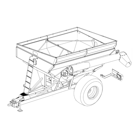
- Page 1 Grain Handling GRAIN CART MODEL 578 Serial Number D67710100 & Higher Part No. 2010887...
- Page 2 The information, specifications, and illustrations in the manual are based on information available at the time it was written. Due to continuing improvements in the design and manufacture of Unverferth products, all specifications and information contained herein are subject to change without notice.
- Page 3 Please fill out and retain this portion for your records. All products manufactured by Unverferth Mfg. Co., Inc. are warranted to be free from material and workmanship defects for one full year from time of consumer delivery. Your local dealer will gladly assist you with any warranty questions.
-
Page 4: Table Of Contents
Brent 578 — Introduction Table of Contents SECTION I Safety General Hazard Information ....................... 1-2 Safety Decals ..........................1-3 Following Safety Instructions ..................... 1-4 Before Servicing ......................... 1-4 Before Operating ........................1-4 During Operation ........................1-5 Before Transporting ........................1-5 During Transport ......................... - Page 5 Brent 578 — Introduction Table of Contents SECTION II Set Up Set Up Checklist ........................2-2 Basic Cart Set Up Folding Side Extension Set Up ................... 2-2 Ladder ..........................2-3 Jack ............................. 2-3 Standard Chute Installation ....................2-4 Optional Extension Chute ....................2-4 Optional Hydraulic Adjustable Spout ...................
- Page 6 Brent 578 — Introduction Table of Contents SECTION III Operation General Operation Information ....................3-2 Preparing Tractor ........................3-2 Preparing Cart Inspection ..........................3-3 Lubrication ........................... 3-3 Hitching To Tractor Drawbar Connection ......................3-4 Jack ............................. 3-4 Transport Chain Connection ....................3-5 Hydraulic Connections ......................
- Page 7 Brent 578 — Introduction Table of Contents SECTION IV Maintenance Lubrication ..........................4-2 Gearbox Lubrication ........................4-3 Seasonal Storage ........................4-3 Hydraulic System ........................4-4 Verify Telescoping PTO Shaft Length ..................4-6 Auger Driveline ........................... 4-8 PTO Shaft & Clutch ......................... 4-11 PTO Quick Disconnect ......................
- Page 8 Brent 578 — Introduction Table of Contents SECTION V Parts Final Assembly ........................... 5-2 Hitch ............................5-4 Axle ............................5-5 Hub ............................. 5-6 Wheels & Tires .......................... 5-7 Decals ............................5-8 Sideboards ..........................5-10 Electrical ........................... 5-12 Auger & Hydraulics ........................5-14 Upper Auger ..........................
- Page 9 — Safety Brent 578 SECTION I Safety General Hazard Information ....................... 1-2 Safety Decals ..........................1-3 Following Safety Instructions ..................... 1-4 Before Servicing ......................... 1-4 Before Operating ........................1-4 During Operation ........................1-5 Before Transporting ........................1-5 During Transport ......................... 1-5 Driveline Safety ..........................
-
Page 10: Safety
It is said that, “the best kind of a safety device is a careful operator.” We, at Unverferth Mfg. Co., Inc. ask that you be that kind of operator. -
Page 11: Safety Decals
— Safety Brent 578 Safety Decals • REPLACE LOST, DAMAGED, PAINTED, OR UNREADABLE DECALS IMMEDIATELY. PARTS THAT HAVE DECALS ARE REPLACED, ALSO MAKE SURE TO INSTALL NEW DECALS. THESE DECALS INFORM AND REMIND THE OPERATOR WITH OPERATIONAL INFORMATION AND SAFETY MESSAGES. -
Page 12: Following Safety Instructions
— Safety Brent 578 Follow Safety Instructions • Read and understand this operator’s manual before operating. • All machinery should be operated only by trained and authorized personnel. • To prevent machine damage, use only attachments approved by the manufacturer. -
Page 13: During Operation
— Safety Brent 578 During Operation • Regulate speed to field conditions. Maintain complete control at all times. • Never service or lubricate cart when in operation. • Keep away from overhead power lines. Electrical shock can cause serious injury or death. -
Page 14: Driveline Safety
— Safety Brent 578 Driveline Safety • Do not allow children near equipment that is running or engaged. • Do not exceed 1000 RPM PTO speed. • Disengage the PTO, stop the tractor engine, and remove the key from the ignition before making inspections, or performing maintenance and repairs. -
Page 15: Pressurized Oil
— Safety Brent 578 Pressurized Oil • Relieve the hydraulic system of all pressure before adjusting or servicing. See hydraulic power unit manual for procedure to relieve pressure. • High-pressure fluids can penetrate the skin and cause serious injury or death. Use cardboard or wood to detect leaks in the hydraulic system. -
Page 16: Preparing For Emergencies
— Safety Brent 578 Preparing for Emergencies • Keep a first aid kit and properly rated fire extinguisher nearby. • Keep emergency numbers for fire, rescue, and poison control personnel near the phone. Wearing Protective Equipment • Wear clothing and personal protective equipment appropriate for the job. - Page 17 — Set Up Brent 578 SECTION II Set Up Set Up Checklist ........................2-2 Basic Cart Set Up Folding Side Extension Set Up ................... 2-2 Ladder ..........................2-3 Jack ............................. 2-3 Standard Chute Installation ....................2-4 Optional Extension Chute ....................2-4 Optional Hydraulic Adjustable Spout ...................
-
Page 18: Basic Cart Set Up
— Set Up Brent 578 Pre-Delivery Checklist After the cart has been completely assembled, use the following checklist and inspect the cart. Check off each item as it is found satisfactory or after proper adjustment is made. Torque wheel nuts and check tire pressure as specified in MAINTENANCE section page 4-19. -
Page 19: Folding Side Extension Set Up
— Set Up Brent 578 Basic Cart Set Up (Continued) Folding Side Extension Set Up Hardware is stored behind right axle standard Hinge of grain cart. Support 1. Rotate extensions up into position and secure at corner holes. 2. Attach center support hardware. -
Page 20: Standard Chute Installation
— Set Up Brent 578 Basic Cart Set Up (Continued) Standard Chute Installation 1. Position chute assembly over the upper auger tube outlet shroud with overlap towards hitch. 2. Hold with capscrew in top hole and secure with eight capscrews, flat washers and locknuts. -
Page 21: Driveline Storage
— Set Up Brent 578 Basic Cart Set Up (Continued) Driveline Storage Storage brackets are located on the inside right frame rail. Secure the PTO shaft to these brackets for extended transporting or seasonal storage. • Remove and store the complete PTO before towing grain cart behind a delivery truck. - Page 22 — Set Up Brent 578 Notes...
- Page 23 — Operation Brent 578 SECTION III Operation General Operation Information ....................3-2 Preparing Tractor ........................3-2 Preparing Cart Inspection ..........................3-3 Lubrication ........................... 3-3 Hitching To Tractor Drawbar Connection ......................3-4 Jack ............................. 3-4 Transport Chain Connection ....................3-5 Hydraulic Connections ......................3-5 Electrical Connections ......................
-
Page 24: Preparing Tractor
— Operation Brent 578 Operating Checklist o Read and understand all safety precautions before operating cart. Check axle spacing to be sure axle is adjusted from shipping position to desired operating width. (If Applicable) Check to be sure all the reflective decals and the SMV sign are clearly visible with the cart attached to the tractor. -
Page 25: Preparing Cart Inspection
— Operation Brent 578 Preparing Cart Inspection Perform the service checks as outlined below. Repair or replace any damaged or worn parts before operating. Hardware: Check for loose bolts and nuts, and tighten as needed. Check again after the first half-day of operation. -
Page 26: Hitching To Tractor Drawbar Connection
— Operation Brent 578 Hitching To Tractor Drawbar Connection This cart is intended to be hitched to a tractor drawbar. Do not attempt to hitch to any other location on the tractor other than the drawbar. The cart may be equipped standard with a single-tang hitch which utilizes a 1 1/2 inch diameter drawbar pin and must only be used with a clevis-type tractor drawbar. -
Page 27: Transport Chain Connection
— Operation Brent 578 Hitching To Tractor (Continued) Transport Chain Connection • ALWAYS USE TRANSPORT CHAIN WHEN TRANSPORTING IMPLEMENTS. FAILURE TO USE CHAIN COULD CAUSE PERSONAL INJURY IF IMPLEMENTS BECOME DISENGAGED. • REPLACE TRANSPORT CHAIN IF ANY LINK OR END FITTING IS BROKEN, STRETCHED, OR DAMAGED. -
Page 28: Electrical Connections
— Operation Brent 578 Hitching To Tractor (Continued) GREEN - AUGER FOLD Raise Auger Lower Auger RED - FLOW DOOR Flow Door Open Flow Door Close After initial set-up or replacement of any hydraulic component on the cart, air must be removed from the cart hydraulic system. - Page 29 — Operation Brent 578 Hitching To Tractor (Continued) GRAIN CART WIRES White -- Ground Green -- Right amber flashing lamp Yellow -- Left amber flashing lamp Brown -- Tail light Blue -- Auger Light 220912 252906...
-
Page 30: Towing
— Operation Brent 578 Towing This cart is not equipped with brakes. Ensure that the towing vehicle has adequate weight and braking capacity to tow this implement. Never tow a loaded grain cart over public roads. Do not exceed 10 mph during off-highway travel. Do not exceed 8 mph when cart is fully loaded. - Page 31 — Operation Brent 578 Auger Operation (continued) PTO Driven Auger • ELECTROCUTION WILL CAUSE SERIOUS INJURY OR DEATH. THE GRAIN CART IS NOT INSULATED. KEEP AWAY FROM ALL ELECTRI- CAL LINES AND DEVICES. ELECTROCUTION CAN OCCUR WITHOUT DIRECT CONTACT. •...
-
Page 32: Coupling Pto Drive Shaft
— Operation Brent 578 Auger Operation (Continued) Coupling The PTO Drive Shaft Clean and grease the PTO and implement input connection (IIC) AS-Lock 1. Pull locking collar and simultaneously push PTO drive shaft onto PTO shaft until the locking device engages. -
Page 33: Pto-Driven Auger
— Operation Brent 578 Auger Operation (Continued) PTO-Driven Auger 1. Before loading cart or operating auger, verify that flow control door is closed. 2. Choose an area free from obstructions and unfold auger into unloading position. Allow sufficient time for cylinder to fully engage the two augers. - Page 34 — Operation Brent 578 Notes 3-12...
- Page 35 — Maintenance Brent 578 SECTION IV Maintenance Lubrication ..........................4-2 Gearbox Lubrication ........................4-3 Seasonal Storage ........................4-3 Hydraulic System ........................4-4 Verify Telescoping PTO Shaft Length ..................4-6 Auger Driveline ........................... 4-8 PTO Shaft & Clutch ......................... 4-11 PTO Quick Disconnect ......................4-13 Auger System Lower Auger ........................
-
Page 36: Lubrication
— Maintenance Brent 578 Lubrication To keep your grain cart in top operating condition and to assure its proper performance and reliability for a long period of time, periodic inspection and lubrication is a must. 253908 250950... -
Page 37: Gearbox Lubrication
— Maintenance Brent 578 Gearbox Lubrication Gearbox check/fill plug is located on the right hand front side of the housing. To check oil fluid level, place cart on a level surface with the tongue elevated to hitch height and remove the plug. -
Page 38: Hydraulic System
— Maintenance Brent 578 Hydraulic System Refer to parts section for hydraulic component detail listing. When properly assembled and maintained, the hydraulic system of the grain cart requires little maintenance. Replacing Hoses/Fittings/Cylinders: 1. Use replacement hoses, fittings, and cylinders from your Brent dealer which are rated for 3000 psi. - Page 39 — Maintenance Brent 578 Hydraulic System (continued) Relieving Hydraulic Pressure To relieve hydraulic pressure in the system, be sure hydraulic motor is disengaged and/or hydraulic cylinder is not exerting force on the system. Next, turn off engine and actuate valve in hydraulic system to all positions of actuation and to the neutral position.
-
Page 40: Verify Telescoping Pto Shaft Length
— Maintenance Brent 578 Verify Telescoping PTO Shaft Length • PROPER EXTENDED AND COLLAPSED LENGTHS OF THE TELESCOPING PTO SHAFT MUST BE VERIFIED BEFORE FIRST OPERATION. IF THE EXTENDED LENGTH OF THE PTO SHAFT IS NOT SUFFICIENT, IT MAY BECOME UNCOUPLED IN OPERATION AND CAUSE SERIOUS INJURY OR DEATH FROM CONTACT WITH UNCONTROLLED FLAIL- ING OF PTO SHAFT ASSEMBLY COMPONENTS. - Page 41 — Maintenance Brent 578 Verify Telescoping PTO Shaft Length (Continued) 6. Position the tractor to obtain the tightest turning angle, relative to the cart (Fig. 3). 7. Measure the length “L” from the same points as used in step 1.
-
Page 42: Auger Driveline
— Maintenance Brent 578 Auger Driveline Bearings It is important to periodically check setscrews in all bearings of the driveline for tightness. Driveline Replacement Flangette Bearings FIG. 4-1 1. Park the empty cart on a firm, level surface. Block the wheels or tracks on the cart to keep it from moving. - Page 43 — Maintenance Brent 578 Auger Driveline (continued) Driveline Replacement (continued) 6. Remove bearings, bearing mounts, universal joint cover, PVC driveshaft covers, and driveline cover, located behind the ladder, off the current driveshaft. 7. When installing new bearings (9003920) onto new driveshaft (9007718), assemble new 25” PVC driveshaft cover (291555) between bearings near the gearbox, and new 36”...
- Page 44 — Maintenance Brent 578 Auger Driveline (continued) Driveline Replacement (continued) 11. Tighten all flangette mounting hardware. Universal Joint Drill Dimple 12. With bearing mounting hardware loosely In-Line Orientation on Driveshaft tightened, drill a setscrew dimple in the driveshaft by going through the bearing...
-
Page 45: Pto Shaft & Clutch
— Maintenance Brent 578 PTO Shaft & Clutch Lubrication Lubricate with quality grease before starting work and every 8 operating hours. Clean and grease PTO drive shaft before each prolonged period of non-use. Molded nipples on the shield near each shield bearing are intended as grease fittings and... - Page 46 — Maintenance Brent 578 PTO Shaft & Clutch (Continued) Dismantling Guard 1. Remove locking screw. 2. Align bearing tabs with cone pockets. 3. Remove half-guard. 4. Remove bearing ring. Assembling Guard 1. Grease yoke groove and inner profile tube. 2. Fit bearing ring in groove with recesses facing profile tube.
- Page 47 — Maintenance Brent 578 PTO Shaft & Clutch (Continued) Assembling Cone 1. Dismantle guard (Figs. J1 - J3). Remove old cone (e.g. cut open with knife). Take off chain. Place neck of new cone in hot water (approx 80 C/180 F) and pull onto bearing °...
- Page 48 — Maintenance Brent 578 Auger Driveline • Bearings It is important to periodically check set screws in all bearings at either end of the driveline for tightness. • Gearbox Fluid level plug is on the right side of gearbox. Fill plug is in front of the axle on the left side of gearbox (Standing behind the cart looking toward the tractor).
-
Page 49: Auger System
— Maintenance Brent 578 Auger System • FALLING OBJECTS CAN CAUSE SERIOUS INJURY OR DEATH. DO NOT WORK UNDER THE MACHINE AT ANY TIME WHILE BEING HOISTED. BE SURE ALL LIFTING DEVICES AND SUPPORTS ARE RATED FOR THE LOADS BEING HOISTED. THESE ASSEMBLY INSTRUCTIONS WILL REQUIRE SAFE LIFTING DEVICES UP TO 1200 LBS. -
Page 50: Upper Auger
— Maintenance Brent 578 Auger System (Continued) 6. Insert two lower drive dogs 1/4” through drive bushing and weld to auger center tube (and to height pin if applicable). 7. Raise upper auger into position, checking upper drive dog engagement with lower auger drive dog. -
Page 51: Upper Auger
— Maintenance Brent 578 Auger System (Continued) • Upper Auger Assembly 1. Install the upper bearing and spring assembly if previously removed. 2. Using a safe lifting device rated for 500 lbs., insert auger in auger tube. Back out bearing setscrews and insert auger stub shaft through bearing. -
Page 52: Wheel Torque Chart & Tire Specifications
— Maintenance Brent 578 Wheel Torque Chart & Tire Specifications Wheel Torque Requirements • IMPROPERLY TORQUED WHEEL NUTS/BOLTS CAN CAUSE A LOSS OF IMPLEMENT CONTROL AND MACHINE DAMAGE. TORQUE WHEEL NUTS/BOLTS TO VALUES IN TABLE. CHECK TORQUE BEFORE INITIAL USE, AFTER ONE HOUR OF UNLOADED USE OR AFTER FIRST LOAD, AND EACH LOAD UNTIL WHEEL NUTS/BOLTS MAINTAIN TORQUE VALUE. -
Page 53: Tire Pressure
— Maintenance Brent 578 Wheel Torque Chart & Tire Specifications (Continued) Tire Pressure The following is to be used as a general guide for tire inflation and figures can vary depending It is important that tires are inspected after unit is on specific brand of tire used. - Page 54 — Maintenance Brent 578 Wheel Torque Chart & Tire Specifications (Continued) Tire Pressure (continued) Tire Pressure for Grain Carts Tire Pressure for Grain Carts Tire Pressure for Grain Carts Tire Pressure for Grain Carts Load Index / Ply Load Index / Ply...
-
Page 55: Tire Warranty
— Maintenance Brent 578 Wheels and Tires (continued) Tire Warranty For questions regarding new tire warranty, please contact your local original equipment tire dealer. USED TIRES CARRY NO WARRANTY. Following are phone numbers and Websites for your convenience: Firestone www.firestoneag.com... -
Page 56: Torque Chart
— Maintenance Brent 578 Complete Torque Chart Capscrews - Grade 5 NOTE: • Grade 5 capscrews can be identified by three radial dashes on the head. • For wheel torque requirements, refer to Wheels and Tires. • Tighten U-bolts evenly and equally to have the same number of threads exposed on each end. -
Page 57: Hydraulic Fittings
— Maintenance Brent 578 Hydraulic Fittings – Torque and Installation SAE Flare Connection (J. I. C.) 1. Tighten nut with finger until it bottoms the seat. 2. Using a wrench, rotate nut to tighten. Turn nut 1/3 turn to apply proper torque. - Page 58 — Maintenance Brent 578 Notes 4-24...
- Page 59 — Parts Brent 578 SECTION V Parts Final Assembly ........................... 5-2 Hitch ............................5-4 Axle ............................5-5 Hub ............................. 5-6 Wheels & Tires .......................... 5-7 Decals ............................5-8 Sideboards ..........................5-10 Electrical ........................... 5-12 Auger & Hydraulics ........................5-14 Upper Auger ..........................5-16 Lower Auger &...
-
Page 60: Final Assembly
— Parts Brent 578 Final Assembly Please visit www.unverferth.com/parts/ for the most current parts listing. 253907... - Page 61 — Parts Brent 578 Final Assembly Please visit www.unverferth.com/parts/ for the most current parts listing. ITEM DESCRIPTION PART NO. QTY. NOTES Window 92403 Window Molding 250431 Bracket, Window Retaining 250461B Capscrew, 1/4”-20UNC x 3/4” 9390-003 Flat Washer, 1/4” 9405-064 Locknut, 1/4”-20UNC...
-
Page 62: Hitch
— Parts Brent 578 Hitch Please visit www.unverferth.com/parts/ for the most current parts listing. ITEM DESCRIPTION PART NO. QTY. NOTES Swivel Hitch Insert Bushing 7-0063 Remove from Scale Hitch Setscrew, 1/2”-13UNC x 1 1/4” 9399-111 Capscrew, 1/2”-13UNC x 1 1/4” G5... -
Page 63: Axle
— Parts Brent 578 Axle Please visit www.unverferth.com/parts/ for the most current parts listing. ITEM DESCRIPTION PART NO. QTY. NOTES Axle Assembly - 120" =Green= 253176G-SER Includes Items 1-6 Axle Assembly - 120" =Red= 253176R-SER Axle Assembly - 144" Opt. - Page 64 — Parts Brent 578 Hub — Model 578 Please visit www.unverferth.com/parts/ for the most current parts listing. ITEM DESCRIPTION PART NO. QTY. NOTES Hub Assembly, Complete =Green= 200036G Includes Items 1-6 & 10-13 Hub Assembly, Complete =Red= 200036R Seal 92456 Stud Bolt 3/4”-16UNF x 3”...
-
Page 65: Wheels & Tires
— Parts Brent 578 Wheels & Tires NOTES ITEM DESCRIPTION PART NO. QTY. 10 Hole Wheels, 8.78" Pilot, 11.25" B.C. Wheel & Tire Assembly 14308 TL520/85R38F R-1 Wheel Only 92749 18 x 38 Wheel & Tire Assembly 101500 TL23.1B26G 10-Ply R-3 Wheel &... -
Page 66: Decals
— Parts Brent 578 Decals Please visit www.unverferth.com/parts/ for the most current parts listing. ITEM... - Page 67 — Parts Brent 578 Decals Please visit www.unverferth.com/parts/ for the most current parts listing. ITEM DESCRIPTION PART NO. QTY. NOTES Amber Reflector 9003127 2 x 9" Fluorescent Strip 9003125 2 x 9" Red Reflector 9003126 2 x 9" Decal, SIS 20MPH, Rear...
-
Page 68: Sideboards
— Parts Brent 578 Sideboards 5-10... - Page 69 — Parts Brent 578 Sideboards ITEM DESCRIPTION PART NO. QTY. NOTES Side Board Support 220032B 39 7/8" Long Left-Front Side Board 253193B 16" Tall Left-Rear Side Board 253194B 16" Tall Front Board 253240B 16" to 0" Hinge Front Board Kit*...
-
Page 70: Electrical
— Parts Brent 578 Electrical 5-12... - Page 71 — Parts Brent 578 Electrical ITEM DESCRIPTION PART NO. QTY. NOTES Grommet 9001816 Electrical Coupler 92450 Cable Tie, 6" 9000106 Cable Tie, 15 1/2" 9000107 LED Auger Light 9500807 Wiring Harness - Auger 9004350 Connector, Male 9004140 Connector, 1/2" eyelet...
-
Page 72: Auger & Hydraulics
— Parts Brent 578 Auger & Hydraulics 252930 5-14... - Page 73 — Parts Brent 578 Auger & Hydraulics ITEM DESCRIPTION PART NO. QTY. NOTES Hydraulic Hose, 1/4” Dia. x 228” 9002215 Bulkhead Union 95192 (9/16-18JIC Male x 9/16-18 JIC Bulkhead Thrd w/Nut) Hydraulic Hose, 1/4" Dia. x 42” 93847 Hydraulic Hose, 1/4" Dia. x 24”...
-
Page 74: Upper Auger
— Parts Brent 578 Upper Auger 233904 ITEM DESCRIPTION PART NO. QTY. NOTES Upper Auger with Bushing 253016B Bushing, 2 1/2” OD x 2.020” ID x 2” 250417 NOT SHOWN Upper Tube Housing =Green= 253113G Upper Tube Housing =Red= 253113R Flange Bearing, 1 1/2”... -
Page 75: Lower Auger & Driveline
— Parts Brent 578 Lower Auger & Driveline 233904A ITEM DESCRIPTION PART NO. QTY. NOTES Drive Dog/Missle Shaft (4 Tooth) 250424 Hanger Bushing Assembly 250119B Includes Item #4 Bushing, Bronze, 2" I.D. 95315 Zerk 90°, 1/4-28 9000875 Capscrew, 3/8”-16UNC x 1 1/4”... -
Page 76: Auger Chutes
— Parts Brent 578 Auger Chutes 253906 ITEM DESCRIPTION PART NO. QTY. NOTES Chute Kit 253006 Includes Items 1 thru 4 Chute 9001437 Fender Washer, 2" OD 94763 Capscrew, 1/4”-20UNC x 1” 9390-005 Locknut, 1/4”-20UNC 9936 Fender Washer, 1" OD... -
Page 77: Auger Cylinder
— Parts Brent 578 Auger Cylinder 3” X 20” ITEM DESCRIPTION PART NO. QTY. NOTES Cylinder Complete 9003103 Seal Kit 9003772 802925 Flow Control Cylinder 2 1/2” X 36” ITEM DESCRIPTION PART NO. QTY. NOTES Cylinder Complete 9005363 Seal Kit... -
Page 78: Pto Assembly
— Parts Brent 578 PTO Assembly 233910 ITEM DESCRIPTION PART NO. QTY. NOTES PTO Shaft w/Shielding 95271 1 3/8-21 Spline PTO Shaft w/Shielding 9002662 1 3/4-20 Spline Front Half PTO 95269 1 3/8-21 Spline Front Half PTO 9002663 1 3/4-20 Spline... -
Page 79: Pto Shear Bolt Clutch
— Parts Brent 578 PTO Shear Bolt Clutch IMPORTANT! TORQUE TO 20 FT. LBS. 233911A * IMPORTANT: USE GENUINE OEM REPLACEMENT PART. Incorrect part may cause shear function to occur too soon causing inconvenience or too late resulting in damage to driveline and auger components. Tighten to specified torque value. -
Page 80: 50° Gearbox
— Parts Brent 578 50° Gearbox TAB45504 ITEM DESCRIPTION PART NO. QTY. NOTES Gearbox, Complete TAB45504 Includes Items 1 thru 14 1.6:1 Ratio Cast Half W/Thru Holes 9003451 Cast Half W/Threaded Holes 9003450 Pinion Shaft (input) TAH2394 1 3/8 - 6 Spline... -
Page 81: Driveline U-Joint Assembly
— Parts Brent 578 Driveline U-Joint Assembly 233912 ITEM DESCRIPTION PART NO. QTY. NOTES U-Joint Assembly, Complete 95253 Yoke, 1 3/8-6 Spline 95250 Cross & Bearing Kit 92364 Yoke, 1 1/4” Round with 5/l6” Keyway 95251 Grease Zerk 91160 Key, 5/16 x 2 95176 Set Screw 3/8”-16UNC x 1/2”... -
Page 82: 14" Hydraulic Adjustable Spout (Optional)
— Parts Brent 578 14” Hydraulic Adjustable Spout (Optional) 5-24... - Page 83 — Parts Brent 578 14” Hydraulic Adjustable Spout (Optional) ITEM PART NO. DESCRIPTION NOTES 27121B 14" Hydraulic Adjustable Spout =Black= 27092B 14" Hood Weldment =Black= 27095 Bar, 3/4”D x 16 7/8” Lg. 27103B Chute Weldment =Black= 27105B Chute Weldment =Black=...
- Page 84 L:\Pagemaker_OM_Files\OMBrent\Cart\578\2010887\\\May 2021-0...
Need help?
Do you have a question about the BRENT 578 and is the answer not in the manual?
Questions and answers