Table of Contents
Advertisement
Quick Links
Advertisement
Table of Contents

Subscribe to Our Youtube Channel
Related Manuals for Unverferth BLU-JET TrenchMaster


Summary of Contents for Unverferth BLU-JET TrenchMaster
- Page 1 Primary Tillage TrenchMaster Serial Number A66960100 & Higher Part No. J08000009...
-
Page 2: Pre-Delivery Checklist
— Introduction TrenchMaster Foreword This symbol identifies important safety messages. When you see it, read the message that follows and be alert to the possibility of personal injury. Remember, safety instructions stated in this manual are for your protection. Read them carefully and follow them closely when working around or using this machine. -
Page 3: Product Information
• Serial number All products manufactured by Unverferth Mfg. Co., Inc. are warranted to be free from material and workmanship defects for one full year from time of consumer delivery. Your local dealer will gladly assist you with any warranty questions. -
Page 4: Table Of Contents
— Introduction TrenchMaster TABLE OF CONTENTS Foreword ............................... 2 Pre-Delivery Checklist ........................... 2 Product Information ............................3 SECTION I Safety General Hazard Information ........................1-2 Safety Decals .............................1-3 Following Safety Instructions ........................1-4 Before Servicing ............................1-4 Before Operating ............................1-4 During Operation ............................1-5 Pressurized Oil ............................1-5 Preparing for Emergencies ........................1-6 Wearing Protective Equipment ........................1-6... - Page 5 — Introduction TrenchMaster TABLE OF CONTENTS SECTION IV Maintenance Daily Service ..............................4-2 Beginning of Day ..........................4-2 End of Day ............................4-2 Annual Service ............................4-2 Beginning of Season ..........................4-2 End of Season ............................4-2 Lubrication ..............................4-3 Hub Assembly ............................4-3 Complete Torque Chart ..........................4-4 Hydraulic Fittings ............................4-5 SECTION V Parts...
- Page 6 — Introduction TrenchMaster Notes...
-
Page 7: Section I
— Safety TrenchMaster SECTION I Safety General Hazard Information ........................1-2 Safety Decals .............................1-3 Following Safety Instructions ........................1-4 Before Servicing ............................1-4 Before Operating ............................1-4 During Operation ............................1-5 Pressurized Oil ............................1-5 Preparing for Emergencies ........................1-6 Wearing Protective Equipment ........................1-6... -
Page 8: General Hazard Information
It is said that, “the best kind of a safety device is a careful operator.” We, at Unverferth Mfg. Co., Inc. ask that you be that kind of operator. -
Page 9: Safety Decals
— Safety TrenchMaster Safety Decals 9003126 9003126 97972 97961 99507 9003127 Guide Cone Stabilizer Hydraulic Lift Assembly Option 93551... -
Page 10: Following Safety Instructions
— Safety TrenchMaster Following Safety Instructions • Read and understand this operator’s manual before operating. • All machinery should be operated only by trained and authorized personnel. • To prevent machine damage, use only attachments and service parts approved by the manufacturer. -
Page 11: During Operation
— Safety TrenchMaster During Operation • Do not allow anyone to ride on the equipment. Never dismount from moving vehicle. Severe injury or death can occur from being run over by the equipment. • Regulate speed to field conditions. Maintain complete control at all times. •... -
Page 12: Preparing For Emergencies
— Safety TrenchMaster Preparing for Emergencies • Keep a first aid kit and properly rated fire extinguisher nearby. • Keep emergency numbers for fire, rescue, and poison control personnel near the phone. Wearing Protective Equipment • Wear clothing and personal protective equipment appropriate for the job. -
Page 13: Set Up
— Set Up TrenchMaster SECTION II Set Up Set Up ...............................2-2 Mounting Disc Assemblies on 4-Bar Frame .....................2-3 Guide Cone Stabilizer Assembly ........................2-4 Guide Cone Stabilizer Hydraulic Lift Assembly Option ................2-5 LevelPro Option Assembly .........................2-7 Inner Disc Assemblies Options ........................2-11... -
Page 14: Set Up
— Set Up TrenchMaster Set Up • READ AND UNDERSTAND SAFETY RULES BEFORE OPERATING OR SERVICING THIS MACHINE. REVIEW THE SAFETY SECTION IN THIS MANUAL IF NECESSARY. • TIPPING OR MOVEMENT OF THE MACHINE CAN CAUSE SERIOUS INJURY OR DEATH. BE SURE THE MACHINE IS SECURELY BLOCKED. -
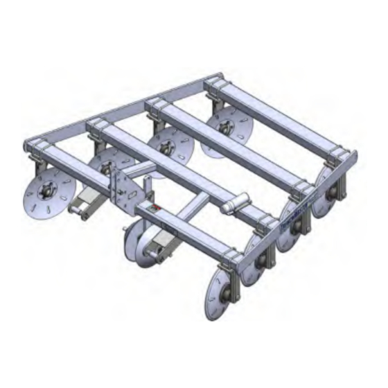
Page 15: Mounting Disc Assemblies On 4-Bar Frame
— Set Up TrenchMaster Mounting Disc Assemblies on 4-Bar Frame Using a safe lifting device and supports rated at a minimum of 1,500 lbs., place main frame on supports 36” to 42” high at each end. Using a safe lifting device rated at a minimum of 100 lbs., reposition the disc assemblies on the frame (FIG. -
Page 16: Guide Cone Stabilizer Assembly
— Set Up TrenchMaster Guide Cone Stabilizer Assembly Position the guide cone stabilizer mounting bracket weldment (JAM4772) between the 3rd link facing to the rear of the frame. Secure mounting bracket weldment (JAM4772) with 5/8”-11UNC x 7 1/2” U-bolts (JBP3331), 5/8”... -
Page 17: Guide Cone Stabilizer Hydraulic Lift Assembly Option
— Set Up TrenchMaster Guide Cone Stabilizer Hydraulic Lift Assembly Option Remove the 5/8”-11UNC x 7 1/2” U-bolts (JBP3331), 5/8” lock washers (9404-029), and 5/8”-11UNC hex nuts (9394-014) from the guide cone stabilizer hydraulic lift assembly. Using a safe lifting device rated at a minimum of 300 lbs., raise the guide cone stabilizer hydraulic lift assembly to the center of the front frame as shown in FIG. - Page 18 — Set Up TrenchMaster Guide Cone Stabilizer Hydraulic Lift Assembly Option (continued) Purging Hydraulic System • RELIEVE HYDRAULIC SYSTEM OF ALL PRESSURE BEFORE ADJUSTING OR SERVICING. SEE TRACTOR OPERATOR'S MANUAL FOR PROPER PROCEDURES. HIGH-PRESSURE FLUIDS CAN PENETRATE THE SKIN AND CAUSE SERIOUS INJURY •...
-
Page 19: Levelpro Option Assembly
— Set Up TrenchMaster LevelPro Option Assembly Using a safe lifting device rated at a minimum of 50 lbs., position offset stagger bracket weldments (JAM2394) to the rear tube of the TrenchMaster as shown in FIG. 2-6. FIG. 2-6 3" 3"... - Page 20 — Set Up TrenchMaster LevelPro Option Assembly (continued) Center the mounting plates (JAM7637) on the bottom of the offset stagger bracket weldments (JAM2394). Secure with 3/4”-10UNC x 5 11/16” U-bolts (JBP3208), 3/4” lock washers (9404-033), and 3/4”-10UNC hex nuts (9394-016) (FIG. 2-8). Torque hardware according to “Torque Chart”...
- Page 21 — Set Up TrenchMaster LevelPro Option Assembly (continued) Attach the reflectors, RED (9003126), to the torsion spring weldments (JAM4921 & JAM4922). Loosely attach the right-hand torsion spring weldment (JAM4922) to the top of the mounting plate (JAM7637) on the left-hand side with 5/8”-11UNC x 4” U-bolts (JBP3300), 5/8”...
- Page 22 — Set Up TrenchMaster LevelPro Option Assembly (continued) Using a safe lifting device rated at a minimum of 300 lbs., center the leveler coil assembly with leveler mounting plates and flange bearings in between the torsion spring weldments (JAM4921 & JAM4922). (FIG. 2-10) NOTE: The leveler coil assembly spiral must face towards the front.
-
Page 23: Inner Disc Assemblies Options
— Set Up TrenchMaster Inner Disc Assemblies Options ONE PAIR OF INNER DISC ASSEMBLIES Using a safe lifting device rated at a 100 lbs., loosely position left-hand disc assembly (JAAM4715) onto row 1 as shown in FIG. 2-11 using 3/4”-10UNC x 5 11/16” U-bolts (JBP3208) and 3/4”-10UNC lock nuts (9802). - Page 24 — Set Up TrenchMaster Inner Disc Assemblies Options (continued) TWO PAIRS OF INNER DISC ASSEMBLIES Using a safe lifting device rated at a 100 lbs., loosely position left-hand disc assembly (JAAM4715) onto row 1 as shown in FIG. 2-12 using 3/4”-10UNC x 5 11/16” U-bolts (JBP3208) and 3/4”-10UNC lock nuts (9802).
- Page 25 — Set Up TrenchMaster Inner Disc Assemblies Options (continued) THREE PAIRS OF INNER DISC ASSEMBLIES Using a safe lifting device rated at a 100 lbs., loosely position left-hand disc assembly (JAAM4715) onto row 1 as shown in FIG. 2-13 using 3/4”-10UNC x 5 11/16” U-bolts (JBP3208) and 3/4”-10UNC lock nuts (9802).
- Page 26 — Set Up TrenchMaster Notes 2-14...
-
Page 27: Operation
— Operation TrenchMaster SECTION III Operation Preparing Tractor ............................3-2 Preparing TrenchMaster ..........................3-3 Hardware .............................3-3 Pivot Pins ............................3-3 Guide Cone Stabilizer Hydraulic Lift Option Hydraulics ..............3-3 Bearings & Disc Blades ........................3-3 Lubrication ............................3-3 Attaching TrenchMaster to Tractor ......................3-4 Guide Cone Stabilizer Hydraulic Lift Option Hydraulic Hookup ............3-4 Transporting ...............................3-4 Unhitching From Tractor ..........................3-5... -
Page 28: Preparing Tractor
— Operation TrenchMaster Preparing Tractor Before operating implement refer to tractor operator’s manual for information concerning safe methods of operation, and tire inflation. Check tractor brakes and transport lights. Make sure they are in proper working order. Check tractor hydraulic oil reservoir and add oil if needed. TRANSPORTING THE IMPLEMENT SIGNIFICANTLY CHANGES THE WEIGHT AND BAL- •... -
Page 29: Preparing Trenchmaster
— Operation TrenchMaster Preparing TrenchMaster Perform the service checks as outlined. Repair or replace any damaged or worn parts before operating. Hardware Check for loose bolts and nuts, and tighten as needed. Check again after the first half-day of operation. Pivot Pins Check that all pins are in place and in good condition. -
Page 30: Attaching Trenchmaster To Tractor
Compliance with all lighting and marking laws is the responsibility of the operator at the time of travel. See federal regulation 49 CFR 562; available at www.govinfo.gov for US federal law requirements. See your Unverferth dealer for additional brackets, reflectors, or lights to meet your requirements. -
Page 31: Unhitching From Tractor
— Operation TrenchMaster Unhitching From Tractor • FALLING OR LOWERING EQUIPMENT CAN CAUSE SERIOUS INJURY OR DEATH. KEEP EVERYONE AWAY FROM EQUIPMENT WHEN RAISING OR LOWERING. • HIGH-PRESSURE FLUIDS CAN PENETRATE THE SKIN AND CAUSE SERIOUS INJURY OR DEATH. USE CARDBOARD OR WOOD TO DETECT LEAKS IN THE HYDRAULIC SYSTEM. - Page 32 — Operation TrenchMaster Notes...
- Page 33 — Maintenance TrenchMaster SECTION IV Maintenance Daily Service ..............................4-2 Beginning of Day ..........................4-2 End of Day ............................4-2 Annual Service ............................4-2 Beginning of Season ..........................4-2 End of Season ............................4-2 Lubrication ..............................4-3 Hub Assembly ............................4-3 Complete Torque Chart ..........................4-4 Hydraulic Fittings ............................4-5...
-
Page 34: Maintenance
— Maintenance TrenchMaster Daily Service Beginning of Day NOTE: Before initial use, ensure all lubrication points have been greased. Check all U-bolts and bolts for tightness. This is especially important during the first days of operation. See “Torque Chart” in this section. •... -
Page 35: Lubrication
— Maintenance TrenchMaster Lubrication • Do not use a high pressure grease gun to lubricate these bearings. Damage to bearing seals could occur. Lubricate with an SAE multi-purpose grease. All fittings must be free from dirt and paint to insure entry of lubrication inside bearing. The disc assembly hub bearing should be cleaned, repacked and adjusted once per season. -
Page 36: Complete Torque Chart
— Maintenance TrenchMaster Complete Torque Chart Capscrews - Grade 5 NOTE: • Grade 5 capscrews can be identified by three radial dashes on the head. • For wheel torque requirements, refer to Wheels and Tires. • Tighten U-bolts evenly and equally to have the same number of threads exposed on each end. -
Page 37: Hydraulic Fittings
— Maintenance TrenchMaster Hydraulic Fittings – Torque and Installation SAE FLARE CONNECTION (J. I. C.) Tighten nut with finger until it bottoms the seat. Using a wrench, rotate nut to tighten. Turn nut 1/3 turn to apply proper torque. SAE STRAIGHT THREAD O-RING SEAL Insure jam nut and washer are backed up to the back side of smooth portion of elbow adapter. - Page 38 — Maintenance TrenchMaster Notes...
-
Page 39: Parts
— Parts TrenchMaster SECTION V Parts Frame Components & Disc Assembly .......................5-2 Disc Assembly Components ........................5-4 Guide Cone Stabilizer Components (J80310014) ..................5-6 Guide Cone Stabilizer Hydraulic Lift Option (J80310035) ................5-8 LevelPro Option Components (J80310013) .....................5-10... -
Page 40: Frame Components & Disc Assembly
— Parts TrenchMaster Frame Components & Disc Assembly Please visit www.unverferth.com/parts/ for the most current parts listing. ITEM... - Page 41 — Parts TrenchMaster Frame Components & Disc Assembly Please visit www.unverferth.com/parts/ for the most current parts listing. ITEM PART NUMBER DESCRIPTION NOTES 9003126 Reflector RED, 2”x9” 9003127 Reflector AMBER, 2”x9” 900552 Manual Holder 91605 Decal, FEMA 9390-055 Capscrew, 3/8”-16UNC x 1” G5 97961 Decal, WARNING “Read and Understand”...
-
Page 42: Disc Assembly Components
— Parts TrenchMaster Disc Assembly Components Please visit www.unverferth.com/parts/ for the most current parts listing. - Page 43 — Parts TrenchMaster Disc Assembly Components Please visit www.unverferth.com/parts/ for the most current parts listing. ITEM PART NUMBER DESCRIPTION NOTES JAAM4714 Right-Hand Disc Assembly Includes Items 2-18 U-bolt, JBP3208 3/4”-10UNC x 5 11/16”, 6 13/16” C/C JAM4723 Hub Cap Strap 9802 Lock Nut/Top 3/4”-10UNC...
-
Page 44: Guide Cone Stabilizer Components (J80310014)
— Parts TrenchMaster Guide Cone Stabilizer Components (J80310014) Please visit www.unverferth.com/parts/ for the most current parts listing. ITEM 9388-1 9392-1 9394-0 9394-0 9404-0 9404-0 94981 JAM47 JAM49 JAP27 JAP27 JBP33... - Page 45 — Parts TrenchMaster Guide Cone Stabilizer Components (J80310014) Please visit www.unverferth.com/parts/ for the most current parts listing. ITEM PART NUMBER DESCRIPTION NOTES Includes Items J80310014 Guide Cone Stabilizer Assembly 1-12 9388-108 Carriage Bolt, 1/2”-13UNC x 2 1/2” G5 9392-180 Roll Pin, 3/8” Dia. x 2”...
-
Page 46: Guide Cone Stabilizer Hydraulic Lift Option (J80310035)
— Parts TrenchMaster Guide Cone Stabilizer Hydraulic Lift Option (J80310035) Please visit www.unverferth.com/parts/ for the most current parts listing. ITEM... - Page 47 — Parts TrenchMaster Guide Cone Stabilizer Hydraulic Lift Option (J80310035) Please visit www.unverferth.com/parts/ for the most current parts listing. ITEM PART NUMBER DESCRIPTION NOTES Includes Items J80310035 Guide Cone Stabilizer Hydraulic Lift Assembly 1-21 85632 Pin, 1” Dia. x 3 3/4”...
-
Page 48: Levelpro Option Components (J80310013)
— Parts TrenchMaster LevelPro Option Components (J80310013) Please visit www.unverferth.com/parts/ for the most current parts listing. Cut End Towards Front 5-10... - Page 49 — Parts TrenchMaster LevelPro Option Components (J80310013) Please visit www.unverferth.com/parts/ for the most current parts listing. ITEM PART NUMBER DESCRIPTION NOTES Includes Items J80310013 LevelPro Assembly 1-21 9390-080 Capscrew, 7/16”-14UNC x 1 1/2” G5 9390-101 Capscrew, 1/2”-13UNC x 1 1/2” G5 9394-010 Hex Nut, 1/2”-13UNC...
- Page 50 MANUALS\\J08000009//JULY 2020-1...
Need help?
Do you have a question about the BLU-JET TrenchMaster and is the answer not in the manual?
Questions and answers