
Subscribe to Our Youtube Channel
Related Manuals for Thermo Electron 3911


Summary of Contents for Thermo Electron 3911
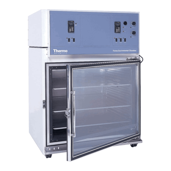
- Page 1 Models 3911 and 3913 Environmental Chamber 11 cu. ft. capacity Operating and Maintenance Manual Manual No: 7013911 Rev. 18...
- Page 2 The material in this manual is for information purposes only. The contents and the product it describes are subject to change without notice. Thermo Electron makes no representations or warranties with respect to this manual. In no event shall Thermo Electron be held liable for any damages, direct or incidental, aris- ing out of or related to the use of this manual.
- Page 3 Model 3911/3913 ________________________________________________________________________________Safety Important operating and/or maintenance instructions. Read the accompanying text carefully. Ce symbole attire l'attention de l'utilisateur sur des instructions importantes de fonctionnement et/ou d'entretien. Il peut être utilisé seul ou avec d'autres symboles de sécurité. Lire attentivement le texte d'accompagnement.
- Page 4 Model 3911/3913 ________________________________________________________________________________Service...
-
Page 5: Table Of Contents
Model 3911/3913 _____________________________________________________________________________ Contents Table of Contents Section 3 - Start Up and Operation ....3 - 1 Section 1 - Receiving ......2 - 1 1.1 Preliminary Inspection . -
Page 6: Model 3911/3913
For products shipped F.O.B. Marietta, Ohio, the responsi- ionized water should be used in the humidity reservoir. Water bility of Thermo Electron ends when the merchandise is loaded purity should be in the resistance range of 50K Ohm/cm to 1M onto the carrier’s vehicle. -
Page 7: Alternate Water Supply For Humidity System
For Model 3911, plug the provided 10 ft. power cord with A condensate pump (184062) or evaporator (1900031) is the NEMA 14-20 plug into the power outlet connection on the also available. -
Page 8: Start-Up
Model 3911/3913 ____________________________________________________________________Installation and Set-Up 2.5 Start-Up 2.7 Setting the Undertemp Safety Thermostat When the humidification system is operational, the incuba- Allow the chamber temperature and humidity to stabilize, tor may be started. Preset the controls as follows: then set the undertemp safety thermostat as follows: Overtemp Safety Thermostat . -
Page 9: Changing The Chart Paper
Model 3911/3913 ____________________________________________________________________Installation and Set-Up To prepare the recorder for operation, open the glass door 2.9 Honeywell Recorder (optional) and snap the connector onto the 9-volt battery as shown in Figure 2-3. If the unit is operating, the green LED lights steady. -
Page 10: Setting The Co
Model 3911/3913 ____________________________________________________________________Installation and Set-Up b. Setting the CO Content The Watlow 93 CO controller's upper display shows the actual CO content inside the chamber. The lower display shows the CO setpoint. Before setting the CO content, allow the chamber temper- ature and humidity to stabilize. -
Page 11: Section 3 - Start Up And Operation
Model 3911/3913______________________________________________________________________Start-Up and Operation Section 3 - Start Up and Operation Overtemp Safety Control, Indicator Light, and Audible Alarm (Figure 3-2) The overtemp safety thermostat should be set slightly above the operating temperature of the incubator. In the event of an overtemp condition, the overtemp safety ther- mostat will: •... -
Page 12: Setting The Operating Temperature
Model 3911/3913______________________________________________________________________Start-Up and Operation 3.2 Setting the Operating Temperature (Figure 3-5) Dehumidify Switch and Indicator (Figure 3-3) The dehumidify switch will enable the refrigeration The Watlow temperature system if the refrigeration switch is currently off. When controller’s upper numerical controlling humidity, the dehumidification switch should be in display shows the actual tem- the ON position for most applications. -
Page 13: Section 4 - Routine Maintenance
Model 3911/3913_______________________________________________________________________Routine Maintenance Section 4 - Routine Maintenance 4.1 Cleaning the Incubator De-energize all potential sources of energy to this unit and lockout/tagout their controls. (O.S.H.A. Regulation, Section 1910-147.) The continued cleanliness of the stainless steel used in this unit has a direct effect on the appearance and operation of the unit. - Page 14 The following is a condensed list of preventive maintenance requirements. See the specified section of the instruction manual for further details. Thermo Electron has qualified service technicians, using NIST traceable instruments, available in many areas. For more information on Preventive Maintenance or Extended Warranties, please contact us at the number below.
- Page 15 Preventive Maintenance for Model 3911/3913 Refer to Manual Section Action Daily Weekly Yearly Inspect door latch, hinges and door gasket seal Check air exchange ventilator caps for adjustment; open or close as required Perform a complete decontamination procedure. Wipe down interior, shelves, Between Experiments side panels with disinfectant.
-
Page 16: Section 5 - Service
Model 3911/3913 _________________________________________________________________________________Service Section 5 - Service 5.3 Replacing the Humidity/Temperature Sensor 1. Locate the probe mounting plate in the center of the right side of the incubator interior. 2. Open the mounting plate by removing the screws that hold it in place. -
Page 17: Removing The Software Lockout
Model 3911/3913 _________________________________________________________________________________Service Looking at the top of the Press the Mode key to scroll through the menus until the module, locate the red DIP upper and lower displays show “2 Loc” (Figure 5-5). Press the switch (Figure 5-2). With a... -
Page 18: Replacing The Optional Recorder And Probe(S)
Model 3911/3913 _________________________________________________________________________________Service 5. Remove the 982 controller module(s) by pressing in the 5. Wear a grounding wrist strap to avoid damaging any of four retaining tabs, two on the right side, two on the left the electrical components. side. Refer to Figure 5-7. Pull the controller module out 6. -
Page 19: Calibrating The Chart Recorder
Model 3911/3913 _________________________________________________________________________________Service a. Calibrating the Chart Recorder Remove all contents from the incubator, shut it off, and disconnect the power. Place an accurate thermometer(s) in the chamber next to 2. Turn off the valve supplying the sterile distilled water. -
Page 20: Co Controller Calibration
Model 3911/3913 _________________________________________________________________________________Service Figure 5-12 5.8 CO Controller Calibration This section applies to units with the 1900140 IR CO option only. If it should become necessary to calibrate the CO con- troller, perform the following procedure. 1. From the standard operating display (setpoint in bottom... - Page 21 Models 3911/3913 _______________________________________________________________________________Service WATLOW 982 CONFIGURATION RECORD CUSTOMER: JOB NUMBER: SERIAL NUMBER: CONTROL TYPE: 3911 & 3940 HUMIDITY (0 - 100%) PREPARED BY: DATE: COMPLETED BY: DATE: Switch Configuration: (1)*** Main Boards Input 1 Board Output 3 Option board Jumper switch setting:...
- Page 22 Models 3911/3913 _______________________________________________________________________________Service WATLOW 982 CONFIGURATION RECORD CUSTOMER: JOB NUMBER: SERIAL NUMBER: CONTROL TYPE: 3911 & 3940 TEMPERATURE (RTD) PREPARED BY: DATE: COMPLETED BY: DATE: Switch Configuration: (1)*** Main Boards Input 1 Board Output 3 Option board Jumper switch setting:...
- Page 23 Model 3911/3913 _________________________________________________________________________________Service WATLOW 93 CONFIGURATION RECORD CUSTOMER: JOB NUMBER: UNT SERIAL NUMBER: CONTROL TYPE: PERPARED BY: DATE COMPLETED BY: DATE: Operational Parameters: 0.05 -5.0 Setup Parameters: 4-20 20.0 Notes: * calibration offset may vary from unit to unit Important: Input switches 1&2 must be set to "on"...
- Page 24 HONEYWELL TRULINE CONFIGURATION RECORD SHT 1 OF 4 CUSTOMER: JOB NUMBER: UNIT SERIAL #: CONTROL TYPE: PREPARED BY: DATE: COMPLETED BY: DATE: GROUP FUNCTION VALUE OR GROUP FUNCTION VALUE OR PROMPT PROMPT SELECTION PROMPT PROMPT SELECTION TUNING1 PROP BD or CHART CHRTSPD 7 DAY...
- Page 25 HONEYWELL TRULINE CONFIGURATION RECORD SHT 2 OF 4 GROUP FUNCTION VALUE OR GROUP FUNCTION VALUE OR PROMPT PROMPT SELECTION PROMPT PROMPT SELECTION PEN4 PEN4 DISABLE INPUT4 DECIMAL PEN4IN UNITS CHART4HI ENGUNITS CHART4LO IN4TYPE PEN4ON XMITTER PEN4OFF IN4HI MAJORDIV IN4LO MINORDIV CUTOFF4 RNG4TAG INPTCOMP...
- Page 26 HONEYWELL TRULINE CONFIGURATION RECORD SHT 3 OF 4 GROUP FUNCTION VALUE OR GROUP FUNCTION VALUE OR PROMPT PROMPT SELECTION PROMPT PROMPT SELECTION CONTROL2 PID SETS ALARMS A1S1 VAL SW VALUE A1S2 VAL SP SOURC A1S1 TYPE NONE RATIO A1S2 TYPE NONE BIAS A1S1 HL...
- Page 27 HONEYWELL TRULINE CONFIGURATION RECORD SHT 4 OF 4 GROUP FUNCTION VALUE OR GROUP FUNCTION VALUE OR PROMPT PROMPT SELECTION PROMPT PROMPT SELECTION EVNT MSG EVENT 1 NONE MESSAGE 1 POSITION 1 EVENT 2 NONE MESSAGE 2 POSITION 2 EVENT 3 NONE MESSAGE 3 POSITION 3...
-
Page 28: Section 6 - Specifications
Model 3911/3913 _______________________________________________________________________Specifications Fittings Section 6 - Specifications Fill Port 1/8” FPT Drain Port 3/8” OD Copper Temperature Control* ±0.1°C @ +37°C (98.6°F) Unit Heat Load Range 0°C (32°F) to +60°C (140°F) 115V 5500 BTUH (1600W) Sensor 220V 6000 BTUH (1750W) -
Page 29: Section 7 - Spare Parts
Model 3911/3913 ______________________________________________________________________________Spare Parts Section 7 - Spare Parts Part No. Description 290163 RTD Temperature Sensor 230066* Fuse, Ceramic 10A 350V 290162 RH/Temp Control Signal Conditioner 400051 Power Supply 231211 Programmed Temperature Control 231212 Programmed Humidity Control 320277 Triac, 25A... - Page 32 Model 3911/3913 _______________________________________________________________________Electrical Schematics 9 - 1...
- Page 33 Model 3911/3913 _______________________________________________________________________Electrical Schematics 9 - 2...
- Page 34 Model 3911/3913 _______________________________________________________________________Electrical Schematics 9 - 3...
- Page 35 Model 3911/3913 _______________________________________________________________________Electrical Schematics 9 - 4...
- Page 36 Model 3911/3913 _______________________________________________________________________Electrical Schematics 9 - 5...
- Page 37 Model 3911/3913 _______________________________________________________________________Electrical Schematics 9 - 6...
- Page 38 Model 3911/3913 _______________________________________________________________________________________________________Electrical Schematics...
- Page 39 Model 3911/3913 _______________________________________________________________________________________________________Electrical Schematics 9 - 8...
- Page 40 Model 3911/3913 _______________________________________________________________________________________________________Electrical Schematics 9 - 9...
- Page 41 Thermo Electron Corporation Controlled Environment Equipment Millcreek Road, P.O. Box 649 Marietta, Ohio 45750 U.S.A. Telephone (740) 373-4763 Telefax (740) 373-4189...
Need help?
Do you have a question about the 3911 and is the answer not in the manual?
Questions and answers