Table of Contents
Advertisement
Advertisement
Table of Contents

Related Manuals for ITW SIMCO ION 5802i


Summary of Contents for ITW SIMCO ION 5802i
- Page 1 Critical Environment Ionizing Blower Model 5802i User’s Manual...
- Page 2 Simco-Ion Technology Group is a division of Illinois Tool Works (ITW), located in Alameda, California. For more information about Simco-Ion visit www.simco-ion.com or call 800-367-2452. Simco-Ion is ISO 9001.
- Page 3 Important Safety Information Carefully read the following safety information before installing or operating the equipment. Failure to follow these safety warnings could result in damage to your ionization system and/or voiding the product warranty. The use of improper input voltage may result in poor perfor- mance or damage to the ionizer.
- Page 4 Informations de Sécurité Importantes L'utilisation d'une mauvaise tension d'entrée peut entraîner une mauvaise perfor-mance ou d'endommager l'ioniseur. Ceci annule la garantie. Pour des raisons de sécurité, l'utilisation de cordons d'extension n'est pas recommandée. Ne pas utiliser ce ventilateur dans un environnement explosif. Mal entretenu ioniseurs pourrait produire infime arcs élec- triques au points émetteurs.
-
Page 5: Table Of Contents
Contents 1 Description ................1 1.1 Critical Environment Ionizing Blower Model 5802i........2 1.2 Blower Features..................3 1.3 Blower Options..................4 1.4 External Sensor Option................5 1.5 Performance .................... 6 1.6 Power Requirements ................7 2 Installation & Setup............. 9 2.1 Tilt Lock Mounting Stand ............... -
Page 6: Description
Description 1.1 Critical Environment Ionizing Blower Model 5802i 1.2 Blower Features 1.3 Blower Options 1.4 External Sensor Option 1.5 Performance 1.6 Power Requirements 19-5802i-M-02 Rev 4... -
Page 7: Critical Environment Ionizing Blower Model 5802I
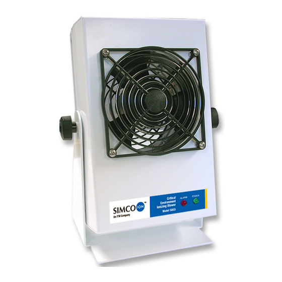
1.1 Critical Environment Ionizing Blower Model 5802i The Critical Environment Ionizing Blower Model 5802i is a fast and reliable ionizing Blower for controlling static charge in desktop work areas and small spaces in critical areas. The Model 5802i achieves an offset balance of ±3V or better than ±1V offset balance with an optional external sensor connected. -
Page 8: Blower Features
1.2 Blower Features The Model 5802i is offered in an epoxy-polyester powder-coated aluminum or plain finish stainless steel chassis. Several other feature configurations are available to suit your environment. Controls and connectors are located on the back of the Blower. The following features are standard, as shown below: 1. -
Page 9: Blower Options
1.3 Blower Options In addition to the standard features, several options are available with the Model 5802i to fit the needs of your environment. Your unit may include: • Stainless steel chassis • Collimator • Locking mounting stand • Wall stand •... -
Page 10: External Sensor Option
1.4 External Sensor Option The Model 5802i ionizer can operate with a Novx Series 7000, 3350 or 3360 to detect and automatically correct the offset balance. The sensor antenna is placed at the target and feedback is sent to the Model 5802i’s internal control system. Novx Passive/Active Novx Process Monitor Detection System... -
Page 11: Performance
1.5 Performance The Model 5802i is factory adjusted to meet the specifications described below. However, performance in different environments may vary. After installation, the Blower should be adjusted in the operating environment for optimum performance. For instructions, refer to the Balance Adjustment section of this manual. The Model 5802i has a typical static discharge time of two seconds or less directly in line with the center of the fan (±1000V to 100V). -
Page 12: Power Requirements
1.6 Power Requirements The use of improper input voltage may result in poor performance or damage to the Blower. This will void the warranty! For safety, the use of extension cords is not recommended. The Model 5802i is powered by a DC power supply (Simco-Ion P/N 14-1115-SAC-01). - Page 13 19-5802i-M-02 Rev 4...
-
Page 14: Installation & Setup
Installation & Setup 2.1 Tilt Lock Mounting Stand 2.2 Cord Lock Installation Option 2.3 Cord Clamp Installation 2.4 Ground Jack Use 2.5 Sensor Connections & Setup Option 2.6 FMS Connection Option 19-5802i-M-02 Rev 4... -
Page 15: Tilt Lock Mounting Stand
2.1 Tilt Lock Mounting Stand The Model 5802i is supplied with a tilt-adjustable locking stand. For all types of mounting stands, aim the Blower so that its airflow will travel as directly as possible to your target. Tilt Locking Stand Adjustment To adjust the tilt stand, loosen the side knobs on the Blower and adjust the Blower in the appropriate direction. -
Page 16: Cord Lock Installation Option
2.2 Cord Lock Installation Option If your Model 5802i includes a cord lock, the cord lock bracket will arrive uninstalled with the Blower. To install the cord lock: 1. Make sure the power supply is not connected to power. 2. Remove the screw below the power input and set aside. -
Page 17: Cord Clamp Installation
2.3 Cord Clamp Installation The cord clamp arrives uninstalled with the Blower. To install the cord clamp: 1. Disconnect the DC power supply from AC line power. 2. Remove one of the lower screws of the rear finger guard. Do not open the chassis or remove the rear finger guard from the chassis. -
Page 18: Ground Jack Use
2.4 Ground Jack Use The ground jack offers a convenient, built-in connection for optional grounding of test equipment. A standard banana-type plug is used to connect to the jack. A ground connection through this jack is not required for the proper operation of the Model 5802i. -
Page 19: Sensor Connections & Setup Option
2.5 Sensor Connections & Setup Option Sensor Types The type of sensor used will depend on your application needs. Simco-Ion publishes a product bulletin that recommends approved sensor types, setup, maintenance and positions. For the best performance results, please use the information in the product bulletin to select an appropriate sensor. - Page 20 Figure 7. Sensor Input Pinout Designations Placement and Mounting Placement of the external sensor is critical to maintaining a ±1V balance. Place the sensor or antenna as close to the target as possible while still remaining in the ionized air stream. To Connect the Novx Series 7000 In addition to the connections in Table 1, make the following connections:...
- Page 21 Figure 8. Power and Sensor Connections Sensor Setup and Verification If you use an external sensor with the Model 5802i, you will need to carefully adjust the sensor and Blower to obtain optimal balance performance. The following steps apply to the Novx Series 7000, Novx Series 3350/60 or Novx Series 3150.
- Page 22 1. Make sure the wiring connections are made as shown in Tables 2 and 3. 2. Set both Mode DIP switches on the Model 5802i Control Box to the down position, the “Sensor Off” mode is for testing. 3. Verify that the Gain trimpot on the Control Box is set to approx- imately 1/2 (factory default).
- Page 23 10. On the sensor mode DIP switch on the 5802i, set switch #1 to the up position (ON) and switch #2 to the down position (Servo 0) for Novx sensor operation. 11. Turn on the Blower. Note the offset voltage settles within ±1V of zero and no alarm is indicated.
-
Page 24: Fms Connection Option
2.6 FMS Connection Option Your unit may feature the optional 4-20 mA current loop RJ-11 receptacle interface for connection to a facility monitoring system (FMS). The FMS output provides the following condition states: State Signal at Connector No power applied 0 mA Normal status 4 mA... - Page 25 Novx Series 7000 Connect From Connect To Interface Cable Novx 4-20 mA to 10 pin 5802i Modular jack Novx Series 7000 "AUX" Decoder (p/n 33-7000-x) labeled "FMS OUT" Novx Series 3350/ Connect From Connect To 3360 Interface Cable Novx 4-20 mA to 10 pin 5802i Modular jack Novx Series 3350/3360 "DI/O"...
-
Page 26: Operation
Operation 3.1 Operating Environment 3.2 Turning on the Blower 3.3 Balance Adjustment 3.4 Optional Sensor Operation 3.5 Alarms 19-5802i-M-02 Rev 4... -
Page 27: Operating Environment
3.1 Operating Environment Do not use this Blower in an explosive environment. Poorly maintained Ionizers could produce miniscule electric arcs at the emitter points. This may cause detonation in an Warning: explosive environment. Read the Power Requirements section in Chapter 1 and the Operating Environment section in this chapter before applying power to the unit. -
Page 28: Turning On The Blower
3.2 Turning on the Blower Fan Speed Selection Before you plug in the Blower, set the sensor on/off switch to Sensor Off. For accurate readings, allow the Blower to operate for a warm-up period of 3-5 minutes before making a final balance adjustment prior to performing delay time or offset balance testing 1. -
Page 29: Balance Adjustment
3.3 Balance Adjustment These instructions are for use by qualified maintenance personnel only. To avoid personal injury or damage to the Caution: equipment, do not perform any maintenance other than that contained in these instructions. Ces instructions sont à utiliser par le personnel de maintenance qualifié... - Page 30 2. If a sensor is installed, slide the sensor on/off switch to Sensor Off. Disconnect the sensor input cable from the Blower. 3. Using a small screwdriver or trimpot tool, carefully adjust the Balance Adjustment Control on the Model 5802i until the offset balance voltage at the CPM reads 0 (±3V).
-
Page 31: Optional Sensor Operation
3.4 Optional Sensor Operation If your Model 5802i features a sensor input connector and you are not operating a sensor with your Blower, make sure the sensor on/off switch is set to Sensor Off. See Chapter 2 for information on connecting a sensor for units with the sensor input option. - Page 32 Due to the operating differences between sensors, it is always best to perform a physical disconnection/reconnection of the sensor input cable while performing discharge verification testing. Do not use the sensor on/off slide switch for this function. 1. Use a small flatblade screwdriver to slide the sensor on/off switch to Sensor Off.
-
Page 33: Alarms
3.5 Alarms The red alarm LED, located on the front panel of the Blower, lights up in the event of an alarm condition. If your Blower features an optional audible alarm, it will also sound. It is normal for the alarm LED to momentarily flash on and then off upon initial power up of the Blower. -
Page 34: Maintenance
Maintenance 4.1 Maintenance Scheduling 4.2 Emitter Point Inspection & Cleaning 4.3 Using the Auto-Clean System Option 4.4 Emitter Ring Cleaning 4.5 Fan & Finger Guard Cleaning 4.6 Chassis Cleaning 4.7 Troubleshooting 19-5802i-M-02 Rev 4... -
Page 35: Maintenance Scheduling
4.1 Maintenance Scheduling The Model 5802i is designed to be maintained primarily by internal feedback circuitry. It requires no user maintenance other than periodic cleaning of the emitter points, case, and fan. Simco-Ion recommends cleaning the emitter points once a week for critical applications or once a month for normal maintenance. -
Page 36: Emitter Point Inspection & Cleaning
4.2 Emitter Point Inspection & Cleaning • Use cleanroom-compatible cleaning cloths • Use cleanroom-compatible cloth swabs (polyester cloth is recommended) • Use cleaning solution of 50% IPA (electronic-grade isopropanol alcohol)/50% de-ionized water • Use Clean dry air (CDA) Periodically inspect emitter points for signs of point breakage, buildup on the tips, or other notable degradation of the emitter tip. -
Page 37: Using The Auto-Clean System Option
4.3 Using the Auto-Clean System Option The Auto-Clean System features a brush mechanism that sweeps the emitter points when the blower is turned off and on, removing particles from emitter points. To use the Auto-Clean System: 1. Remove any contamination-sensitive objects around the blower. -
Page 38: Emitter Ring Cleaning
4.4 Emitter Ring Cleaning If the emitter ring is dirty, the alarm may light, even when the blower provides accurate discharge times. If you have the optional audible alarm, it will sound when an alarm condition occurs. To clean the emitter ring: 1. -
Page 39: Fan & Finger Guard Cleaning
4.5 Fan & Finger Guard Cleaning First clean both the fan blades and the finger guard with clean, dry compressed air. It is not necessary to remove the fan guard to blow- off the fan blades with compressed air. Moisten a cleanroom cloth with the diluted 50% IPA solution. Thoroughly wipe down the exposed surfaces of the stainless steel sensor grill particularly the mounting eyelets, to remove any accumulated dirt on the mounting screws or isolating washers. -
Page 40: Chassis Cleaning
4.6 Chassis Cleaning Moisten a cleanroom cloth with the diluted 50% IPA solution. Thoroughly wipe down the case to remove any accumulated dirt. Change the cloth frequently to make sure the dirt is completely lifted. 19-5802i-M-02 Rev 4... -
Page 41: Troubleshooting
4.7 Troubleshooting The table below provides a quick troubleshooting reference for the Model 5802i. If any of the solutions listed do not remedy the problem, contact Simco-Ion Technical Support (techsupport@simco-ion.com or 510-217-0470). Problem Possible Cause Solution Check fan guards for any Fan is noisy or slow Fan is obstructed obstructions... -
Page 42: Specifications
Specifications 5.1 Specifications 5.2 Replacement Parts & Accessories 19-5802i-M-02 Rev 4... - Page 43 5.1 Specifications Model 5802i Ionizer Input Voltage 24 VDC; 470 mA (max) Output Voltage ±5-6 kV (typ); 6-7 µA emitter current (typ) Balance Better than ±1V typ with external sensor; ±3V typ without sensor With collimator, 1 sec. or less in line with center of fan at 1 ft. away; Discharge without collimator: 2 sec.
- Page 44 5.2 Replacement Parts & Accessories Contact your Simco-Ion representative or Simco-Ion Sales Services department for more information about these replacement parts. Simco-Ion P/N Description 14-1115-SAC-01 100-240 VAC to 24 VDC power supply 22-1000 Emitter Point Cleaner solution 22-0356 Class 1 titanium emitter points 25-20660 US plug power cable, 8.2 ft (2.5m) 25-0670...
- Page 45 19-5802i-M-02 Rev 4...
-
Page 46: Warranty & Service
Warranty & Service Simco-Ion provides a limited warranty for the Critical Environment Ionizing Blower Model 5802i. New products manufactured or sold by Simco-Ion are guaranteed to be free from defects in material or workmanship for a period of two (2) years from date of initial shipment. - Page 47 Notes 19-5802i-M-02 Rev 4...
- Page 48 Technology Group 1601 Harbor Bay Pkwy, Ste 150 Alameda, CA USA 94502 Tel: 510-217-0600 Fax: 510-217-0484 Toll free: 800-367-2452 Sales services: 510-217-0460 Tech support: 510-217-0470 info@simco-ion.com salesservices@simco-ion.com techsupport@simco-ion.com service@simco-ion.com www.simco-ion.com 19-5802i-M-02 Rev 4...
Need help?
Do you have a question about the SIMCO ION 5802i and is the answer not in the manual?
Questions and answers