Table of Contents
Advertisement
Quick Links
Advertisement
Table of Contents

Related Manuals for ITW ION SYSTEMS 6432e


Summary of Contents for ITW ION SYSTEMS 6432e
- Page 1 Point of Use Ionizing Blower Model 6432e User’s Manual...
- Page 2 About ION Systems ION Systems, an ITW Company develops, manufactures, and markets system solutions to manage electrostatic charge. As the world's largest provider of electrostatics management products and services, ION Systems improves its customers' business results by providing a total solution to their electrostatic discharge and electromagnetic interference challenges.
-
Page 3: Table Of Contents
Contents 1 Description...............1 1.1 Point of Use Ionizing Blower Model 6432e ........... 2 1.2 About IsoStat Technology ..............4 1.3 Performance ..................5 1.4 Power Requirements ................6 2 Set Up & Operation............7 2.1 Box Contents..................8 2.2 Mounting Stand Installation and Placement ........10 2.3 Mounting Stand Knob Replacement.......... -
Page 4: Description
Description 1.1 Point of Use Ionizing Blower Model 6432e 1.2 About IsoStat Technology 1.3 Performance 1.4 Power Requirements 19-6432-M-01 Rev 1... -
Page 5: Point Of Use Ionizing Blower Model 6432E
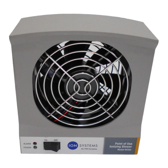
1.1 Point of Use Ionizing Blower Model 6432e The Point of Use Ionizing Blower Model 6432e controls static discharge in areas where static build-up can cause contamination, ESD, material-handling problems, or microprocessor lock-up. The internal emitter points are electrostatically shielded to eliminate field-induced charging. - Page 6 Figure 2. Back of Model 6432e Blower 19-6432-M-01 Rev 1...
-
Page 7: About Isostat Technology
1.2 About IsoStat Technology Patented IsoStat technology makes ION Systems ionizing Blowers the most reliable ionizers available. IsoStat enables them to operate without grounding wires or cables and still maintain ionizer balance. The Model 6432e Blower’s internal emitter points are electrostatically shielded to eliminate field-induced charging. -
Page 8: Performance
1.3 Performance The Blower will reduce a static charge of ±1,000V down to ±100V in approximately 4 seconds at a distance of 1 ft. (30.48 cm). See the table below for typical discharge times as determined by distance. Distance is measured from the front center of the Blower. Ionization balance is better than ±20V at 1 ft. -
Page 9: Power Requirements
1.4 Power Requirements The Model 6432e Blower can receive power from four different sources. Three different power supplies are available as options for the Blower, providing 24 VDC or 24 VAC. The fourth power source for the Blower is 24 VDC from your process equipment using the terminal block and eight pin connector on the rear of the Blower. -
Page 10: Setup & Operation
Setup & Operation 2.1 Box Contents 2.2 Mounting Stand Installation and Placement 2.3 Mounting Stand Knob Replacement 2.4 Blower Placement 2.5 Power Connections 2.6 FMS Connection 2.7 Turning on the Blower 2.8 Alarms 19-6432-M-01 Rev 1... -
Page 11: Box Contents
2.1 Box Contents The Blower is supplied with: • Two round mounting stand knobs. • Two truss-head screws for securing the bracket (p/n 28-3328). • One 8-pin terminal block plug for connecting to tool power (p/n 18-2308). • Certificate of Compliance. In addition, the following options may be included if they have been ordered: •... - Page 12 Figure 3. Mounting Stand Knobs, Screws, and 8-pin Terminal Block 19-6432-M-01 Rev 1...
-
Page 13: Mounting Stand Installation And Placement
2.2 Mounting Stand Installation and Placement Two mounting stands are available with the Blower. • Benchtop • In-tool Benchtop Stand Figure 4. Benchtop Stand 1. Fasten the Blower to the mounting stand using the molded knobs supplied with the chassis. 2. - Page 14 In-tool Stand 1. Fasten the Blower to the mounting stand using the molded knobs supplied with the chassis. 2. To adjust the benchtop stand, loosen the side knobs on the Blower and adjust the Blower to the appropriate angle. 3. Re-tighten the knobs to secure the Blower in place.
- Page 15 Figure 6. In-tool Bracket--Mounting Hole Locations on Underside of Bracket 19-6432-M-01 Rev 1...
-
Page 16: Mounting Stand Knob Replacement
2.3 Mounting Stand Knob Replacement The standard knobs on the mounting stand may be replaced with the truss head screws that are packaged with the Blower if desired. The screws allow for an improved grip on the mounting stand as they can be tightened down using a standard Phillips screwdriver. -
Page 17: Blower Placement
2.4 Blower Placement Place the Model 6432e Blower in the desired in-tool or benchtop location. (See Table 1 on page 5 for discharge time distance recommendations.) Caution: Do not use this Blower in an explosive environment. Poorly maintained ionizers could produce minuscule electric arcs at the emitter points. -
Page 18: Power Connections
2.5 Power Connections The Blower may be powered by an optional 24 VAC 120 or 220 volt transformer or a 24 VDC universal AC adapter, sold separately by ION Systems. Plug the transformer or universal AC adapter into a properly grounded VAC receptacle with the correct voltage for your power supply. - Page 19 Process Equipment Power Connection Two pins on the eight-pin terminal strip on the rear of the Blower can receive 24 VDC power from your process equipment. An included terminal block (ION Systems p/n 18-2308) is used to connect 24 VDC power to the Blower from your process equipment.
- Page 20 Figure 10. Connected Terminal Block Caution: Damage to the product as a result of improper wiring connections or failure to heed maximum voltage limits will not be covered by the warranty. Achtung: Schäden am Produkt infolge unsachgemäßer Verdrahtung oder wegen unterlassener Beachtung von maximal zulässigen Spannungen werden nicht durch die Garantie abgedeckt.
-
Page 21: Fms Connection
2.6 FMS Connection The Model 6432e Blower provides a non-isolated 4-20 mA current loop and relay closure output for indicating alarm status to your process equipment or facility monitoring system (FMS). In addition to connecting 24 VDC power to the Blower, the included terminal block (ION Systems p/n 18-2308) connects the Blower to the FMS using pins 1-5. -
Page 22: Turning On The Blower
2.7 Turning on the Blower Use the on/off switch on the front of the unit to turn on the Blower. The green Power LED will light. Once the Blower is powered on, its position may be readjusted to achieve optimum discharge time within the air pattern of the Blower. -
Page 23: Alarms
2.8 Alarms In the event of an alarm, the red LED on the front of the Model 6432e Blower will light. An alarm indicates that the Blower’s internal high voltage power circuitry that drives the emitter points is not functioning correctly. Causes may include low or incorrect input voltage, or a compromised internal part. -
Page 24: Maintenance
Maintenance 3.1 Maintenance Requirements 3.2 Cleaning the Chassis 3.2 Cleaning the Chassis 3.3 Cleaning the Emitter Points 19-6432-M-01 Rev 1... -
Page 25: Maintenance Requirements
3.1 Maintenance Requirements The performance of the Blower is designed to be maintained primarily by the internal auto-balance circuitry. Occasional cleaning of the case and emitter points is the only routine maintenance required. No readjustment of the ionizer is required after cleaning. -
Page 26: Cleaning The Chassis
3.2 Cleaning the Chassis Moisten a cloth with the IPA solution. Wipe off any dirt that may have accumulated on the unit. 19-6432-M-01 Rev 1... -
Page 27: Cleaning The Emitter Points
3.3 Cleaning the Emitter Points Caution: Before performing any maintenance on emitter points, remove the power plug from the ionizer. Allow a minute for the high voltage power supply to discharge. Achtung: Ziehen Sie vor der Durchführung von Wartungsarbeiten an Emitter-Punkten den Netzstecker aus dem Ionisator. -
Page 28: Specifications
Specifications Model 6432e Blower Power Input 24 VDC (±10%), 6W max or 24 VAC (±10%); 50/60 Hz, 6W max Ion Emission Steady-state DC Emitter Points Tungsten wire; internally shielded; 5-year life ±1000-100V, <4 sec @ 1 ft. (using 24 VAC), tested in accordance Discharge with ANSI/ESD STM3.1-2000 Airflow... - Page 29 Temperature 0-40°C (32-104°F) Operating Humidity 0 to 95% without condensation The power supply is provided with protection against short circuit Short Circuit Protection by means of a primary thermal fuse. Dimensions 2.4H x 2.2W x 1.6D in. (6.1 x 5.6 x 4.1 cm) Weight 9.5 oz (269g) Certifications...
- Page 30 Two truss head screws for replacement of mounting stand knobs Optional Stand Screws (both In-tool and Benchtop); included with blower Tilt Adjustable Yes (both in-tool and benchtop) 19-6432-M-01 Rev 1...
- Page 31 Figure 12. Blower with Benchtop Stand 19-6432-M-01 Rev 1...
- Page 32 Figure 13. Blower with In-tool Stand 19-6432-M-01 Rev 1...
- Page 33 19-6432-M-01 Rev 1...
-
Page 34: Warranty & Service
Warranty & Service ION Systems provides a limited warranty for the Point of Use Ionizing Blower Model 6432e. New products manufactured or sold by ION Systems are guaranteed to be free from defects in material or workmanship for a period of two (2) years from date of initial shipment. - Page 35 19-6432-M-01 Rev 1...
- Page 36 Notes 19-6432-M-01 Rev 1...
- Page 37 Notes 19-6432-M-01 Rev 1...
- Page 38 1750 North Loop Road Alameda, CA USA 94502 Tel: 510-217-0600 Fax: 510-217-0484 Toll free: 800-367-2452 Sales services: 510-217-0460 Tech support: 510-217-0470 info@ion.com salesservices@ion.com techsupport@ion.com service@ion.com www.ion.com 19-6432-M-01 Rev 1...
Need help?
Do you have a question about the ION SYSTEMS 6432e and is the answer not in the manual?
Questions and answers