
Related Manuals for TSI Instruments CA-CALC 6203 Series


Summary of Contents for TSI Instruments CA-CALC 6203 Series
- Page 1 C o m b u s t i o n A n a l y s i s Model 6203 Series CA-C Combustion Analyzers Operation and Service Manual P/N 1980472 Revision – October 2002...
- Page 3 Model 6203 Series CA-C Combustion Analyzers Operation and Service Manual October 2002 P/N 1980472 Revision - SHIP/MAIL TO: E-Mail TSI Incorporated answers@tsi.com Attn: Customer Service 500 Cardigan Road WEB SITE Shoreview, MN 55126 www.tsi.com U.S. and CANADA INTERNATIONAL Sales and Customer Service: Sales and Customer Service: (800) 874-2811/(651) 490-2811 (001 651) 490-2811...
- Page 4 Copyright © TSI Incorporated / 2002 / All rights reserved. Part Number 1980451 / Revision - Address TSI Incorporated / 500 Cardigan Road / Shoreview, MN 55126 / USA Fax No. (651) 490-3824 LIMITATION OF WARRANTY AND LIABILITY (effective July 2000) Seller warrants the goods sold hereunder, under normal use and service as described in the operator's manual, shall be free from defects in workmanship and material for twenty-four (24) months, or the length of time specified in the operator's manual, from the date of shipment to the...
-
Page 5: Table Of Contents
CONTENTS Chapters Introduction ..................1 Manual Purpose ................1 Using This Manual................. 1 Warnings and Cautions ..............1 Instrument Description ............... 3 CA-C 6203 Measurements and Calculations......3 Unpacking ..................5 List of Standard Components............5 Accessories and Replacement Parts ..........5 Component Identification ............ - Page 6 Printing to the Portable Printer and to a Computer .....24 Handling Data ................27 MENU Options................29 BASE.L MENU—Option Update Sensor Baselines ....30 FUEL MENU Option—Select Fuel ..........30 FP MENU Option—Fuel Parameters ..........31 UNITS MENU Option (changing units)........31 INT.SA MENU Option—Sampling Interval for Saving Data ..31 TIME MENU Option—Set Time and Date for Printout ....32 CALIB MENU Option (select sensor for calibration) ....32 Gas Sensor Calibration ............33...
- Page 7 A General Equation for the Combustion of a Simple Hydrocarbon in Air ..............54 Calculating CO Max From the Carbon Content ......54 Calculation of Combustion Air Requirement ....... 54 Series CA-6203 CA-C Combustion Analyzer Specifications ................55 Default Settings For Different Model Letter Designations ..57...
-
Page 9: Introduction
Introduction Manual Purpose This manual describes the operation and maintenance of TSI CA-C CA-6203 portable combustion analyzer. Using This Manual Before using your CA-C combustion analyzer, review this manual in its entirety. Warnings and Cautions The manual assumes that you have a basic understanding of combustion safety and are thoroughly familiar with the fuel burning equipment being tested. -
Page 11: Instrument Description
Chapter 1 Instrument Description The CA-C combustion analyzer, Model CA-6203 is used to evaluate the performance of burners in boilers, furnaces, and hot water tanks. The Model CA-6203 has sensors for the direct measurement of combustion gases; O , CO, NO; combustion gas temperatures and draft pressure. The CA-6203 performs a complete list of combustion and emission parameters for a variety of system performance evaluations. - Page 12 The CA-C 6203 stores individual data samples (up to 100), and prints the data to a portable printer or computer. Stored data can be saved over a user-defined interval and averaged. The CA-C 6203 has a variety of standard fuels, and enables you to modify the fuel parameters, or install your own user-defined fuel.
-
Page 13: Unpacking
Chapter 2 Unpacking Carefully unpack your CA-C combustion analyzer and accessories from the carrying case. Check the individual parts against the list of components in the table below. If items are missing or damaged, notify TSI immediately. List of Standard Components Qty. -
Page 15: Component Identification
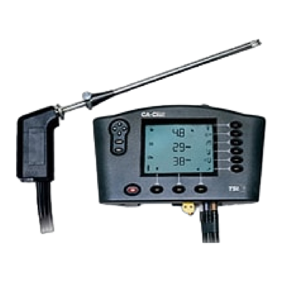
Chapter 3 Component Identification Key components of the CA-C combustion analyzer and sampling probe are identified in Figures 1 and 2, and under section headings in the text that follows. 1. Bottom buttons 9. Battery cover 2. LCD display 10. Battery cover tab 3. -
Page 16: The Gas Sensors
1. Tube retaining fitting 6. Thermocouple connector 2. Probe handle 7. Flexible sample line 3. Position collar 8. Water Trap 4. Sample tube 9. Water trap filter 5. Probe tip with thermocouple Figure 2: CA-C Sampling Probe Components The Gas Sensors The CA-CALC CA-6203 uses three gas sensors for measuring oxygen (O carbon monoxide (CO) and nitric oxide (NO). -
Page 17: The Sampling Probe
The Sampling Probe Your combustion analyzer comes equipped with a sampling probe, depicted in Figure 2. A thermocouple extends to the end of the sampling tube for making flue temperature measurements. Two flexible sampling lines are used for gas sampling and draft measurement. The sampling tube is removable for cleaning. -
Page 18: Schematic Representation Of Ca-Calc
Schematic Representation of CA-C Figure 3. Schematic Representation of CA-C Chapter 3... -
Page 19: Getting Started
Chapter 4 Getting Started Supplying Power The CA-C portable combustion analyzer operates using 4 C batteries or an AC adapter. Quality alkaline batteries enable the instrument to operate for at least 24 hours. Use of the plug-in AC adapter conserves battery life, and can be substituted for batteries. -
Page 20: Connecting The Optional Combustion Supply Air Temperature Probe
Sample Connector (Brass) Thermocouple Connector Draft Connector (Silver) Figure 4: Sampling Probe Connections Connecting the Optional Combustion Supply Air Temperature Probe A type K thermocouple probe may be used to measure the temperature of the air supplied to the burner. Connect the optional supply air thermocouple (see “Accessories and Replacement Parts”) to the supply air thermocouple port depicted in Figure 1. -
Page 21: Default Instrument Settings
large 9-pin connector on the computer interface cable to the 9-pin serial connector on your computer. Connect the opposite end to the instrument’s RS232 communications and printer port. See Figure 1 for port location. Set the baud rate of the CA-C to that of your computer, as described in Chapter 6, “MENU Options.”... -
Page 23: Basic Operation
Chapter 5 Basic Operation Buttons and Button Operations ON-OFF Control Button Turns the instrument on and off. The ENTER Control Button Press the ENTER button to execute a command, such as selecting a menu item. The ESC Control Button Used to return to the previous screen or cancel a process. ARROW Control Buttons Use the Left and Right arrow buttons to step between options. -
Page 24: Startup
Bottom Buttons Clear stored data Review stored data Save data Startup Remove the sampling probe from the flue or disconnect the sample tubing from the sampling port. Press the ON-OFF button. Refer to Figure 5 showing screens displayed during the start up sequence. If no errors are detected, the Main Data Display screen appears when the sequence is complete. - Page 25 Model Number Serial Number Error Codes Time and Date Version Number Warm-up Countdown Main Data Display Figure 5. Startup Sequence Basic Operation...
-
Page 26: Characters And Display Icons
Characters and Display Icons Refer to Figures 6 and 7 that follow. These identify the icons and characters found on the Model 6203 display. The display icons indicate measurements made, units, or functions performed. Some icons are not used with the Model CA-6203. - Page 27 Oxygen Average of samples Sample number Carbon monoxide Nitric oxide NO undiluted Draft CO undiluted Pounds / million Btu Supply air temperature lb/MBtu η ng/J Efficiency (Siegert) Nano grams / Joule Parts per million Efficiency (ASME) mg/m Carbon Dioxide Milligrams / M Menu Hecto Pascals MENU...
-
Page 28: Measurements And Calculations
Measurements and Calculations Oxygen Measurement An O electrochemical sensor measures oxygen concentration in the range of 0 to 25%. The O measurement is also used to calculate the concentration of carbon dioxide (CO in the exhaust, and is used in calculations of combustion efficiency and undiluted CO and NO concentrations. - Page 29 Efficiency Combustion efficiency, expressed as a percent. Calculated as 100 percent minus ASME heat loss (Loss) described earlier. Also see Appendix B. ŋ Siegert Efficiency Combustion efficiency, expressed as a percentage. Calculated as 100 percent minus qA. Also refer to Appendix B. , Undiluted Carbon Monoxide Concentration Calculation of the CO concentration, undiluted by excess air.
-
Page 30: Data Display, Viewing Measurements And Calculations
Data Display, Viewing Measurements and Calculations Measurements and calculations are presented in the Data Display screens. The Data Displays appear once the Startup sequence is complete (illustrated earlier in Figure 5). Data appears on three lines, with an icon indicating the measurement or calculation presented above or to the left of the data. - Page 31 To ensure that the gas measurements are not diluted or cooled by outside air, place the probe before any draft damper or regulator as illustrated in Figure 8. Tilt the probe tip up slightly so vapor condensing in the sampling tube does not run back to the probe tip and cool the thermocouple tip.
-
Page 32: Making A Draft Measurement
Cautions Hot probe! When removed, the sampling probe will be extremely hot. Avoid touching the probe tip, and avoid placing the probe on or near plastic materials such as the instrument case. These will melt. Maintain a minimum 2” (5 cm) clearance between the probe handle and position collar when the probe is mounted in flue. - Page 33 To print the information on the Data Display, press the PRINT button, to the right of the print button icon. The printer responds immediately, producing a printout of the current data. An example of this printout is shown in Figure 9. Saved data can be printed too.
- Page 34 -------------------------------- MODEL: 6203 SERIAL: ---------------------------------- Current Data --------------------------------- DATE: 01/01/99 TIME: 15:00:18 Fuel: Nat Gas Fuel Parameters: C: 75 H: 25 CO2MX: 11.8 KBTU: 23.8 H2O: 0 5 PPM 0 PPM 7 PPM 40 PPM 56 PPM 42 PPM 70 °F 300 °F Draft 0.01 inH2O...
-
Page 35: Handling Data
Handling Data Saving Data Up to one hundred (100) separate measurements can be made and saved to the instrument memory as data Samples. Press the SAVE DATA button located below the SAVE DATA icon at the bottom of the display. When SAVE DATA is pressed, measurements are sampled and averaged over the interval set in the INT.SA MENU option described in Chapter 6. -
Page 37: Menu Options
Chapter 6 MENU Options The Series 6203 CA-C instrument has a variety of user selectable parameters, available as MENU options. The user-selectable MENU options are shown in the schematic below. Press ENTER to access the MENU options from the Main Data Display screen. View the MENU options by using the ARROW buttons. -
Page 38: Base.l Menu-Option Update Sensor Baselines
BASE.L MENU—Option Update Sensor Baselines Use the BASE.L MENU option to update the zero concentration baselines for your electrochemical sensors. Make sure the sampling probe is removed from the flue or disconnected from the instrument during zeroing. If ESC is pressed before zeroing is complete, previous baseline values are restored. -
Page 39: Fp Menu Option-Fuel Parameters
FP MENU Option—Fuel Parameters See later. UNITS MENU Option (changing units) It is possible to display data in different measurement units as indicated in the table below. Optional Units Measurement UNIT Options TEMP (temperature) Degrees F, Degrees C GAS (for CO, NO, NO PPM, mg/m , lb/Mbtu, ng/J concentrations) -
Page 40: Time Menu Option-Set Time And Date For Printout
TIME MENU Option—Set Time and Date for Printout Press the ENTER button when the TIME MENU item is displayed. Use the ARROW buttons to select the field to be changed. The field will blink as it is changed with the right and left ARROW button. To change the value, use the up and down ARROW buttons. -
Page 41: O 2 Gas Sensor Calibration
Gas Sensor Calibration The Oxygen (O ) sensor is SPAN calibrated in room air whenever the instrument is turned on and allowed to complete the Startup sequence. Using the BASE.L MENU option also spans the O sensor. Additional calibration is generally not required. Calibrating the O sensor is done to determine a new zero value (no O present) for the sensor. -
Page 42: Draft Calibration
Note: It is possible to do only the CO part of the calibration. To bypass the calibration using the combined CO and H bottle, press the ESC key after the CO portion of the calibration is complete. CAUTION Toxic Gases! Familiarize yourself with the toxic properties of the calibration gases by reading the supplied Material Safety Data Sheets (MSDS) accompanying the gas... -
Page 43: Temperature Calibration
Temperature Calibration Calibration of the flue and ambient thermocouple sensors is not recommended. Thermocouples are very repeatable, and even if replacement of a sampling probe is required, or a combustion air temperature probe is purchased as an accessory, it is unnecessary to calibrate it. Thermocouple accuracy can be improved for a specific temperature range if a calibration is preformed in that range. -
Page 44: No Sensor
Use the ARROW buttons to find the CAL.FA MENU option. Press the ENTER button. CO icon Choose the CO icon using the ARROW keys and press ENTER. Use ARROW buttons to change AVAL, BVAL, CVAL and DVAL calibration factors. Press the ENTER after changing each value. -
Page 45: Baud Rate Menu Option
BAUD Rate MENU Option Baud rate can be set to match your computer or portable printer. Your instrument is delivered with a default baud rate of 1200 to match the printer. Baud rate values are displayed in the BAUD rate MENU option divided by 1000. - Page 46 Press ENTER button from the Data Display screen. Find FP using the ARROW buttons Press ENTER to access the fuel parameter list. Find the parameter to change using the ARROW buttons Change the parameter value using the ARROW buttons. Press the ENTER button to accept the new value Press ESC to abort.
- Page 47 Refer to the diagrams below (Figures 24 and 25), for information on viewing and changing fuel parameters. Your CA-C has parameters for seven common U.S. fuels in instrument memory. Fuel parameters for these fuels can be changed, if you know, for example, that your fuel has a different composition than that stored.
- Page 48 The default Siegert coefficient values in your CA-C , are those used in Germany. Siegert coefficients used in other countries may be different, reflecting differences in local fuel compositions. Figure 25 diagrams the steps in changing the Siegert fuel parameters. Figure 14.
-
Page 49: Setup For Gas Calibration
Chapter 7 Setup for Gas Calibration The Calibration Setups Note: To perform your gas sensor calibration, you will also need to refer back to Chapter 6, and the section ”CALIB MENU Option.” CO, NO and O gas sensors can be calibrated periodically to maintain the best accuracy. - Page 50 Figure 15. Calibration with TSI Calibration Kit A TSI supplied calibration kit (Figure 15) uses a demand flow regulator to supply gas to the CA-C analyzer in response to the draw of the instrument sampling the pump. If a conventional regulator and valve are used (Figure 16), the setup requires a tee to a bleed-off extra gas.
- Page 51 Figure 16. Alternative Calibration Setup Troubleshooting...
-
Page 53: Maintenance And Troubleshooting
Chapter 8 Maintenance and Troubleshooting Emptying Water Trap Refer back to Figure 2 showing the water trap in the sample line and to Figure 17 below. Liquid water forms in the first chamber of the water trap as gases are sampled from the flue. The water trap is designed so even when shaken, or when its orientation is changed, water does not pass to the second chamber. -
Page 54: Changing The Water Trap Filter
Changing the Water Trap Filter Identify the water trap filter (refer to Figure 17). This filter is designed to remove soot particles before they contaminate the instrument. The filter can be removed for cleaning or replacement by following these steps: 1. -
Page 55: Replacing A Gas Sensor
Replacing a Gas Sensor Remove the sensor cover identified in Figure 1 (8). From the left side, pry back the black rubber sensor cups to expose the gas sensors. Do not separate any fittings connected to the rubber cups. To remove a senor, grasp the sensor and lift straight up. -
Page 57: A Error Codes
Appendix A Error Codes 7) Error in logged data. 9) Can't save data to EEPROM. 10) Fuel type changed to Natural Gas (fuel and LOSS type mismatch) 11) An invalid fuel parameter was corrected. 12) Model number checksum error. 13) TA thermocouple checksum error. 14) TS thermocouple checksum error. -
Page 59: Calculations
Appendix B Calculations Undiluted Gas Concentration Calculation (CO , NO , NO GASundilu GASmeasure d (PPM) − measured Excess Air Calculation - %CO/ × % Excess A - (%O - %CO/ λ Another expression of excess is (Greek letter Lambda) also used. The relationship between % EA and Lambda is shown below: λ... -
Page 60: Siegert Formula
Fuel Parameters for U.S. Fuels Fuel NATG, PROP, OIL2, OIL6, Parameters Methane Propane Oil #2 Oil #6 COAL WOOD COKE %C (carbon) 81.8 85.84 87.49 94.5 51.8 98.2 %H (hydrogen) 18.18 12.46 9.92 KBTU/lb HHV 23800 21600 19500 18300 13400 9100 16.5 11.8... -
Page 61: Determining Co
Determining CO Using the O Concentration (20.9 measured) × volume) 20.9 max is the theoretical maximum concentration produced for the fuel used. Emission Rate Calculations Using Emission Factors Emission rate expresses the CO and NO concentrations in units of mass of effluent per amount of energy (fuel) consumed (lb./Mbtu or ng/J). -
Page 62: A General Equation For The Combustion Of A Simple Hydrocarbon In Air
Important Note The Emission Rate factors shown in the table above are always expressed in units of lb./MBtu PPM regardless of whether the instrument is configured to display lb./MBtu or ng/J. This is important to recognize if entering your own factors. A General Equation for the Combustion of a Simple Hydrocarbon in Air ... -
Page 63: Series Ca-6203 Ca-Calc Tm Combustion Analyzer Specifications
Appendix C Series CA-6203 CA-C Combustion Analyzer Specifications Oxygen (O Sensor Type ......Electrochemical Range: ........0–25% Accuracy: ........±0.3% O Resolution:........0.1% O Response Time:......<30 seconds to 90% of step change Carbon Monoxide (CO) Sensor Type ......Electrochemical Range: ........0–5000 ppm Accuracy: ........0–100 ppm ±5 ppm or 10% of reading 100–5000: ±10 ppm or 5% Resolution: 1 ppm... -
Page 64: O (Moisture)
Draft Range ........±30”H O (±80mbar) Resolution .......±.0.01”H Accuracy ........±1%rdg or .01”H O (zeroed) External Dimensions: .... 6” x 10” x 2.5” Communication Interface: Type: ........Serial Baud rate:.........1200–19200 selectable Power Requirements: Batteries:......4 C cell alkaline batteries Battery life: ......>24 hours (pump on) AC Adapter: ......Use only TSI-supplied adapter Backup battery: ....Lithium Backup battery life:....3 yrs... -
Page 65: Default Settings For Different Model Letter Designations
Appendix D Default Settings For Different Model Letter Designations Defaults Models with Draft Temp Excess Effic/Loss Country Codes Basis Units Units CA- 6203 “H °F ASME/heat loss CA- 6203-D °C Lambda Siegert CA- 6203-EU mbar °C Lambda Siegert mbar °C ASME/heat CA-6203-M loss... - Page 66 TSI Incorporated 500 Cardigan Road, Shoreview, MN 55126 U.S.A. Web: www.tsi.com...
Need help?
Do you have a question about the CA-CALC 6203 Series and is the answer not in the manual?
Questions and answers