
Related Manuals for FScurtis RS Series


Summary of Contents for FScurtis RS Series
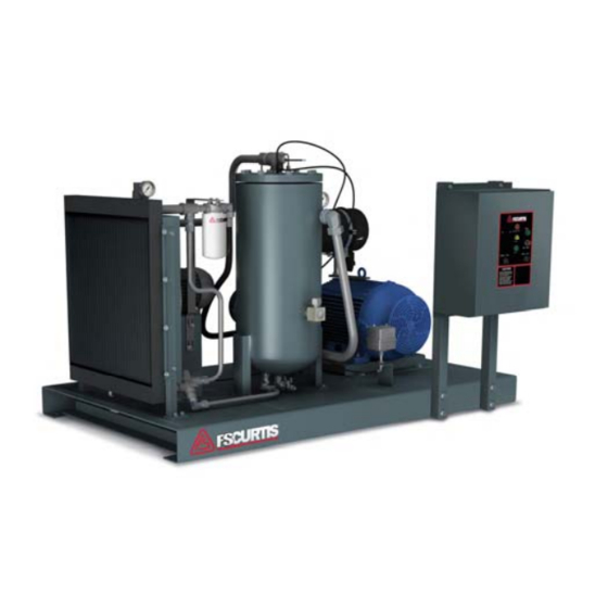
- Page 1 CAP303 REV Q SEPT 2020 Series OIL-INJECTED ROTARY SCREW COMPRESSORS OPERATOR MANUAL RSB-15 RSB-20 RSB-25 RSB-30 RSB-40 RSB-50...
-
Page 2: General Safety
CAP 303 SECTION 1 GENERAL SAFETY As with any piece of rotating equipment In addition to the obvious safety rules, we common sense and safety precautions recommend additional safety precautions as should be used in the operation of this rotary listed below. -
Page 3: Safety Decals
CAP 303 SAFETY DECALS Your compressor is posted with several safety where the hazard is most prevalent on the decals to inform the user of hazards associated compressor. Refer to the figures below for the with its operation. These decals are positioned decals used and their location on the compressor. - Page 4 CAP 303 Figure 1-2 Safety Decal Locations (Enclosed units)
-
Page 5: General Description
CAP 303 SECTION 2 GENERAL DESCRIPTION COMPRESSOR The compressor assembly is an oil flooded In operation as depicted below in the positive displacement, single stage, helical compression cycle (Ref. Figure 2-2), air screw type unit consisting of two rotors or entering the compressor through the inlet screws supported axially by roller bearings and port becomes trapped between the helical... -
Page 6: Air/Oil Flow
CAP 303 AIR/OIL FLOW Air enters the compressor through the air filter A sufficient amount of oil is stored in the oil and air inlet valve and into the air end where it is separator tank and is forced by the pressure of mixed with oil. -
Page 7: Installation
CAP 303 SECTION 3 INSTALLATION GENERAL LOCATION Upon receipt of your compressor, inspect for Your Curtis Rotary Screw compressor unit does freight damage. Report any damage as soon as not require a special foundation to operate. possible. See “FREIGHT DAMAGE PROCED- However, it is necessary that the floor be level URES”... -
Page 8: Inlet Air
CAP 303 INLET AIR WATER-COOLED UNITS A clean air supply is required for the satisfactory The cooling water supply should be checked to operation of your compressor. make sure the flow is sufficient. The chart shown in Figure 3-1 lists approximate minimum water flow rates in U.S. -
Page 9: Oil Level Check
CAP 303 OIL LEVEL CHECK Your compressor was shipped from the factory charged with the correct amount of compressor oil. However, the oil level must be checked at Electrical shock can cause severe injury installation and again prior to start-up. The or death. - Page 10 CAP 303 FREIGHT DAMAGE PROCEDURES 5. Call the factory and: 1. The customer or his agent MUST inspect Get a Return Material Authorization each shipment for damage at the receiving (RMA) number. point. Give a purchase order for repair. The 2.
-
Page 11: Operation
When the The RS Series compressors are equipped with system pressure does fall to the low setting the an automatic dual control operating system unit will restart turning off the standby light. -
Page 12: Minimum Pressure Valve
CAP 303 MINIMUM PRESSURE VALVE An internally loaded check valve that prevents the back flow of air from system pressure when the unit stops, unloads or is shut down. This valve also maintains approximately 65 PSI in the oil reservoir (Figure 4-2). Figure 4-2 Minimum Pressure Valve THERMOSTATIC CONTROL VALVE... -
Page 13: Initial Start-Up
CAP 303 INITIAL START-UP SHUTTING DOWN THE COMPRESSOR After completing the initial start-up checks, as Before shutting down the compressor, turn the noted in SECTION 3 “INSTALLATION”, the UNLOAD/LOAD switch to unload and allow the machine is ready to start. Turn the switch separator tank time to blow down i.e. - Page 14 Figure 4-4 Flow Diagram Load/Unload Control...
-
Page 15: Maintenance
CAP 303 SECTION 5 MAINTENANCE GENERAL Your Curtis Rotary Screw Compressor has been Standard air filter replacement (Figure 5-1) designed to require a minimum amount of maintenance. However, as with any piece of 1. Clean the exterior surfaces of the filter mechanical equipment, the implementation of a canister. - Page 16 Cap 303 2. Remove the filter cover. LUBRICANT 3. The heavy-duty filter consists of t wo elements, a main element wit h a safety Your compressor has been tested and shipped element inside. Remove the element then with a full charge of FS CURTIS LUBEPLUS the main element form the filter body.
- Page 17 CAP 303 6. Loosen the cap and make sure any additional 8. Refill with FS CURTIS LUBERPLUS FS C- pressure is relieved through the vent holes, 8000 Compressor lubricant. (Cons ult the then remove. specifications section for the proper amount 7.
-
Page 18: Separator Element
CAP 303 2. Allow one (1) minute after the compressor stops to allow the pressure to be relieved and FILTER HEAD the oil in the sump to settle.” (W/ BY-PASS) 3. Disconnect the main air line and the SET 25 PSI scavenger tube from the separator cover. - Page 19 CAP 303 SIGHT GLASS Thermostatic Control Valve Repair ORIFICE (Figure 5-6) 1. Place a spill pan under the valve. SCAVENGER TUBE 2. Remove the snap ring from the top of the valve body. The valve is spring loaded and the cap may pop up when COVER BOLT COVER the ring is removed.
-
Page 20: Drive System
CAP 303 Air exiting the vent hole in the cap indicates “O” DRIVE SYSTEM ring failure, allowing air to leak into the spring cavity inside the cap, which will effect the Routine examination of the drive system is operation of the valve. recommended to insure maximum compressor life. - Page 21 CAP 303 6. Replace with new belts. (Consult the appropriate parts list for your model to obtain the correct belt part number. Parallel misalignment occurs when the shafts are 7. Set tension by sliding the motor back to its original parallel but the face of the sheaves is not in alignment.
- Page 22 Replace as necessary or every 5 years. The maintenance intervals described herein are for normal operating condition in clean and well ventilated environments. Frequency of intervals will increase for non-standard environments. Please contact your authorized FSCURTIS distributor for more information and recommendations.
-
Page 23: Troubleshooting
CAP 303 TROUBLESHOOTING Symptom Probable Cause Remedy Power not turned on Turn power on by connecting main Failure to start disconnect switch or circuit breaker Blown main circuit fuse Replace fuse Blown control circuit fuse Replace fuse Safety circuit shutdown-high Correct situation per remedy described discharge temperature under “High Discharge Air Temperature”... - Page 24 CAP 303 TROUBLESHOOTING ( CON’T.) Symptom Probable Cause Remedy Not enough cooling water flowing Check water system possible High discharge air through the cooler (water cooled restriction, including water regulator temperature models) valve Inadequate circulation of cooling air at Check location of cooler to make sure cooler (air cooled models) there is no restriction to free circulation of cooling air.
- Page 25 CAP 303 TROUBLESHOOTING (CON’T.) Symptom Probable Cause Remedy Oil breakdown. Correct situation per remedy described in “Oil breakdown” section this troubleshooting guide Wrong oil being used Refer to SPECIFICATIONS section of this manual for correct oil Rapid start/stop or load/unload cycle Correct situation per remedy described in “Malfunctions in the capacity control system”...
- Page 26 CAP 303 TROUBLESHOOTING (CON’T.) Symptom Probable Cause Remedy Failure to drain condensate from the Drain condensate from the separator separator periodically. More frequent draining might be necessary when operating at high ambient temperature and high humidity environment. Mixing of different brands of oil DO NOT MIX DIFFERENT BRANDS OF Wrong type of oil being used Refer to SPECIFICATIONS section of this...
- Page 27 CAP 303 V-BELT TROUBLESHOOTING CHECK LIST Symptom Cause Remedy Compressor operating in highly Use remote air intake mounting Too frequent air filter contaminated area clogging Air filter not adequate for operating Use heavy duty air filter conditions Not enough tension Replace V-belt and apply proper tension Belts slip, shiny or glazed sheave sidewalls...
-
Page 28: Specifications
CAP 303 SECTION 6 SPECIFICATIONS ENGINEERING DATA MODEL RSB-15 RSB-20 RSB-25 RSB-30 RSB-40 RSB-50 V-BELT TYPE 5 (6) NUMBER OF BELTS OIL CAPACITY (GALLONS) 1 1/4 1 1/4 AIR IN CONNECTION OIL G.P.M. 1200 1550 2000 BTU/M - OIL COOLER BTU/M - AFTERCOOLER 3900 4800... - Page 29 CAP 303 2 1/4 57.15 DISCHARGE 1 1/4" NPT 8 1/2 215.9 914.4 914.4 914.4 FOR SERVICE FOR SERVICE FOR SERVICE 1117.357 38 1/16 966.788 965.2 1752.6 1066. 8 1828.8 9/16" 53 7/8 1368.273 Figure 6-2 Installation Drawing RSB 40 & 50 (Open Unit) 41 7/16 1524 1052.
- Page 30 CAP 303 914.4 FOR SERVICE 914.4 914.4 FOR SERVICE FOR SERVICE 2057.4 AIR DISCHARGE 1 1/2"NPT 1016 9/16" X 1 1/2" SLOTS 4 PLACES 42 1/2 1076.325 1346.2 TANK SIZE A B 200 GAL 42 80 RSB 40 240 GAL 54 92 200 GAL 42 ...
- Page 31 CAP 303 36 1/8 917.448 914.4 914.4 FOR SERVICE FOR SERVICE FOR SERVICE 1270 AIR DISCHARGE 1 1/4" NPT 38 1/16 1752.6 965.2 966.788 4 X 9/16" 1066.8 1828.8 53 1/4 1352.55 Figure 6-6 Installation Drawing RSB 40 & 50 (Enclosed Unit) 41 7/16 1052.512 1524...
- Page 32 CAP 303 71 3/4 1822.704 914.4 914.4 914.4 2209.8 FOR SERVICE FOR SERVICE FOR SERVICE 1878.012 AIR DISCHARGE 1 1/2" NPT 482.6 9/16" x 1 1/2" 1016 SLOTS 4 PLACES TANK SIZE A B 200 GAL 42 80 RSB 40 240 GAL 54 92 ...
- Page 33 CAP 303 Figure 6-10 Installation Drawing RSB 40 & 50 (Open Unit) Water Cooled Figure 6-11 Installation Drawing RSB 15 – 30 (Enclosed Unit) Water Cooled...
- Page 34 CAP 303 Figure 6-12 Installation Drawing RSB 40 & 50 (Enclosed Unit) Water Cooled...
- Page 35 CAP 303 WIRING DIAGRAM FOR FULL VOLTAGE START RSB MODELS...
- Page 36 CAP 303 WIRING DIAGRAM FOR WYE/DELTA START ...
- Page 37 CAP 303 WIRING DIAGRAM AND LOCATION DIAGRAM FOR WATERCOOLED RSB MODELS...
- Page 38 CAP 303 Recommended Bolt HHCS Torque Specifications HHCS Tightening Torque SAE 5 1/4-20UNC 10ft-lbs 5/16-18UNC 21 ft-lbs 3/8-16UNC 37 ft-lbs 1/2-13UNC 90 ft-lbs 5/8-11UNC 180 ft-lbs *Note: these values are for metal-to-metal joints when SAE 10 oil is used as lubricant. Separator Tank Lid Bolt Torque Specifications BOLT SEPARATOR...
-
Page 39: Heat Exchanger Tubes
CAP 303 COMPRESSOR MAINTENANCE LOG MODEL SERIAL NUMBER REFER TO THE COMPRESSOR INSTRUCTION MANUAL FOR COMPLETE MAINTENANCE INFORMATION AND SCHEDULE. THE COMPRESSOR INSTRUMENT PANEL LISTS A BRIEF MAINTENANCE OUTLINE DO NOT REMOVE LOG FROM THIS UNIT Record date in Date Column and hourmeter reading in the column under each item on which maintenance is performed. - Page 40 Curtis-Toledo, Inc. 1905 Kienlen Avenue | St. Louis, Missouri 63133 314-383-1300 or 800-925-5431 www.fscurtis.com | info@fscurtis.com...
Need help?
Do you have a question about the RS Series and is the answer not in the manual?
Questions and answers
WE HAVE THE RSB 15 COMPRESSOR WHAT IS THE CORRECT OIL FOR IT AND HOW MUCH DOES IT HOLD?