Sign In
Upload
Download
Table of Contents
Contents
Add to my manuals
Delete from my manuals
Share
URL of this page:
HTML Link:
Bookmark this page
Add
Manual will be automatically added to "My Manuals"
Print this page
×
Bookmark added
×
Added to my manuals
Manuals
Brands
FScurtis Manuals
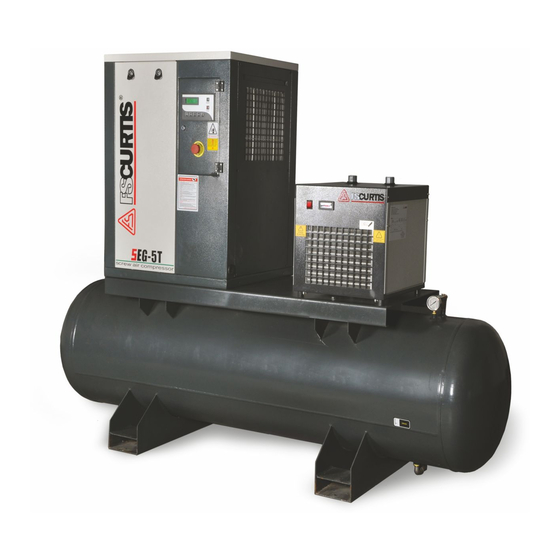
Air Compressor
SEG-5
Operator's manual
FScurtis SEG-5 Operator's Manual
Oil-injectedrotary screw compressors
Hide thumbs
1
Table Of Contents
2
3
4
5
6
7
8
9
10
11
12
13
14
15
16
17
18
19
20
21
22
23
24
25
26
27
28
29
30
31
32
33
34
35
36
37
38
39
40
41
42
43
44
page
of
44
Go
/
44
Contents
Table of Contents
Troubleshooting
Bookmarks
Table of Contents
Table of Contents
1 Introduction
Preface
Safety
2 Receiving and Installation
Installation / Precaution
Electrical
3 0 Principle of Screw Air Compressor
General
Air/Oil Flow
4 System Flow Chart and Components Function - System Flow Chart
Description
Protection / Warning
Control Systems / Electrical Circuit
Controller Operating Panel
5 0 Operation
Inspection
Storage
6 Maintenance
Maintenance Intervals
Air Filter / Oil Filter
Air/Oil Separator
Lubricant
Oil Analysis
Thermostatic & Minimum Pressure Valves
Belts
Sheave
Fan / Motor
Bearings
Air End/Motor Removal
7 Troubleshooting
8 Maintenance Log
Advertisement
Quick Links
1
Electrical
2
Maintenance Intervals
3
Air Filter / Oil Filter
4
Troubleshooting
5
Maintenance Log
Download this manual
SEG
OIL-INJECTED
OPERATOR
MANUAL
SEG-5
SEG-7.5 SEG-15
Series
ROTARY SCREW COMPRESSORS
SEG-10
CAP881
OCTOBER, 2012
REV.A
Table of
Contents
Previous
Page
Next
Page
1
2
3
4
5
Advertisement
Table of Contents
Need help?
Do you have a question about the SEG-5 and is the answer not in the manual?
Ask a question
Questions and answers
Related Manuals for FScurtis SEG-5
Air Compressor FScurtis SEG-15 Operator's Manual
Oil-injectedrotary screw compressors (44 pages)
Air Compressor FScurtis SEG-10 Operator's Manual
Oil-injectedrotary screw compressors (44 pages)
Air Compressor FScurtis SE Series Operator's Manual
Belt driven rotary screw compressors (42 pages)
Air Compressor FScurtis SE25 Operator's Manual
Belt driven rotary screw compressors (42 pages)
Air Compressor FScurtis SE30 Operator's Manual
Belt driven rotary screw compressors (42 pages)
Air Compressor FScurtis ECO Scroll Series Instruction Manual
Oil free compressors (40 pages)
Air Compressor FScurtis CA series Installation And Operating Instruction Manual
Air compressor (49 pages)
Air Compressor FScurtis RS Series Operator's Manual
Oil-injectedrotary screw compressors (41 pages)
Air Compressor FScurtis CA Series Installation And Operation Manual
Two stage reciprocating air compressors (32 pages)
Air Compressor FScurtis Nx Series Operator's Manual
Icommand - touch controller (60 pages)
Air Compressor FScurtis NxB/V Series Operator's Manual
Oil-injected rotary screw compressors (60 pages)
Air Compressor FScurtis ECO Series Operator's Manual
Oil – free scroll compressor (54 pages)
Air Compressor FScurtis FCT05C30V6X-A2X1XX Operating Instructions And Parts Manual
Single stage (23 pages)
Air Compressor FScurtis FCT02C48H2X-A1X1XX Operating Instructions And Parts Manual
20 gallon portable (23 pages)
Air Compressor FScurtis FCT02C48V3X-A1X1XX Operating Instructions And Parts Manual
Portable air compressor (69 pages)
Air Compressor FScurtis ECO ES04 Manual
Oil-free scroll compressor (20 pages)
This manual is also suitable for:
Seg-7.5
Seg-15
Seg-10
Table of Contents
Print
Rename the bookmark
Delete bookmark?
Delete from my manuals?
Login
Sign In
OR
Sign in with Facebook
Sign in with Google
Upload manual
Upload from disk
Upload from URL


Need help?
Do you have a question about the SEG-5 and is the answer not in the manual?
Questions and answers