
Subscribe to Our Youtube Channel
Related Manuals for ASROCK Rack 1U4LW Series


Summary of Contents for ASROCK Rack 1U4LW Series
- Page 1 1U4LW Series 1U4L Series User Manual Version 1.0 Published December 2022 Copyright©2022 ASRock Rack INC. All rights reserved.
- Page 2 In no event shall ASRock Rack, its directors, officers, employees, or agents be liable for any indirect, special, incidental, or consequential damages (including damages for loss of profits, loss of business, loss of data, interruption of business and the like), even if ASRock Rack has been advised of the possibility of such damages arising from any defect or error in the documentation or product.
- Page 3 Setting up the Server in a Restricted Access Location • Access can only be gained by service persons or by users who have been instructed about the reasons for the restrictions applied to the location and about any precautions that shall be taken. •...
-
Page 4: Table Of Contents
Contents Chapter 1 Introduction Shipping Box Contents Specifications Chapter 2 Server System Overview System Components Internal Features System Front Panel System Rear Panel Front Control Panel Buttons and LEDs Drive Tray LEDs Chapter 3 Hardware Installation and Maintenance Server Top Cover Hard Drive Power Supply System Fan... -
Page 6: Chapter 1 Introduction
1U4LW Series Chapter 1 Introduction Thank you for purchasing 1U4LW Series, a reliable barebone system produced under ASRock Rack’s consistently stringent quality control. It delivers excellent performance with robust design conforming to ASRock Rack’s commitment to quality and endurance. This guide provides the instructions of insertion and extraction of chassis components, such as chassis covers, system fans, power supplies, hard disk drive trays, and other main components this system supports. -
Page 7: Shipping Box Contents
1.1 Shipping Box Contents Item Quantity 1U4LW- C224/C232 X470 Series X570 Series 1U4LW Series 1U Barebone System Board (MB) Power Supply Unit 1 (RPSU: 2) 1 (RPSU: 2) System Fan HDD Backplane (BPB) Front Panel Board (FPB) Accessory Box 1U Cooler/Heatsink... -
Page 8: Specifications
4 x 3.5'' SATA HDD (6Gb/s) Internal 1U4LW-C252: 2 x 2.5" SATA HDD (or 1 x 2.5" SATA HDD + 1 x SATA-type Slim ODD (optional)) Other 1U4LW Series Models: 3 x 2.5" SATA HDD 1U4LW-B650/2L2T: System Cooling 1U4LW-ICX/2T: 4 x 40 x 28 mm PWM Easy-Swap Fans... -
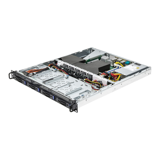
Page 9: Chapter 2 Server System Overview
Chapter 2 Server System Overview This chapter provides diagrams showing the location of important components of the server system. 2.1 System Components SPSU Series: Top Cover 1 x Power Supply Unit RPSU Series: 2 x Power Supply Units System Fans Server Board 1 x 2.5”... -
Page 10: Internal Features
1U4LW Series 2.2 Internal Features From Riser Card Serverboard 1U4LW SPSU Series: 1 x Power Supply Unit (PSU) 1U4LW RPSU Series: 2 x Power Supply Units (PSU) System Fan 5 (1U4LW-ICX/2T not supported) System Fan 4 System Fan 3 System Fan 2... -
Page 11: System Front Panel
2.3 System Front Panel Description Control Panel Buttons and LEDs 2 x USB 3.2 Gen1 Ports 4 x 3.5" Hot-Swap HDD Trays 1 x Slim ODD Carrier (Optional) (for 1U4LW-C252 only) 2.4 System Rear Panel 1U4LW SPSU Series 1U4LW RPSU Series Description 1U4LW-SPSU: 1 x Power Supply Unit (PSU) 1U4LW-RPSU: 2 x Power Supply Units (PSU) -
Page 12: Front Control Panel Buttons And Leds
1U4LW Series 2.5 Front Control Panel Buttons and LEDs Front Control Panel (1U4LW-X470 / 1U4LW-C252 / 1U4LW-ICX/2T / 1U4LW-ROME/2T Series) Description ID Button and LED Power Button and LED NMI (Nonmaskable Interrupt) Button System Reset Button LAN1, LAN2, LAN3, LAN4 Activity LED LAN1 and LAN2 are only supported on the 1U4LW-ICX/2T / 1U4LW-ROME/2T systems. - Page 13 NMI (Nonmaskable Interrupt) Button Press the NMI button with a paper clip or pin to generate a nonmaskable interrupt and to put the server in a halt state for examination. System Reset Button When the system is completely unresponsive, press the system reset button to reboot the server without shutting it off and initialize the system.
-
Page 14: Drive Tray Leds
1U4LW Series LAN LED Status Description Blinking Green Network access Solid Green LAN is present. No LAN is present. 2.6 Drive Tray LEDs Description HDD Power LED HDD Activity LED Status LED Definitions HDD Power LED Status Description Blue HDD powered-on... -
Page 15: Chapter 3 Hardware Installation And Maintenance
Chapter 3 Hardware Installation and Maintenance This chapter helps you assemble the chassis and install components. Before You Begin Before you work with the server, pay close attention to the “Important Safety Instructions” at the beginning of this manual. 1. Make sure the server is powered off. Power down the server if it is still running. -
Page 16: Server Top Cover
1U4LW Series 3.1 Server Top Cover Removing the Server Top Cover 1. Before removing the top cover, power off the server and unplug the power cord. 2. The system must be operated with the chassis top cover installed to ensure proper cooling. - Page 17 Installing the Server Top Cover 1. Lower the top cover on the chassis, making sure the side latches align with the cutouts. 2. Slide the top cover toward the front. 3. Secure the top cover with the screws.
-
Page 18: Hard Drive
1U4LW Series 3.2 Hard Drive Removing 3.5” Hard Drive Trays from the Chassis 1. Press the locking lever latch on the drive tray to unlock the retention lever. 2. Rotate the lever out and away from the module bay and pull the hard drive out of the... - Page 19 Installing a 3.5” Hard Drive to the Hard Drive Tray 1. Place the 3.5" HDD into the tray with the printed circuit board side facing down. Carefully align the mounting holes in the hard drive and the tray. 2. Secure the hard drive using the four screws. 3.
- Page 20 1U4LW Series Removing a 2.5” Hard Drive Carrier from the Chassis 1. Hand-release the thumbscrew that secures the hard drive carrier to the chassis. 2. Push the carrier toward the rear of the chassis to remove it from the locked position.
- Page 21 Installing a 2.5” Hard Drive to the Hard Drive Carrier 1. Place a 2.5" HDD into the carrier with the printed circuit board side facing down. 2. Secure the hard drive to the carrier with screws. 3. Put the hard drive assembly back into the chassis and slide it toward the front. 4.
-
Page 22: Power Supply
1U4LW Series 3.3 Power Supply Installing and Removing the Power Supply Before replacing the power supply, power off the server, unplug the power cord, and discon- nect all wiring from the power supply. The 1U4LW SPSU Series system supports single PSU only. - Page 23 Removing the Power Supply Unit To remove a failed power supply, identify the failed power supply by checking the power supply LEDs on the PSU. 1. Hold onto the power supply handle while pressing the locking lever towards the power supply handle.* *The illustration is for references only.
-
Page 24: System Fan
1U4LW Series 3.4 System Fan Replacing the Simple-Swap Fan 1. Press and hold the clip on the fan. 2. Press and hold the clip on the middle fan. -
Page 25: Add-On Card
3.5 Add-on Card 1. You can install an add-on card to the chassis only when you have a riser card installed on the server board. 2. Before installing the add-on card, power off the server and unplug the power cord. Removing the Riser-Card Bracket from the Chassis 1. - Page 26 1U4LW Series Installing the Add-on Card 1. Install the add-on card to the riser-card bracket. 2. Secure the add-on card to the bracket with a screw . 3. Align the riser-card assembly with the openings of the chassis. 4. Hand-tighten the thumbscrew to secure the assembly to the chassis.
-
Page 27: Air Duct
3.6 Air Duct 1. If an add-on card is already installed, remove the add-on card assembly from the chassis before installing the air duct. If an add-on card is not installed yet, install the add-on card first. Please see the chapter entitled "Add-on Card" for more instructions. 2. - Page 28 1U4LW Series 3. Then install the add-on card assembly to the chassis. For 1U4LW-X470 Series only: Air Duct (add-on card) Riser Card Assembly 4. 1U4LW-X470 Series only: Make sure the add-on card assembly is well aligned with the air duct.
- Page 29 5. Align the air duct over the heat sink and carefully lower the air duct in place. Please note the illustrations of the air ducts here are examples only. The looks may be different by products. 1U4LW-X470 Series 1U4LW-X570 Series...
- Page 30 1U4LW Series 1U4LW-C252 Series 1U4LW-ICX/2T Series...
- Page 31 1U4LW-ROME/2T Series 1U4LW-B650/2L2T...
-
Page 32: Installing The Cpu
1U4LW Series Appendix A Installing the CPU (AMD AM4 Socket) - Page 34 1U4LW Series...
- Page 35 Please be aware of the correct direction when you install the CPU heatsink. Make sure the the arrow on the CPU heatsink is pointing to the opposite side of the system fan. Air Flow Direction...
- Page 36 1U4LW Series Installing the CPU (LGA 1200 Socket) 1. Before you insert the 1151-Pin CPU into the socket, please check if the PnP cap is on the socket, if the CPU surface is unclean, or if there are any bent pins in the socket. Do not force to insert the CPU into the socket if above situation is found.
- Page 37 Please save and replace the cover if the processor is removed. The cover must be placed if you wish to return the motherboard for after service.
- Page 38 1U4LW Series...
- Page 39 Installing the CPU (LGA 4189 Socket) 1. Before you insert the CPU into the socket, please check if the PnP cap is on the socket, if the CPU surface is unclean, or if there are any bent pins in the socket. Do not force to insert the CPU into the socket if above situation is found.
- Page 40 1U4LW Series 1. Before you installed the heatsink, you need to spray thermal interface material between the CPU and the heatsink to improve heat dissipation. 2. Illustration in this documentation are examples only. Heatsink or fan cooler type may differ.
- Page 42 1U4LW Series CPU Carrier...
- Page 43 Heatsink CPU Carrier Socket...
- Page 44 1U4LW Series Illustrations in this User Manual are provided for reference only and may slightly differ from actual product appearances.
- Page 45 Installing the CPU (LGA 4094 Socket) 1. Before you insert the CPU into the socket, please check if the PnP cap is on the socket, if the CPU surface is unclean, or if there are any bent pins in the socket. Do not force to insert the CPU into the socket if above situation is found.
- Page 46 1U4LW Series...
- Page 47 Carr ier Frame with CPU Rail Frame Please make sure that the carrier frame with CPU is closely attached to the rail frame while inserting it. Install the carrier frame with CPU. Don’t separate them.
- Page 48 1U4LW Series...
- Page 49 Installing the CPU (LGA 1718 Socket) 1. Before you insert the 1718-Pin CPU into the socket, please check if the PnP cap is on the socket, if the CPU surface is unclean, or if there are any bent pins in the socket. Do not force to insert the CPU into the socket if above situation is found.
- Page 50 1U4LW Series Carefully place the CPU in as flat as possible. Do not drop it.
- Page 51 Make sure the CPU is aligned with the socket before locking it into place. Make sure the black cover plate is always in place until it pops off when closing the socket lever. Please save the cover if the processor is removed. The cover must be placed if you wish to return the motherboard for after service.
- Page 52 1U4LW Series Installing the CPU Fan and Heatsink After you install the CPU into this motherboard, it is necessary to install a larger heatsink and cooling fan to dissipate heat. You also need to spray thermal grease between the CPU and the heatsink to improve heat dissipation. Make sure that the CPU and the heatsink are securely fastened and in good contact with each other.
-
Page 54: Installation Of Memory Modules (Dimm)
1U4LW Series Appendix B Installation of Memory Modules (DIMM) The DIMM only fits in one correct orientation. It will cause permanent damage to the motherboard and the DIMM if you force the DIMM into the slot at incorrect orientation. For more information about DIMM installation, please refer to the User Manual that comes with the serverboard you use. - Page 55 Type B (Two Clips)
-
Page 56: Block Diagram
1U4LW Series Appendix C Block Diagram (E3C252D4U) Tatlow Platform P P C C I I - - E E G G e e n n 4 4 X X 1 1 6 6 D D D D R R 4 4 2 2 6 6 6 6 6 6 / / 2 2 9 9 3 3 3 3 / / 3 3 2 2 0 0 0 0 ( ( E E C C C C / / n n o o n n - - E E C C C C ) ) - Page 57 Block Diagram (SPC621D8U-2T) DMI3 x4...
- Page 58 1U4LW Series Block Diagram (ROMED8U-2T) MAC2 Ethernet 1.1 & PCI-Express 10/100/1000 PCIE Gen3 x 1 DDR4 DDR4 DDR4 DDR4 USB2.0 x 2 PCI-E DDR4 DDR4 DDR4 DDR4...
- Page 59 Block Diagram (X470D4U)
- Page 60 1U4LW Series Block Diagram (E3C242D4U) E3C242D4U P P C C I I - - E E G G e e n n 3 3 B B U U S S 1 1 0 0 0 0 M M H H z z...
- Page 61 Block Diagram (B650D4U-2L2T)
Need help?
Do you have a question about the 1U4LW Series and is the answer not in the manual?
Questions and answers