Table of Contents
Advertisement
Quick Links
About this Practice:
This practice has been reissued to:
• Update Technical Specifications
table.
Reissued Practices: Updated and
new content can be identified by a
banner in the right margin.
Issue date: July 1998
Copyright 1998 by Dantel, Inc. • Dantel is a registered trademark of Dantel, Inc. • ISO 9001 Registered
44210 460 M
49210 T
I
NTERFACE
Table of Contents
Ordering Information ........................................................................... 2
General Description .............................................................................. 2
Circuit Description ............................................................................... 2
Application Information ....................................................................... 7
Installation .......................................................................................... 10
Operation ............................................................................................ 16
FCC Required Information ................................................................ 20
Technical Specifications ..................................................................... 21
Warranty ............................................................................................. 22
CAUTION
•
Install or remove modules from the shelf only when the power is off.
If you install a module in the shelf with the power on, the internal
circuitry may suffer damage and the product warranty will be void.
•
Remove and install circuit boards only in a static-safe environment
(use antistatic wrist straps, smocks, footwear, etc.).
•
Keep circuit boards in their antistatic bags when they are not in use.
•
Do not ship or store circuit boards near strong electrostatic, electromag-
netic, magnetic, or radioactive fields.
•
For more complete information on electrostatic discharge safety
precautions, refer to Bellcore
Printed in the U.S.A.
I
& O
NSTALLATION
44210/49210-0798 <90-00025>
ODEM
-L
WO
INE
S
UBASSEMBLY
44210-00
460 Modem
L
I
N
TD
E
M
DTR
O
N
OFF
RD
HOOK
CD
RING
ESD
RESET
49210-00
LINE
1
LINE
2
TWO LINE
INTERFACE
44210-00 REV__
TM
Technical Reference # TR-NWT-000870.
M
PERATION
ANUAL
&
Advertisement
Table of Contents

Related Manuals for Dantel 44210


Summary of Contents for Dantel 44210
-
Page 1: Table Of Contents
For more complete information on electrostatic discharge safety Issue date: July 1998 precautions, refer to Bellcore Technical Reference # TR-NWT-000870. Copyright 1998 by Dantel, Inc. • Dantel is a registered trademark of Dantel, Inc. • ISO 9001 Registered Printed in the U.S.A. -
Page 2: Ordering Information
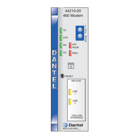
The optional 49210 subassembly provides an interface to two telephone lines; a primary and a backup. The 44210 is a plug-in module that fits into any 400-type or similiar equipment housing. The front panel has status-indicat- ing LEDs, normal-through and monitoring jacks, test points, level-setting potentiometers, and a subassembly cutout window. - Page 3 CIRCUIT DESCRIPTION . 1 - F , 44210/49210 UNCTIONAL CHEMATIC 44210/49210-0798 <90-00025>...
- Page 4 The microprocessor provides central processing power to coordi- nate virtually all on-board functions carried out by the 44210. When power is initially applied to the 44210, a watchdog IC resets the microprocessor and UART. The microprocessor must pulse the watch dog IC within 1.2 seconds, or the watchdog IC resets the microprocessor again.
- Page 5 MPI Inputs Six MPI inputs directly interface the microprocessor on the 44210 using edge connector pins. When an MPI input becomes active, the microprocessor's input goes to a low state, causing the microprocessor to perform a dial-out. One of the MPI inputs (pin 22) is TTL/CMOS-compatible and is activated by grounding (ground to 1.5 VDC) and inactive when left open (3.0 to 5.0...
- Page 6 2 is grounded (with input 1 open or high), the relay is ON and line 2 is connected to the 44210 modem. If both line- select inputs are open or at a high level, the relay remains in the state appropriate to the last selected line.
-
Page 7: Application Information
LEDs. Override Switch The switch overrides the relay and line selectors, connecting only the selected line to the 44210 modem. If the override switch is in the center (OFF) position, then line selection is done by the line selectors. APPLICATION INFORMATION... - Page 8 FUNCTION DB-9 PINS DB-25 PINS Auto-Answer Refer to Fig. 2. When a 44210 is configured in this mode, it acts as an auto-answer modem (not Hayes -compatible). It answers an incoming call and establishes communications only. There is no automatic call-out on alarm or password features. When it hangs up, it will send a garbage character to the device to which it is connected.
- Page 9 APPLICATION INFORMATION modem, it must hang up itself after sending "+++". This mode is usually used when a 44210 is tied to a MAP's or 46062 General Purpose Processor's (GPP) Printer Port. Option Strapping and Switch Settings The 44210 has straps to configure the RS-422 and RS-485 ports and the operation of RTS and DTR.
-
Page 10: Installation
J5 of the 44210. Four screws must be removed prior to mounting the 49210 on connectors J4, J5, and J6. Refer to Fig. 4. After mounting the 49210 on the 44210 module, replace the same four screws to hold the subassembly securely in place. - Page 11 If the 44210 is used in Hayes-compatible mode, refer to Table B or the instruction manual of the communications software in use. Checkout of the 44210 is done by placing the 44210 in operation with one or more 44210s or similiar modems at the distant end that are known to be good.
- Page 12 POSITION DESCRIPTION Only line 1 connected to 44210 modem Only line 2 connected to 44210 modem Whichever line receives ringing voltage is connected to 44210 modem. NOTE: Refer to the Application Information section for a complete discussion of operating modes.
- Page 13 INSTALLATION . 4 - S , 44210/49210 WITCH AND TRAP OCATIONS ON EXT 49210 SUBASSEMBLY TERM 1 OFF 2 422DTR 422TXD 485TXD 1 2 3 4 5 6 7 8 BOTTOM VIEW OF MODULE . 5 - S , 460 ACS M...
- Page 14 5 6 7 8 BOTTOM VIEW OF MODULE . 8 - S , 460 ACS A WITCH ETTINGS NSWER SWITCH S1-1 THROUGH S1-8 POSITIONS AS SHOWN 1 2 3 4 5 6 7 8 BOTTOM VIEW OF MODULE 44210/49210-0798 <90-00025>...
- Page 15 INSTALLATION . 9 - P , 44210 M ESIGNATIONS ODEM Audio Monitor Line Select #2 Line Select #1 2-Wire Line #1 2-Wire Line #1 Off Hook Ring Detect #2 Ring Detect #1 -21 to -56 VDC RTS (TTL) DTR (TTL)
-
Page 16: Operation
Dantel's 460 Alarm and Control System (460 ACS), refer to Fig. 10 and the Application section of this manual. For information on using the 44210 as a Hayes -compatible modem, or dumb 202 modem, refer to Table B, and the documentation specific to the communication software being used. - Page 17 Result from X2 or X4 command only. BUSY Busy signal detected and subsequent commands not processed. Result from X3 or X4 command only. NO ANSWER Silence not detected and subsequent commands not processed. Result from @ command only..CONTINUED 44210/49210-0798 <90-00025>...
- Page 18 49210 Two- 460 Modem Line Interface Subassembly. When no subassembly is mounted on the 44210, a bypass card is mounted in place of the subas- sembly and a plastic insert fills the cutout opening. Refer to Fig. 10 and Table C.
- Page 19 Comes ON, and stays ON, as long as line 2 of the 49210 subassembly is active. NOTE: If an LED is flashing (approximately 2 seconds ON and 4 seconds OFF) it indicates detection of interrupted ringing voltage and that the line is NOT connected to the modem. 44210/49210-0798 <90-00025>...
-
Page 20: Fcc Required Information
Installation of this equipment as an adjunct can be made only with permission of the owner of the host equipment. FCC required information pertaining to this module: Registration Number: DPH622-60575-MD-E 44210/49210-0798 <90-00025>... -
Page 21: Technical Specifications
DESCRIPTION VALUE POWER REQUIREMENTS Input Voltage -21 to -56 VDC Input Current (+5%; add 18mA when 44210 is e/w 152mA max. @ -21 VDC 49210) 140mA max. @ -24 VDC 97mA max. @ -48 VDC 91mA max. @ -56 VDC Heat Dissipation (add 0.4 Btu when 44210 is e/w... -
Page 22: Warranty
To ensure expedient processing of your order, provide a purchase order number and shipping and billing information when requesting an RMA number. Also, when the units are returned to Dantel, include a descrip- tion of the failure symptoms for each unit returned. Send defective equipment to: Dantel, Inc.
Need help?
Do you have a question about the 44210 and is the answer not in the manual?
Questions and answers