Advertisement
Quick Links
About this Practice:
This practice has been reissued to:
• Update Figs. 2, 4-6, 16, & 20.
Reissued Practices: Updated and
new content can be identified by a
banner in the right margin.
Issue date: July 1998
Copyright 1998 by Dantel, Inc. • Dantel is a registered trademark of Dantel, Inc. • ISO 9001 Registered
D18-05547-XX
DTSS3A O
W
I
NTERFACE
Table of Contents
Ordering Information ........................................................................... 2
General Description .............................................................................. 2
Application Information ....................................................................... 3
Installation ............................................................................................ 5
Operation ............................................................................................ 23
Warranty ............................................................................................. 26
CAUTION
•
Install or remove modules from the shelf only when the power is off.
If you install a module in the shelf with the power on, the internal
circuitry may suffer damage and the product warranty will be void.
•
Remove and install circuit boards only in a static-safe environment
(use antistatic wrist straps, smocks, footwear, etc.).
•
Keep circuit boards in their antistatic bags when they are not in use.
•
Do not ship or store circuit boards near strong electrostatic, electromag-
netic, magnetic, or radioactive fields.
•
For more complete information on electrostatic discharge safety
precautions, refer to Bellcore
Printed in the U.S.A.
I
NSTALLATION
/D
IRE
ATA
Technical Reference # TR-NWT-000870.
TM
& O
M
PERATION
ANUAL
05547-0798 <90-00047>
RDER
Advertisement

Related Manuals for Dantel D18-05547 Series


Summary of Contents for Dantel D18-05547 Series
-
Page 1: Table Of Contents
For more complete information on electrostatic discharge safety precautions, refer to Bellcore Technical Reference # TR-NWT-000870. Issue date: July 1998 Copyright 1998 by Dantel, Inc. • Dantel is a registered trademark of Dantel, Inc. • ISO 9001 Registered Printed in the U.S.A. -
Page 2: Ordering Information
ORDERING INFORMATION NOTE: This section lists the different options available for this product. To order any of the avail- able options, contact Dantel Inside Sales through our toll-free number, 1-800-432-6835. OPTION NUMBER FEATURES D18-05547-01 Wired assembly with 41096 Order-Wire Panel, one DTSS3A, 3-digit dialing, one 46105 64Kb... -
Page 3: Application Information
APPLICATION INFORMATION efer to Fig. 1 for an application drawing of the system. . 1 - 05547 A PPLICATION DTSS3ON Order Wire Network Internet Shelf Off-Net Assembly Public Switched Telephone 00331-00 05723-01 Network MASTER (CALLED) TERMINAL REMOTE (CALLED) TERMINAL 05547-xx 05547-xx FIBER FIBER... - Page 4 APPLICATION INFORMATION PPLICATION When you use the order wire system as a voice circuit, you dial a preset number (station 1 code) to call someone at a remote terminal. When you use the system as a data circuit, you dial a different number (station 2 code) to call the same remote termi- nal to set up a data communications path.
-
Page 5: Installation
INSTALLATION his chapter consists of five sections which install and set up the 05547-01. These sections are: Equipment Mounting, Wiring, Switch and Strap Settings, Turn-Up Procedure, and Troubleshooting. Follow these sections in order. Following those are sections on the 00331 Off-Net Interface and the 05723 Network Interface Shelf. - Page 6 INSTALLATION . 2 - TB1 L OCATION (TB1) FUSE -BATT CAUTION: Do not reverse power C5 U3 C6 U5 1 1 1 PORT 4 TERMINATION PORT 2 PHONE TERMINATION P2 1 JACK IN OUT IN OUT IN OUT SYSTEM REAR VIEW .
- Page 7 INSTALLATION IRING To wire the equipment assembly: Wire the 46105 Dual VF 64-Kilobit Channel module to the fiber optic terminal. Refer to the D18-05547-XX Block Diagram. Channel 1 is labeled J6. Channel 2 is labeled J5. J1 can be used instead of J5 and Do all wiring at the rear J6 if wire-wrap connections are preferred.
- Page 8 INSTALLATION WITCH AND TRAP ETTINGS 33337-00 E QUIPMENT HELF To set the straps: Refer to Fig. 5 for the location of the straps. All switch, strap, and level set- tings are factory-set. ♦ Set JP1 in the 1-2 position if the battery is -48 VDC. ♦...
- Page 9 INSTALLATION 00330-02 O RDER ERMINAL HELF All switch, strap, and level set- To set the switches: tings are factory-set. Remove the back panel cover plate to verify that the switches are set according to Fig. 6. . 6 - 00330-02 O RDER WITCH OCATIONS...
- Page 10 INSTALLATION . 7 - 41096 P ANEL TRAP OCATIONS 46105 D VF 64-K ILOBIT HANNEL ODULE To set the switches: All switch, strap, and level settings are factory-set. Refer to Fig. 8 for the locations of the switches. Set S1 (BRDG) in RPTR. Set S2 (LPBK 1) in OFF.
- Page 11 INSTALLATION . 8 - 46105 S WITCH AND TRAP OCATIONS CHANNEL 1 BRDG TERM RPTR LPBK 1 M LEAD 2 NO YES E LEAD TERM MODE RPTR DATA DATA CHANNEL S101 LPBK 2 05547-0798 <90-00047>...
- Page 12 INSTALLATION 44214 9600 BPS M ODEM The 44214 communicates with a second 44214 at the other end. One of these two To set the switches and straps: modules must have its ORG/ Refer to Fig. 9 for the locations of the switches and straps. ANS switch set for ORG and the other module must be On the front panel of the module, set the ALB and DLB switches (S3...
- Page 13 INSTALLATION 44020 DTMF D 49018 S ECODER WITH TATION ELECTOR UBASSEMBLY To set the switches and straps: Verify that the switches and straps are set according to Figs. 10 and On the 49018 subassembly, set the station 1 code with S1, S2, and S3.
- Page 14 INSTALLATION . 11 - 49018 S WITCH AND TRAP OCATIONS 49018-00 1 DIGIT CKT 1 CLR (X5) 2 DIGIT CKT 1 3 DIGIT CKT 2 CKT 2 RESET SET(X4) OPTIONAL SETTING STATION SELECTOR 44022 S TATION NTERFACE ODULE To set the straps: Verify that the straps are set according to Fig.
- Page 15 INSTALLATION 49920 I NTERRUPT UPPLY ODULE To set the switches and straps: Verify that the switches and straps are set according to Fig. 13. Reinstall the module in the right slot of the bottom equipment shelf. . 13 - 49920 S WITCH AND TRAP OCATIONS...
- Page 16 INSTALLATION Check the system. The order wire system is aligned at the factory. Once installed, it is ready to operate. Follow the procedures in the Operation chapter to check the system as a voice circuit and as a data circuit. Adjusting Signal Levels Follow the procedures below if you have to check signal levels or, if you install replacement equipment, to set the levels.
- Page 17 INSTALLATION Proceed to the next section to align the 44214 modem, or apply power to the system and follow the procedures in the Operation chapter to check the system. 44214 M ODEM LIGNMENT Set modem to Originate Mode Set Switch 4, accessible through the front panel, to ORG. Adjust transmit level Connect a 600 ohm terminated dB meter to the module.
- Page 18 INSTALLATION Verify that the switches and straps are set as shown in Figs. 15-18 and Table A. Wiring Connect the 00331 Off-Net Interface to the 05547 Assembly. Refer to page 3 of 6 of the D18-05547-XX Block Diagram. . 15 - 44020 DTMF D ECODER TRAP ETTINGS...
- Page 19 INSTALLATION . 17 - 44023 PABX/T RUNK NTERFACE TRAP ETTINGS 44023-00 PABX/TRUNK XMT PAD INTERFACE BUSY LED BUSY CONT INC CALL INC CALL LED OFF HOOK OFF HOOK LED START TRANSMIT LINE XMT LEVEL ADJUST DIST M LEAD BATTERY DROP TEST PRIVACY IN OUT...
- Page 20 INSTALLATION . 18 - 44443 F WITCH AND TRAP ETTINGS 44443-XX TERM SET RCV ATTEN (dB) OUT IN OUT IN AB CAP 4 WIRE LINE B INT BYPASS A INT BYPASS 2 WIRE DROP XMT ATTEN (dB) OUT IN OUT IN OPEN A11-44443-00 05547-0798 <90-00047>...
- Page 21 INSTALLATION A - 00331 O ABLE WITCH AND TRAP ETTINGS BACKPLANE Called Party S1 DOWN Line T/R Normal S2 NOR UP Line T/R Reversed S2 REV DOWN * Control S3 * DOWN # Control S3 # UP 44020 MODULE Input Impedance BRDG Input Level 0 to -20dBm Dial Tone Filter In...
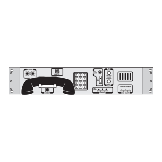
- Page 22 INSTALLATION A18-05723-01 N WITCH AND TRAP ETTINGS FOR ETWORK NTERFACE HELF This shelf is part of the D18-05547-04. Fig. 19 shows the front view of this shelf. . 19 - 05723 F RONT Switch and Strap Settings Verify that the switches and straps are set as shown in Fig. 20. .
-
Page 23: Operation
OPERATION he 05547 Order Wire system can be used for either voice or data communications. OICE IRCUIT The system operates as a standard order wire when you use it for voice communications. You can call one or more remote terminals. To monitor the order wire system: Only channel 1 is connected to the speaker. - Page 24 OPERATION Pick up the handset and dial the three-digit station 2 code of the re- mote terminal. Hold in the CHANNEL 1 button and push in the CHANNEL 2 but- ton. (Both buttons are pushed in.) Hang up the handset. Start transmitting or receiving data.
- Page 25 OPERATION Typically, dial tone detection is disabled with the following com- mand: ATX3. This command, however, combines several other commands with it, such as external results codes and busy tone detection. Other commands which would disable dial tone detection are: ATX0 or ATX1 Dial the Off-Net shelf.
-
Page 26: Warranty
To ensure expedient processing of your order, provide a purchase order number and shipping and billing information when requesting an RMA number. Also, when the units are returned to Dantel, include a descrip- tion of the failure symptoms for each unit returned. Send defective equipment to: Dantel, Inc.
Need help?
Do you have a question about the D18-05547 Series and is the answer not in the manual?
Questions and answers