Advertisement
Quick Links
About this Practice:
• This document has been
reformated to meet ISO 9001
requirements.
Reissued Practices: Updated and
new content can be identified by a
banner in the right margin.
Issue date: June 1997
Copyright 1997 by Dantel, Inc. • Dantel is a registered trademark of Dantel, Inc. • ISO 9001 Registered
49018 S
S
S
UBASSEMBLY
Table of Contents
Ordering Information ........................................................................... 2
General Description .............................................................................. 2
Circuit Description ............................................................................... 3
Application Information ....................................................................... 7
Installation ............................................................................................ 9
Operation ............................................................................................ 11
Technical Specifications ..................................................................... 12
Warranty ............................................................................................. 14
CAUTION
•
Install or remove modules from the shelf only when the power is off.
If you install a module in the shelf with the power on, the internal
circuitry may suffer damage and the product warranty will be void.
•
Remove and install circuit boards only in a static-safe environment
(use antistatic wrist straps, smocks, footwear, etc.).
•
Keep circuit boards in their antistatic bags when they are not in use.
•
Do not ship or store circuit boards near strong electrostatic, electromag-
netic, magnetic, or radioactive fields.
•
For more complete information on electrostatic discharge safety
precautions, refer to Bellcore
Printed in the U.S.A.
I
NSTALLATION
TATION
ELECTOR
Technical Reference # TR-NWT-000870.
TM
& O
M
PERATION
ANUAL
49018-0697 <90-00089>
Advertisement

Related Manuals for Dantel 49018


Summary of Contents for Dantel 49018
-
Page 1: Table Of Contents
For more complete information on electrostatic discharge safety precautions, refer to Bellcore Technical Reference # TR-NWT-000870. Issue date: June 1997 Copyright 1997 by Dantel, Inc. • Dantel is a registered trademark of Dantel, Inc. • ISO 9001 Registered Printed in the U.S.A. -
Page 2: Ordering Information
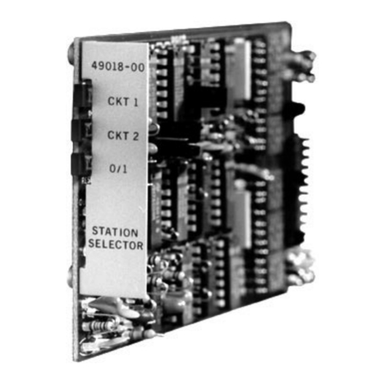
The 49018 subassembly also provides a toll restriction function and a ring generator ground enable output. The 49018 is a plug-in printed circuit subassembly that fits into Dantel’s 44020 DTMF Decoder Module. The front panel consists of three LEDs that indicate the station selected and if the “0” or “1”... -
Page 3: Circuit Description
A busy reset pulse circuit ♦ “0” and “1” digit output drivers In Dantel’s 440 CMS and TMS single station package, the 49018 subassembly BCD address decoder is controlled by BCD inputs from the 44020 DTMF Decoder Module. The 49018 provides buffered outputs for two station addresses. - Page 4 CIRCUIT DESCRIPTION 1 - 49018 F UNCTIONAL CHEMATIC 49018-0697 <90-00089>...
- Page 5 CIRCUIT DESCRIPTION . 2 - 49018 S UBASSEMBLY ODULE ONNECTIONS P2-3 P2-8 CKT 1 OUT RESET IN POWER-UP P2-4 P2-9 CKT 2 OUT CLEAN IN POWER-UP P2-12 P2-5 DIGIT 0 OUT BUSY IN P1-10 P2-6 DIGIT 1 OUT P2-7 BUSY OUT...
- Page 6 The busy latch, when set, provides a ground at P2-7 and applies a reset pulse through the busy reset pulse circuit to clear the 49018 and prepare it to accept the next address. The busy latch remains set until it is cleared by the xternal reset, “Power-up Clear”, or an...
-
Page 7: Application Information
The ground enables the ring generator and the ring/ring back interrupt functions. APPLICATION INFORMATION The 49018 subassembly is mounted to a 44020 DTMF Decoder Module n a 440 CMS or TMS single station package. The 44020 module provides power and all input/output connections to the 49018. - Page 8 APPLICATION INFORMATION . 3 - 49018 S UBASSEMBLY PPLICATION IAGRAM 49018-0697 <90-00089>...
-
Page 9: Installation
INSTALLATION he four straps used on the 49018 subassembly are described below. Refer to Fig. 4 and Table A. . 4 - 49018 S WITCH AND TRAP OCATIONS 49018-00 1 DIGIT CKT 1 2 DIGIT CKT 1 3 DIGIT CKT 2... - Page 10 Verify that the option straps are installed as desired Remove the hole plug from the front panel of the 44020 host module. Insert P1 and P2 of the 49018 subassembly into J1 and J2 of the 44020, ensuring that all the pins go in straight. The subassembly should sit down on the standoffs and appear straight in the 44020’s cutout.
-
Page 11: Operation
44020 in shelf and apply power. OPERATION he 49018 subassembly is operated as an integral part of the 440 system single-package operation. When a station is dialed, verify that CKT#1 or CKT#2 LED comes ON as appropri- ate. -
Page 12: Technical Specifications
3 seconds nominal between digits Reset Strappable for self-clear 3 seconds after decoding, triggered clear from external device or from “*”, “#”, or “C” tone. Physical Dimensions 5.0" x 2.9" x 0.9" Weight 2.2 Oz. Operating Temperature Range 0 to 60° C 49018-0697 <90-00089>... - Page 13 NOTES 49018-0697 <90-00089>...
-
Page 14: Warranty
To ensure expedient processing of your order, provide a purchase order number and shipping and billing information when requesting an RMA number. Also, when the units are returned to Dantel, include a descrip- tion of the failure symptoms for each unit returned. Send defective equipment to: Dantel, Inc.
Need help?
Do you have a question about the 49018 and is the answer not in the manual?
Questions and answers