Table of Contents
Advertisement
Advertisement
Table of Contents
Troubleshooting

Related Manuals for Mitsubishi MELSEC-Q Q62DAN


Summary of Contents for Mitsubishi MELSEC-Q Q62DAN
-
Page 3: Safety Precautions
• SAFETY PRECAUTIONS • (Always read these precautions before using this equipment.) Before using this product, please read this manual and the relevant manuals introduced in this manual carefully and pay full attention to safety to handle the product correctly. The precautions given in this manual are concerned with this product. - Page 4 [INSTALLATION PRECAUTIONS] CAUTION • Use the programmable controller in an environment that meets the general specifications contained in the user's manual of the CPU module to use. Using this programmable controller in an environment outside the range of the general specifications may cause electric shock, fire, malfunction, and damage to or deterioration of the product.
- Page 5 [STARTING AND MAINTENANCE PRECAUTIONS] CAUTION • Do not disassemble or modify the modules. Doing so could cause failure, malfunction injury or fire. • Be sure to shut off all phases of the external power supply used by the system before mounting or removing the module.
-
Page 6: Revisions
REVISIONS The manual number is given on the bottom left of the back cover. Print Date Manual Number Revision Dec., 1999 SH (NA)-080054-A First printing Oct., 2000 SH (NA)-080054-B Add the contents of the function version B. Correction About the Generic Terms and Abbreviations, Section 2.1, Section 3.1.3, 3.3.1, 3.4, Section 4.3, Section 5.2.1, 5.2.2, 5.3.3, 6.5.1 Partial addition Section 1.1, Section 3.1.1, 3.1.2, 3.2.1, 3.2.2, 3.3.1, 3.3.2, 3.4.3,... - Page 7 Print Date Manual Number Revision May, 2002 SH(NA)-080054-F Correction Section 3.4.1, 3.4.2, 3.4.3, 3.4.4, 3.4.6, 3.4.13, 3.4.14, Section 4.5, 4.6, Section 7.3.1, 7.3.2, 7.3.3, 7.3.4, 7.3.5, 7.3.6, 7.4, 7.5, Appendix 1.1, 2.2, 2.3 Partial addition Section 3.3.2, Section 8.2.3 Feb., 2003 SH(NA)-080054-G Correction SAFETY PRECAUTIONS, Section 1.2, Section 3.2, 3.4.1 to 3.4.4,...
- Page 8 This manual confers no industrial property rights or any rights of any other kind, nor does it confer any patent licenses. Mitsubishi Electric Corporation cannot be held responsible for any problems involving industrial property rights which may occur as a result of using the contents noted in this manual.
-
Page 9: Table Of Contents
INTRODUCTION Thank you for purchasing the MELSEC-Q series programmable controller. Before using the equipment, please read this manual carefully to develop full familiarity with the functions and performance of the Q series programmable controller you have purchased, so as to ensure correct use. Please forward a copy of this manual to the end user. - Page 10 3.4.9 Setting range (buffer memory address 20, 21: Un\G20, Un\G21)..........3-29 3.4.10 Offset/gain setting mode and offset/gain specification (buffer memory addresses 22, 23: Un\G22, Un\G23) ............. 3-29 3.4.11 Setting value specification (buffer memory address 24: Un\G24) ..........3-29 3.4.12 Mode switching setting (buffer memory addresses 158, 159: Un\G158, Un\G159) ....3-30 3.4.13 Pass data classification setting (buffer memory addresses 200: Un\G200) (Q62DAN, Q64DAN, Q62DA, Q64DA only) ..............
- Page 11 6.2 For Use on Remote I/O Network ......................6- 6 6.2.1 Programming example using the utility package................6- 7 6.2.2 Programming example without using the utility package.............. 6-10 7 ONLINE MODULE CHANGE 7- 1 to 7-36 7.1 Online Module Change Conditions......................7- 2 7.2 Online Module Change Operations ......................
-
Page 12: About Manuals
(1) For programmable controller system To configure a system meeting the requirements of the EMC and Low Voltage Directives when incorporating the Mitsubishi programmable controller (EMC and Low Voltage Directives compliant) into other machinery or equipment, refer to Chapter 9 "EMC AND LOW VOLTAGE DIRECTIVES" of the QCPU User's Manual (Hardware Design, Maintenance and Inspection). -
Page 13: About The Generic Terms And Abbreviations
About the Generic Terms and Abbreviations Unless otherwise specified, this manual uses the following generic terms and abbreviations. Abbreviation/general terms Description of the abbreviation/general terms Generic term for Q62DAN, Q64DAN, Q68DAVN, Q68DAIN, Q62DA, Q64DA, Q68DAV, D/A converter module Q68DAI. ® DOS/V personal computer IBM PC/AT or compatible computer with DOS/V. -
Page 14: Product Structure
Product Structure The product structure of this product is given in the table below. Model code Product name Quantity Q62DAN Q62DAN Model Digital-Analog Converter module Q64DAN Q64DAN Model Digital-Analog Converter module Q68DAVN Model Digital-Analog Converter module Q68DAVN FG terminal L-Shaped metal fitting Q68DAIN Model Digital-Analog Converter module Q68DAIN FG terminal L-Shaped metal fitting... -
Page 15: Overview
1 OVERVIEW MELSEC-Q 1 OVERVIEW This User's Manual provides the specifications, handling instructions and programming methods for the following digital-analog converter modules that are used in combination with MELSEC-Q series CPU modules (hereinafter referred to as programmable controller CPU). • Q62DAN type digital-analog converter module (hereinafter referred to as the Q62DAN) •... - Page 16 1 OVERVIEW MELSEC-Q (8) Analog output HOLD/CLEAR function This function is set to either retain or clear the analog output value when the CPU module is in the STOP status or when a stop error occurs. (9) Easy settings using the utility package A utility package is sold separately (GX Configurator-DA).
-
Page 17: Functions Added To Function Version B And Later
1 OVERVIEW MELSEC-Q 1.2 Functions Added to Function Version B and Later (1) Functions added to function version B D/A converter module The functions added by the function version B D/A converter module are listed below. Item Function overview Reference section Compatible with a Multiple CPU system. - Page 18 1 OVERVIEW MELSEC-Q MEMO 1 - 4 1 - 4...
-
Page 19: System Configuration
2 SYSTEM CONFIGURATION MELSEC-Q 2 SYSTEM CONFIGURATION This chapter explains the system configuration of the D/A converter module. 2.1 Applicable Systems This section describes the applicable systems. (1) Applicable modules and base units, and No. of modules When mounted with a CPU module The table below shows the CPU modules and base units applicable to the D/A converter module and quantities for each CPU model. - Page 20 2 SYSTEM CONFIGURATION MELSEC-Q Base unit Applicable CPU module No. of modules CPU type CPU model Main base unit Extension base unit Q06CCPU-V C Controller module Up to 64 Q06CCPU-V-B : Applicable, : N/A 1 Limited within the range of I/O points for the CPU module. 2 Can be installed to any I/O slot of a base unit.
- Page 21 2 SYSTEM CONFIGURATION MELSEC-Q (3) Compatibility with online module change To make an online module change, use the module of function version C or later. POINT The products of function version C include the functions of the products of function versions A and B.
-
Page 22: Precautions On System Configuration
2 SYSTEM CONFIGURATION MELSEC-Q 2.2 Precautions on System Configuration (1) For Use with Q12PRH/Q25PRHCPU Dedicated instruction The dedicated instruction cannot be used. GX Configurator-DA connection GX Configurator-DA cannot be used when accessing the Q12PRH/Q25PRHCPU via an intelligent function module on an extension base unit from GX Developer. -
Page 23: How To Check The Function Version And Software Version
2 SYSTEM CONFIGURATION MELSEC-Q 2.3 How to Check the Function Version and Software Version This section describes how to check the function version of the D/A converter module and the GX Configuration-DA software version. (1) Checking the function version of the D/A converter module (a) Checking at "the SERIAL field of the rating plate"... - Page 24 2 SYSTEM CONFIGURATION MELSEC-Q REMARK The version indication for the GX Configurator-DA has been changed as shown below from the SW0D5C-QDAU-E 60G upgrade product. Previous product Upgrade and subsequent versions SW0D5C-QDAU-E 60G GX Configurator-DA Version 1.10L 2 - 6 2 - 6...
-
Page 25: Specifications
3 SPECIFICATIONS MELSEC-Q 3 SPECIFICATIONS 3.1 Performance Specifications 3.1.1 Performance specifications list (1) Q62DAN, Q64DAN, Q68DAVN, Q68DAIN Table 3.1 Performance specifications list Model name Q62DAN Q64DAN Q68DAVN Q68DAIN Item Number of analog output points 2 points (2 channels) 4 points (4 channels) 8 points (8 channels) 16-bit signed binary (normal resolution mode: -4096 to 4095, Digital input... - Page 26 3 SPECIFICATIONS MELSEC-Q (2) Q62DA, Q64DA, Q68DAV, Q68DAI Table 3.2 Performance specifications list Model name Q62DA Q64DA Q68DAV Q68DAI Item Number of analog output points 2 points (2 channels) 4 points (4 channels) 8 points (8 channels) 16-bit signed binary (normal resolution mode: -4096 to 4095, Digital input high resolution mode: -12288 to 12287, -16384 to 16383) Voltage...
-
Page 27: I/O Conversion Characteristics
3 SPECIFICATIONS MELSEC-Q When the voltage of the external power supply is less than 22.85V DC, the analog output current and the external load resistance value are as follows. External power supply 22.85V to 28.8V 18.5 17.3 20.4V 16.5 (mA) External load resistance value( ) REMARK See the user's manual for the CPU module being used for the general specifications... - Page 28 3 SPECIFICATIONS MELSEC-Q (1) Voltage output characteristic (a) Voltage output characteristic in normal resolution mode Figure 3.1 shows a graph of the voltage output characteristic in normal resolution mode. 4095 -4096 -4000 -2000 2000 4000 Digital input value Maximum Number Output range setting Offset value Gain value Digital input value resolution...
- Page 29 3 SPECIFICATIONS MELSEC-Q (b) Voltage output characteristic in high resolution mode Figure 3.2 shows a graph of the voltage output characteristic in high resolution mode. -16384 -16000 -8000 8000 12000 16000 16383 12287 Digital input value Maximum Number Output range setting Offset value Gain value Digital input value resolution...
- Page 30 3 SPECIFICATIONS MELSEC-Q POINT (1) Set within the digital input range and analog output range for each output range. If these ranges are exceeded, the maximum resolution and accuracy may not fall within the performance specifications. (Avoid using the dotted line area shown in Figures 3.1 and 3.2.) (2) Set the offset/gain values for the user setting range 1 within a range in which...
- Page 31 3 SPECIFICATIONS MELSEC-Q (2) Current output characteristic (a) Current output characteristic in normal resolution mode Figure 3.3 shows a graph of the current output characteristic in normal resolution mode. 2000 4000 4095 Digital input value Maximum Number Output range setting Offset value Gain value Digital input value resolution...
- Page 32 3 SPECIFICATIONS MELSEC-Q (b) Current output characteristic in high resolution mode Figure 3.4 shows a graph of the current output characteristic in high resolution mode. 6000 12000 12287 Digital input vaule Maximum Number Output range setting Offset value Gain value Digital input value resolution 1.66...
- Page 33 3 SPECIFICATIONS MELSEC-Q POINT (1) Set within the digital input range and analog output range for each output range. If these ranges are exceeded, the maximum resolution and accuracy may not fall within the performance specifications. (Avoid using the dotted line area shown in Figures 3.3 and 3.4.) (2) Set the offset/gain values for the user setting range 1 within a range in which...
-
Page 34: Accuracy
3 SPECIFICATIONS MELSEC-Q 3.1.3 Accuracy Accuracy is represented with respect to the maximum analog output value. Accuracy does not change and remains within the range listed in the performance specification even if the output characteristic is changed by changing offset/gain settings, output range and resolution mode. -
Page 35: D/A Converter Module Function
3 SPECIFICATIONS MELSEC-Q 3.2 D/A Converter Module Function Table 3.3 shows the function of the D/A converter modules. Table 3.3 Function list Item Function Reference section (1) Specifies whether to enable or disable the D/A conversion for each channel. D/A conversion enable/disable (2) By disabling the D/A conversion for the channels that are not used, the conversion speed can be Section 3.4.4 function... -
Page 36: Analog Output Hold/Clear Function
3 SPECIFICATIONS MELSEC-Q 3.2.2 Analog output HOLD/CLEAR function (1) For the case where the programmable controller CPU is placed in STOP or in a stop error status, whether to hold (HOLD) or clear (CLEAR) the analog output value can be set. (2) Make the setting in the HOLD/CLEAR setting (Refer to Section 4.5(1)). -
Page 37: Analog Output Test During Programmable Controller Cpu Stop
3 SPECIFICATIONS MELSEC-Q 3.2.3 Analog output test during programmable controller CPU STOP (1) During the programmable controller CPU STOP, an analog output test as shown in Table 3.5 can be performed. (2) The analog output test performs the following operations in GX Developer device testing or GX configurator-DA selection testing described in Section 5.6.1. -
Page 38: I/O Signals For The Programmable Controller Cpu
3 SPECIFICATIONS MELSEC-Q 3.3 I/O Signals for the Programmable Controller CPU 3.3.1 List of I/O signals Table 3.6 shows a list of the I/O signals for the D/A converter modules. The following explanation is mentioned based on the Q68DAVN, Q68DAIN, Q68DAV and Q68DAI with 8-channel analog output (CH1 to CH8). -
Page 39: Details Of I/O Signals
3 SPECIFICATIONS MELSEC-Q 3.3.2 Details of I/O signals I/O signals for the D/A converter module are explained in detail below. (1) Input signals Device No. Signal name Description (1) When the programmable controller CPU is powered on or reset, this signal turns on once the preparation for D/A conversion has been completed, and D/A conversion processing is then performed. - Page 40 3 SPECIFICATIONS MELSEC-Q Device No. Signal name Description [In offset/gain setting mode] (1) This is used as an interlock condition for setting the user range write request (YA) to ON/OFF when registering the value after adjustment of the offset/gain settings have been completed.
- Page 41 3 SPECIFICATIONS MELSEC-Q Device No. Signal name Description (1) This is used as an interlock condition for setting the set value change request (YC) to ON/OFF when adjusting the offset/gain settings. (2) See Section 4.6 regarding the offset and gain settings. Performed by the D/A converter module Set value change Performed by the sequence program...
- Page 42 3 SPECIFICATIONS MELSEC-Q (2) Output signals Device No. Signal name Description (1) Specifies whether to output the D/A converted value or offset value for each channel. output Y1 to Y8 ON: D/A converted value OFF: Offset value enable/disable flag (2) The D/A conversion speed is constant regardless of whether the output enable/disable flag is ON or OFF.
-
Page 43: Buffer Memory
3 SPECIFICATIONS MELSEC-Q 3.4 Buffer Memory The explanation in Section 3.4.5 and later is based on the 8-channel analog output (CH1 to CH8) Q68DAVN/Q68DAIN/Q68DAV/Q68DAI. 3.4.1 Buffer memory assignment (Q62DAN/Q62DA) This section describes the assignment of the Q62DAN/Q62DA buffer memory. POINT Do not write data from system area or sequence program to the buffer memory area where writing is disabled. - Page 44 3 SPECIFICATIONS MELSEC-Q Table 3.7 Buffer memory assignment (Q62DAN/Q62DA) (2/2) Address Default Read/write Description Hexadecimal Decimal Pass data classification setting System area — — CH1 Industrial shipment settings offset value CH1 Industrial shipment settings gain value CH2 Industrial shipment settings offset value CH2 Industrial shipment settings gain value CH1 User range settings offset value CH1 User range settings gain value...
-
Page 45: Buffer Memory Assignment (Q64Dan/Q64Da)
3 SPECIFICATIONS MELSEC-Q 3.4.2 Buffer memory assignment (Q64DAN/Q64DA) This section describes the assignment of the Q64DAN/Q64DA buffer memory. POINT Do not write data from system area or sequence program to the buffer memory area where writing is disabled. Doing so may cause malfunction. Table 3.8 Buffer memory assignment (Q64DAN/Q64DA) (1/2) Address Description... - Page 46 3 SPECIFICATIONS MELSEC-Q Table 3.8 Buffer memory assignment (Q64DAN/Q64DA) (2/2) Address Description Default Read/write Hexadecimal Decimal Pass data classification setting System area — — CH1 Industrial shipment settings offset value CH1 Industrial shipment settings gain value CH2 Industrial shipment settings offset value CH2 Industrial shipment settings gain value CH3 Industrial shipment settings offset value CH3 Industrial shipment settings gain value...
-
Page 47: Buffer Memory Assignment (Q68Davn/Q68Dav)
3 SPECIFICATIONS MELSEC-Q 3.4.3 Buffer memory assignment (Q68DAVN/Q68DAV) This section describes the assignment of the Q68DAVN/Q68DAV buffer memory. POINT Do not write data from system area or sequence program to the buffer memory area where writing is disabled. Doing so may cause malfunction. Table 3.9 Buffer memory assignment (Q68DAVN/Q68DAV) (1/2) Address Description... - Page 48 3 SPECIFICATIONS MELSEC-Q Table 3.9 Buffer memory assignment (Q68DAVN/Q68DAV) (2/2) Address Description Default Read/write Hexadecimal Decimal System area — — Mode switching setting System area — — CH1 Industrial shipment settings offset value CH1 Industrial shipment settings gain value CH2 Industrial shipment settings offset value CH2 Industrial shipment settings gain value CH3 Industrial shipment settings offset value CH3 Industrial shipment settings gain value...
-
Page 49: Buffer Memory Assignment (Q68Dain/Q68Dai)
3 SPECIFICATIONS MELSEC-Q 3.4.4 Buffer memory assignment (Q68DAIN/Q68DAI) The following explanation is mentioned based on Q68DAIN/Q68DAI with 8-channel analog output (CH1 to CH8). POINT Do not write data from system area or sequence program to the buffer memory area where writing is disabled. Doing so may cause malfunction. Table 3.10 Buffer memory assignment (Q68DAIN/Q68DAI) (1/2) Address Description... - Page 50 3 SPECIFICATIONS MELSEC-Q Table 3.10 Buffer memory assignment (Q68DAIN/Q68DAI) (2/2) Address Description Default Read/write Hexadecimal Decimal System area — — Mode switching setting System area — — CH1 Industrial shipment settings offset value CH1 Industrial shipment settings gain value CH2 Industrial shipment settings offset value CH2 Industrial shipment settings gain value CH3 Industrial shipment settings offset value CH3 Industrial shipment settings gain value...
-
Page 51: D/A Conversion Enable/Disable (Buffer Memory Address 0: Un\G0)
3 SPECIFICATIONS MELSEC-Q 3.4.5 D/A conversion enable/disable (buffer memory address 0: Un\G0) (1) Set whether D/A conversion is enabled or disabled for each channel. (2) It is necessary to set the operating condition setting request (Y9) to ON/OFF to validate the D/A conversion enable/disable setting. (See Section 3.3.2.) (3) By default, all channels are set to D/A conversion disabled. -
Page 52: Set Value Check Codes (Buffer Memory Addresses 11 To 18: Un\G11 To Un\G18)
3 SPECIFICATIONS MELSEC-Q 3.4.7 CH set value check codes (buffer memory addresses 11 to 18: Un\G11 to Un\G18) (1) This area stores the result of checking whether a digital value that was set is within or outside the valid range. (2) When a digital value outside the valid range (see Table 3.11) is written, one of the check codes listed in Table 3.12 is stored. -
Page 53: Setting Range (Buffer Memory Address 20, 21: Un\G20, Un\G21)
3 SPECIFICATIONS MELSEC-Q 3.4.9 Setting range (buffer memory address 20, 21: Un\G20, Un\G21) (1) This area is used to confirm the setting range of the D/A converter module. Settings for channels 1 to 4 are stored in Un\G20. Settings for channels 5 to 8 are stored in Un\G21. (2) For Q62DAN, Q62DA, b8 to b15 (CH3 and 4 information) for Un\G20 and Un\G21 (information of CH5 to CH8) are invalid. -
Page 54: Mode Switching Setting (Buffer Memory Addresses 158, 159: Un\G158, Un\G159)
3 SPECIFICATIONS MELSEC-Q 3.4.12 Mode switching setting (buffer memory addresses 158, 159: Un\G158, Un\G159) (1) Set the values of the mode to which you want to switch. (2) After setting the values, turning the operation condition setting request (Y9) from OFF to ON switches to that mode. -
Page 55: Industrial Shipment Settings And User Range Settings Offset/Gain Values
3 SPECIFICATIONS MELSEC-Q 3.4.14 Industrial shipment settings and user range settings offset/gain values (buffer memory addresses 202 to 233: Un\G202 to Un\G233) (1) Areas used to restore the user range settings offset/gain values when online module change is made. Refer to chapter 7 for details of online module change. (2) When the offset/gain values of the user range setting are restored, the used data are stored. -
Page 56: Setup And Procedures Before Operation
4 SETUP AND PROCEDURES BEFORE OPERATION MELSEC-Q 4 SETUP AND PROCEDURES BEFORE OPERATION 4.1 Handling Precautions (1) Do not drop the module case or subject it to heavy impact. (2) Do not remove the PCB of the module from its case. Doing so may cause the module to fail. - Page 57 4 SETUP AND PROCEDURES BEFORE OPERATION MELSEC-Q 4.2 Setup and Procedures before Operation Start Module mounting Mount the D/A converter module in the specified slot. Wiring Wire external devices to the D/A converter module. Intelligent functional module switch settings Perform settings using GX Developer (see Section 4.5).
-
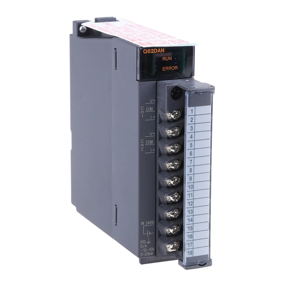
Page 58: Part Identification Nomenclature
4 SETUP AND PROCEDURES BEFORE OPERATION MELSEC-Q 4.3 Part Identification Nomenclature This section explains each part name of the D/A converter module, providing examples of the Q62DAN, Q64DAN, Q68DAVN and Q68DAIN. Differences between the Q62DAN/Q64DAN/Q68DAVN/Q68DAIN and Q62DA/Q64DA/Q68DAV/Q68DAI are model names and external dimensions only. For details, refer to Appendix 3 External Dimension Diagram. - Page 59 4 SETUP AND PROCEDURES BEFORE OPERATION MELSEC-Q Signal name Terminal number Q62DAN, Q62DA Q64DAN, Q64DA Q68DAVN, Q68DAV Q68DAIN, Q68DAI Vacant Vacant Vacant Vacant Vacant Vacant Vacant Vacant Vacant Vacant Vacant Vacant 4 - 4 4 - 4...
-
Page 60: Wiring
4 SETUP AND PROCEDURES BEFORE OPERATION MELSEC-Q 4.4 Wiring The wiring precautions and examples of module connection are provided below. 4.4.1 Wiring precautions In order to optimize the functions of the D/A converter module and ensure system reliability, external wiring that is protected from noise is required. Please observe the following precautions for external wiring: (1) Use separate cables for the AC control circuit and the external input signals of the D/A converter module to avoid the influence of the AC side surges and inductions. -
Page 61: External Wiring
4 SETUP AND PROCEDURES BEFORE OPERATION MELSEC-Q 4.4.2 External wiring (1) For voltage output of Q62DAN or Q64DAN, or Q68DAVN Motor drive module, etc. conversion 24 V DC DC/DC Filter converter 1 Use a twisted two core shielded wire for the power wire. 2 If there is noise or ripples in the external wiring, connect a 0.1 to 0.47 F 25V capacitor between the V+ terminal and COM. - Page 62 4 SETUP AND PROCEDURES BEFORE OPERATION MELSEC-Q (3) For voltage output of Q62DA or Q64DA, or Q68DAV Motor drive module, etc. conversion 24 V DC DC/DC Filter converter 1 Use a twisted two core shielded wire for the power wire. 2 If there is noise or ripples in the external wiring, connect a 0.1 to 0.47 F 25V capacitor between the V+ terminal and COM.
-
Page 63: Switch Setting For Intelligent Function Module
4 SETUP AND PROCEDURES BEFORE OPERATION MELSEC-Q 4.5 Switch Setting for Intelligent Function Module The settings for the intelligent function module are performed using the I/O assignment settings of GX Developer. (1) Setting item The intelligent function module switches consist of switches 1 to 5 and are set using 16 bit data. - Page 64 4 SETUP AND PROCEDURES BEFORE OPERATION MELSEC-Q POINT (1) Depending on the type of module used, the settings for D/A module output range are shown below. • Q62DAN, Q64DAN, Q62DA, Q64DA ..0 to 4 • Q68DAVN, Q68DAV........ 0 to 4 1 When the setting is 0 , the output operating range swill be 1 to 5 V.
- Page 65 4 SETUP AND PROCEDURES BEFORE OPERATION MELSEC-Q (2) Operating procedure Start the settings with GX Developer I/O assignment setting screen. (a) I/O assignment setting screen Set the following for the slot in which the D/A converter module is mounted. The type setting is required; set other items as needed. Type : Select "intelli."...
- Page 66 4 SETUP AND PROCEDURES BEFORE OPERATION MELSEC-Q (b) Switch setting for intelligent function module screen Click on [Switch setting] on the I/O assignment setting screen to display the screen shown at the left, then set switches 1 to 5. The switches can easily be set if values are entered in hexadecimal. Change the entry format to hexadecimal and then enter the values.
-
Page 67: Offset/Gain Settings
4 SETUP AND PROCEDURES BEFORE OPERATION MELSEC-Q 4.6 Offset/Gain Settings When the user range setting is used, perform the offset and gain settings according to the following procedure. When the industrial shipment setting is used, offset/gain setting is not necessary. If the utility package is installed, perform the offset/gain settings according to the procedure described in Section 5.6.2. - Page 68 4 SETUP AND PROCEDURES BEFORE OPERATION MELSEC-Q 1 The mode switching (normal mode to offset/gain setting mode to normal mode) method is given below. • Dedicated instruction (G(P).OFFGAN) ..Refer to Section 4.6 (2), (a) • Setting made to mode switching setting (buffer memory addresses 158, 159: Un\G158, Un\G159) and turning the operation condition setting request (Y9) from OFF to ON .............
- Page 69 4 SETUP AND PROCEDURES BEFORE OPERATION MELSEC-Q (2) Program examples The program in the dotted area of (a) is common to (a), (b) and (c). In this example, the I/O signals for the D/A converter module are X/Y0 to X/YF. •...
- Page 70 4 SETUP AND PROCEDURES BEFORE OPERATION MELSEC-Q (a) When switching the mode using the dedicated instruction (G(P).OFFGAN) The following sample program switches to the offset/gain setting mode with the dedicated instruction (G(P).OFFGAN), changes the channel where offset/gain setting will be made, adjusts the offset/gain values, and writes the offset/gain values to the D/A converter module.
- Page 71 4 SETUP AND PROCEDURES BEFORE OPERATION MELSEC-Q (b) When switching the mode using the setting of the mode switching setting (buffer memory addresses 158, 159: Un\G158, Un\G159) and operation condition setting request (Y9) Normal mode initial setting D/A conversion enable/disable setting Turns ON operation condition setting request (Y9).
- Page 72 4 SETUP AND PROCEDURES BEFORE OPERATION MELSEC-Q MEMO 4 - 17 4 - 17...
-
Page 73: Utility Package (Gx Configurator-Da)
5 UTILITY PACKAGE (GX Configurator-DA) MELSEC-Q 5 UTILITY PACKAGE (GX Configurator-DA) 5.1 Utility Package Functions Table 5.1 shows an overview of the utility package functions. Table 5.1 Utility package (GX Configurator-DA) function list Item Description Reference section (1) Sets the D/A conversion enable/disable. (2) The data for which initial setting has been completed is registered in Initial Setting the parameters for the programmable controller CPU, and... -
Page 74: Installing And Uninstalling The Utility Package
5 UTILITY PACKAGE (GX Configurator-DA) MELSEC-Q 5.2 Installing and Uninstalling the Utility Package For how to install or uninstall the utility package, refer to "Method of installing the MELSOFT Series" included in the utility package. 5.2.1 Handling precautions The following explains the precautions on using the GX Configurator-DA. (1) For safety Since GX Configurator-DA is add-in software for GX Developer, read "Safety Precautions"... - Page 75 5 UTILITY PACKAGE (GX Configurator-DA) MELSEC-Q (6) Number of parameters that can be set in GX Configurator-DA When multiple intelligent function modules are mounted, the number of parameter setting must not exceed the following limit. Maximum number of parameter settings When intelligent function modules are installed to: Initial setting Auto refresh setting...
-
Page 76: Operating Environment
5 UTILITY PACKAGE (GX Configurator-DA) MELSEC-Q 5.2.2 Operating environment This section explains the operating environment of the personal computer that runs GX Configurator-DA. Item Description Installation (Add-in) target Add-in to GX Developer Version 4 (English version) or later Computer Windows -based personal computer Refer to the following table "Operating system and performance required for personal computer". - Page 77 5 UTILITY PACKAGE (GX Configurator-DA) MELSEC-Q Operating system and performance required for personal computer Performance required for personal computer Operating system Memory Windows Pentium 133MHz or more 32MB or more Windows Pentium 133MHz or more 32MB or more Windows Pentium 150MHz or more 32MB or more Windows NT...
-
Page 78: Utility Package Operation
5 UTILITY PACKAGE (GX Configurator-DA) MELSEC-Q 5.3 Utility Package Operation 5.3.1 Common utility package operations (1) Control keys Special keys that can be used for operation of the utility package and their applications are shown in the table below. Application Cancels the current entry in a cell. - Page 79 5 UTILITY PACKAGE (GX Configurator-DA) MELSEC-Q (2) Data created with the utility package The following data or files that are created with the utility package can be also handled in GX Developer. Figure 5.1 shows respective data or files are handled in which operation.
- Page 80 5 UTILITY PACKAGE (GX Configurator-DA) MELSEC-Q <Text files> (a) A text file can be created by clicking the Make text file button on the initial setting, Auto refresh setting, or Monitor/Test screen. The text files can be utilized to create user documents. GX Developer/ GX Configurator-DA Disk...
-
Page 81: Operation Overview
5 UTILITY PACKAGE (GX Configurator-DA) MELSEC-Q 5.3.2 Operation overview GX Developer screen [Tools] [Intelligent function utility] [Start] Screen for selecting a target intelligent function module Refer to Section 5.3.3. Enter "Start I/O No.", and select "Module type" and "Module model name". Initial setting Auto refresh Auto refresh setting screen... - Page 82 5 UTILITY PACKAGE (GX Configurator-DA) MELSEC-Q [Online] [Monitor/Test] <<FB support parameter>> tab FB conversion Selecting monitor/test module screen FB conversion screen Refer to Section 5.7. Select a module to be monitored/tested. Monitor/Test Refer to Section 5.6. 5 - 10 5 - 10...
-
Page 83: Starting The Intelligent Function Module Utility
5 UTILITY PACKAGE (GX Configurator-DA) MELSEC-Q 5.3.3 Starting the Intelligent function module utility [Operating procedure] Intelligent function module utility is started from GX Developer. [Tools] [Intelligent function utility] [Start] [Setting screen] Display when the <<FB support parameter>> tab is selected. [Explanation of items] (1) Activation of other screens Following screens can be displayed from the intelligent function module utility... - Page 84 5 UTILITY PACKAGE (GX Configurator-DA) MELSEC-Q POINT The <<FB support parameter>> tab is displayed when the project which is being edited is a label project. (2) Command buttons Common operations to the <<Intelligent function module parameter>> tab and <<FB support parameter>> tab Deletes the initial setting and auto refresh setting of the selected Delete module.
- Page 85 5 UTILITY PACKAGE (GX Configurator-DA) MELSEC-Q POINT (1) Saving intelligent function module parameters in a file Since intelligent function module parameters cannot be saved in a file by the project saving operation of GX Developer, save them on the shown module selection screen for intelligent function module parameter setting.
-
Page 86: Initial Setting
5 UTILITY PACKAGE (GX Configurator-DA) MELSEC-Q 5.4 Initial Setting [Purpose] Set D/A conversion enable/disable with an initial setting parameter. The initial setting parameter eliminates the need to set D/A conversion enable/disable in the sequence program. [Operating procedure] "Start I/O No. " "Module type"... -
Page 87: Auto Refresh Setting
5 UTILITY PACKAGE (GX Configurator-DA) MELSEC-Q 5.5 Auto Refresh Setting [Purpose] Configure the D/A converter module's buffer memory for automatic refresh. [Operating procedure] "Start I/O No. " "Module type" "Module model name" Auto refresh Enter the start I/O No. in hexadecimal. [Setting screen] [Items] (1) Contents of the screen display... - Page 88 5 UTILITY PACKAGE (GX Configurator-DA) MELSEC-Q (2) Command button Make text file Creates a file containing the screen data in text file format. End setup Saves the set data and ends the operation. Cancel Cancels the setting and ends the operation. POINT The auto refresh settings are stored in an intelligent function module parameter file.
-
Page 89: Monitor/Test
5 UTILITY PACKAGE (GX Configurator-DA) MELSEC-Q 5.6 Monitor/Test 5.6.1 Monitor/test screen [Purpose] Start buffer memory monitoring/testing and I/O signal monitoring/testing, operating condition setting, offset/gain settings (refer to Section 5.6.2, 5.6.3), pass data (refer to Section 5.6.5, 5.6.6)from this screen. [Operating procedure] Select monitor/test module screen "Start I/O No. - Page 90 5 UTILITY PACKAGE (GX Configurator-DA) MELSEC-Q Pass data Operating setting Offset/gain setting Conversion characteristic 5 - 18 5 - 18...
- Page 91 5 UTILITY PACKAGE (GX Configurator-DA) MELSEC-Q [Explanation of items] (1) Items Setting item : Displays buffer memory names. Current value : Monitors the present buffer memory values. Setting value : Enter or select values to be written into the buffer memory for test operation.
-
Page 92: Offset/Gain Setting Operation (Function Version C Or Later)
5 UTILITY PACKAGE (GX Configurator-DA) MELSEC-Q 5.6.2 Offset/gain setting operation (Function version C or later) Perform the offset/gain setting operation in the following sequence. (1) Switch to the offset/gain setting screen Perform the operation in Section 5.6.1 to display the offset/gain setting screen. At this point, a dialog box to confirm the transition of module's operation mode (normal mode ->... - Page 93 5 UTILITY PACKAGE (GX Configurator-DA) MELSEC-Q (5) Fine adjustment of voltage output or current output By clicking the + button or - button, the value of voltage output or current output for the prepared adjustment value is finely adjusted. (6) Write settings into module Write the content set up by operations (2) to (5) into module by clicking the Registration button.
-
Page 94: Offset/Gain Setting Operation (Function Version B Or Earlier)
5 UTILITY PACKAGE (GX Configurator-DA) MELSEC-Q 5.6.3 Offset/gain setting operation (Function version B or earlier) Perform the offset/gain setting operation in the following sequence. (1) Switch to the offset/gain setting mode Change switch 4 for intelligent function module switch setting to the offset/gain setting mode (see Section 4.5). - Page 95 5 UTILITY PACKAGE (GX Configurator-DA) MELSEC-Q (6) Fine adjustment of voltage output or current output By clicking the + button or - button, the value of voltage output or current output for the prepared adjustment value is finely adjusted. (7) Write settings into module Write the content set up by operations (3) to (6) into module by clicking the Registration button.
-
Page 96: Confirmation Of Conversion Characteristic
5 UTILITY PACKAGE (GX Configurator-DA) MELSEC-Q 5.6.4 Confirmation of Conversion Characteristic [Purpose] The converted value of digital-analog conversion can be confirmed according to the tilt of the graph, based on the offset/gain setting. [Operating procedure] Monitor/Test screen Offset/gain setting Conversion characteristic [Setting screen] [Explanation of items] (1) Items... - Page 97 5 UTILITY PACKAGE (GX Configurator-DA) MELSEC-Q Analog/Digital conversion: Select a conversion type shown below for confirming the correspondence between an analog value and a digital value caused by the conversion characteristic. • Digital Analog • Analog Digital Analog value: <When converted to a digital value> Enter an analog value to be converted to a digital value <When converted to an analog value>...
-
Page 98: Pass Data (Q62Dan/Q64Dan/Q62Da/Q64Da)
5 UTILITY PACKAGE (GX Configurator-DA) MELSEC-Q 5.6.5 Pass data (Q62DAN/Q64DAN/Q62DA/Q64DA) Perform operation in the following sequence to save/restore the user range. (1) Switch to the pass data screen Perform the operation in Section 5.6.1 to display the Pass data screen. (2) User range saving (a) Set "Voltage specified"... - Page 99 5 UTILITY PACKAGE (GX Configurator-DA) MELSEC-Q (3) User range restoration (a) Set "Voltage specified" or "Current specified" in the Setting value field of Pass data classification setting, and click the Execute test button. When the setting is completed, the set data is displayed in the Current value field of CH Pass data classification setting.
-
Page 100: Pass Data (Q68Davn/Q68Dain/Q68Dav/Q68Dai)
5 UTILITY PACKAGE (GX Configurator-DA) MELSEC-Q 5.6.6 Pass data (Q68DAVN/Q68DAIN/Q68DAV/Q68DAI) Perform operation in the following sequence to save/restore the user range. (1) Switch to the Pass data screen Perform the operation in Section 5.6.1 to display the pass data screen. (2) User range saving (a) Change the Setting value field of Pass data read request to "Request", and click the Execute test button. -
Page 101: Fb Conversion Of Initial Setting/Auto Refresh Setting
5 UTILITY PACKAGE (GX Configurator-DA) MELSEC-Q 5.7 FB Conversion of Initial Setting/Auto Refresh Setting [Purpose] FB is generated automatically from the intelligent function module parameter (initial setting/auto refresh setting). [Operating procedure] Intelligent Function Module Parameter Setting Module Selection Screen <<FB Support Parameter>> FB conversion [Setting screen] [Explanation of items]... -
Page 102: Usage Of Fb
5 UTILITY PACKAGE (GX Configurator-DA) MELSEC-Q 5.8 Usage of FB This section describes the procedure for using FB with GX Developer. Refer to the "GX Developer Version 8 Operating Manual (Function Block)" for details. 5.8.1 Outline The procedure for creating FB is shown below. (1) Set up the intelligent function module parameter (initial setting/auto refresh setting). - Page 103 5 UTILITY PACKAGE (GX Configurator-DA) MELSEC-Q POINT The initial setting/auto refresh setting of the intelligent function module can be performed by each of the following methods. (1) Set intelligent function parameters (Initial setting/Auto refresh setting) and write them to the programmable controller CPU. (2) Create an FB of the intelligent function module parameter (initial setting/auto refresh setting) and paste it to the sequence program.
-
Page 104: Paste An Fb To A Sequence Program
5 UTILITY PACKAGE (GX Configurator-DA) MELSEC-Q 5.8.2 Paste an FB to a Sequence Program [Purpose of operation] Paste an FB in order to use it with a sequence program. [Operation procedure] Switch the <<Project>> tab into the <<FB>> tab on GX Developer, and drag & drop the FB to be used onto the sequence program. -
Page 105: Convert (Compile) A Sequence Program
5 UTILITY PACKAGE (GX Configurator-DA) MELSEC-Q 5.8.3 Convert (Compile) a Sequence Program [Purpose of operation] Convert (compile) the sequence program to which an FB was pasted so that it can be executed. [Operation procedure] Click the [Convert] menu [Convert/Compile] menu of GX Developer. 5 - 33 5 - 33... - Page 106 5 UTILITY PACKAGE (GX Configurator-DA) MELSEC-Q MEMO 5 - 34 5 - 34...
-
Page 107: Programming
6 PROGRAMMING MELSEC-Q 6 PROGRAMMING This chapter describes the programs of the D/A converter module. When applying any of the program examples introduced in this chapter to the actual system, verify the applicability and confirm that no problems will occur in the system control. -
Page 108: Programming Example Using The Utility Package
6 PROGRAMMING MELSEC-Q 6.1.1 Programming example using the utility package (1) Operating the utility package (a) Initial setting (see Section 5.4.) CH1, CH2 D/A conversion enable/disable setting .."Enable" (b) Automatic refresh setting (see Section 5.5.) CH1, CH2 Digital value .."D11, D12" Error code ...... - Page 109 6 PROGRAMMING MELSEC-Q (2) Programming example Digital value write program Write the digital values for CH1and CH2 in D11 and D12 that have been automatically refreshed. Set analog output to enable Enables analog output for CH1 and CH2. Error code display and reset processing Output the error code to Y20 to Y2B by BCD code.
-
Page 110: Programming Example Without Using The Utility Package
6 PROGRAMMING MELSEC-Q 6.1.2 Programming example without using the utility package (1) Programming example using the FROM/TO commands Set the D/A conversion enabled channel (initial setting). Set CH1 and CH2 to D/A conversion enable. Set Y9 (operating condition setting request) from ON to OFF to validate the initial setting. - Page 111 6 PROGRAMMING MELSEC-Q (2) Programming example using the intelligent function module device (U \G ) Set the D/A conversion enabled channel (initial setting) Set CH1 and CH2 to D/A conversion enable. Set Y9 (operating condition setting request) from ON to OFF to validate the initial setting.
-
Page 112: For Use On Remote I/O Network
6 PROGRAMMING MELSEC-Q 6.2 For Use on Remote I/O Network System configuration used in the program explanation (1) System configuration Remote master station (Network No.1) Remote I/O station (Station No.1) Power Power supply supply module module X/Y100 X/Y110 X/Y120 X/Y10F X/Y11F X/Y12F Perform the following intelligent function module switch settings in advance. -
Page 113: Programming Example Using The Utility Package
6 PROGRAMMING MELSEC-Q 6.2.1 Programming example using the utility package (1) Operating GX Developer (a) Network parameter setting • Network type : MNET/H (remote master) • Head I/O No. : 0000 • Network No. • Total number of (slave) stations : 1 •... - Page 114 6 PROGRAMMING MELSEC-Q (2) Operating the utility package (a) Initial setting (see Section 5.4) CH1, CH2 D/A conversion enable/disable setting .."Enable" (b) Auto refresh setting (see Section 5.5) CH1, CH2 digital values ..........W11, W12 Error code ..............W113 (c) Write of intelligent function module parameters (Refer to Section 5.3.3) The intelligent function module parameters are written to the remote I/O station.
- Page 115 6 PROGRAMMING MELSEC-Q (3) Programming example Write digital values CH1 digital value setting CH2 digital value setting Set analog output enable CH1 output enable CH2 output enable Error code display and reset processing Error code output in BCD Error clear request (YF) ON Error clear request (YF) OFF POINT To write the intelligent function module parameters, set the target remote I/O station...
-
Page 116: Programming Example Without Using The Utility Package
6 PROGRAMMING MELSEC-Q 6.2.2 Programming example without using the utility package (1) Operation of GX Developer (Network parameter setting) • Network type : MNET/H (remote master) • Head I/O No. : 0000 • Network No. • Total number of (slave) stations •... - Page 117 6 PROGRAMMING MELSEC-Q (2) Programming example Remote I/O station operating status check Master station baton pass status check Master station data link status check Remote I/O station baton pass status check Remote I/O station data link status check Remote I/O station parameter communication status check Master module status check Set the D/A conversion enable channel (initial setting)
-
Page 118: Online Module Change
7 ONLINE MODULE CHANGE MELSEC-Q 7 ONLINE MODULE CHANGE When changing a module online, carefully read the QCPU User's Manual (Hardware Design, Maintenance and Inspection), section 12.4.1 "Online module change". This chapter describes the specifications of an online module change. (1) Perform an online module change by operating GX Developer. -
Page 119: Online Module Change Conditions
7 ONLINE MODULE CHANGE MELSEC-Q 7.1 Online Module Change Conditions The CPU, MELSECNET/H remote I/O module, D/A converter module, GX Developer and base unit given below are needed to perform an online module change. (1) CPU The Process CPU is required. For precautions for multiple CPU system configuration, refer to the QCPU User's Manual (Multiple CPU System). -
Page 120: Online Module Change Operations
7 ONLINE MODULE CHANGE MELSEC-Q 7.2 Online Module Change Operations The following gives the operations performed for an online module change. CPU operation : Executed : Not executed GX Configurator (Intelligent function module FROM/TO (User operation) Dedicated Device Initial operation) instruction Monitor/ refresh... -
Page 121: Online Module Change Procedure
7 ONLINE MODULE CHANGE MELSEC-Q 7.3 Online Module Change Procedure There are the following online module change procedures depending on whether the user range setting has been made or not, whether the initial setting of GX Configurator- DA has been made or not, and whether the other system exists or not. Range setting Initial setting Other system... - Page 122 7 ONLINE MODULE CHANGE MELSEC-Q (2) Dismounting of module After choosing [Diagnosis] - [Online module change] on GX Developer to enter the "Online module change" mode, double-click the module to be changed online to display the "Online module change" screen. Click the "Execution"...
- Page 123 7 ONLINE MODULE CHANGE MELSEC-Q (3) Mounting of new module Mount a new module to the same slot and install the terminal block. After mounting the module, click the [Execution] button and make sure that the "RUN" LED is lit. Module Ready (X0) remains OFF. (4) Operation check To make an operation check, click the [Cancel] button to cancel control resumption.
- Page 124 7 ONLINE MODULE CHANGE MELSEC-Q Click the [Close] button to close the System monitor screen. Set digital values to the digital values (buffer memory addresses 1 to 8: Un\G1 to 8) and turn Operating condition setting request (Y9) from OFF to ON.
- Page 125 7 ONLINE MODULE CHANGE MELSEC-Q (5) Resumption of control After choosing [Diagnosis] - [Online module change] on GX Developer to redisplay the "Online module change" screen, click the [Execution] button to resume control. The FROM/TO instruction for the module resumes. The "Online module change completed"...
-
Page 126: When Industrial Shipment Setting Is Used And Initial Setting Was Made With Sequence Program
7 ONLINE MODULE CHANGE MELSEC-Q 7.3.2 When industrial shipment setting is used and initial setting was made with sequence program (1) Conversion disable Set D/A Conversion enable/disable (buffer memory address 0: Un\G0) for all channel conversion disable and turn Operating condition setting request (Y9) from OFF to ON to stop conversion. - Page 127 7 ONLINE MODULE CHANGE MELSEC-Q (2) Dismounting of module After choosing [Diagnosis] - [Online module change] on GX Developer to enter the "Online module change" mode, double-click the module to be changed online to display the "Online module change" screen. Click the "Execution"...
- Page 128 7 ONLINE MODULE CHANGE MELSEC-Q (3) Mounting of new module Mount a new module to the same slot and install the terminal block. After mounting the module, click the [Execution] button and make sure that the "RUN" LED is lit. Module Ready (X0) remains OFF. (4) Operation check To make an operation check, click the [Cancel] button to cancel control resumption.
- Page 129 7 ONLINE MODULE CHANGE MELSEC-Q Click the [Close] button to close the System monitor screen. Referring to (1), enable the conversion of the channels to be used, set digital values to the digital values (buffer memory addresses 1 to 8: Un\G1 to 8), and turn Operating condition setting request (Y9) from OFF to ON.
- Page 130 7 ONLINE MODULE CHANGE MELSEC-Q (5) Resumption of control After choosing [Diagnosis] - [Online module change] on GX Developer to redisplay the "Online module change" screen, click the [Execution] button to resume control. The FROM/TO instruction for the module resumes. The "Online module change completed"...
-
Page 131: When User Range Setting Is Used And Initial Setting Was Made With Gx Configurator-Da
7 ONLINE MODULE CHANGE MELSEC-Q 7.3.3 When user range setting is used and initial setting was made with GX Configurator-DA (other system is available) (1) Conversion disable Set D/A Conversion enable/disable (buffer memory address 0: Un\G0) for all channel conversion disable and turn Operating condition setting request (Y9) from OFF to ON to stop conversion. - Page 132 7 ONLINE MODULE CHANGE MELSEC-Q (2) Dismounting of module After choosing [Diagnosis] - [Online module change] on GX Developer to enter the "Online module change" mode, double-click the module to be changed online to display the "Online module change" screen. Click the "Execution"...
- Page 133 7 ONLINE MODULE CHANGE MELSEC-Q After confirming that the "RUN" LED of the module has turned off, remove the terminal block and dismount the module. POINT Always dismount the module. If mounting confirmation is made without the module being dismounted, the module will not start properly and the "RUN" LED will not be lit.
- Page 134 7 ONLINE MODULE CHANGE MELSEC-Q (4) Operation check To make an operation check, click the [Cancel] button to cancel control resumption. Click the [OK] button to leave the "Online module change" mode. Click the [Close] button to close the System monitor screen. Set digital values to the digital values (buffer memory addresses 1 to 8: Un\G1 to 8) and turn Operating condition setting request (Y9) from OFF to ON.
- Page 135 7 ONLINE MODULE CHANGE MELSEC-Q (5) Resumption of control After choosing [Diagnosis] - [Online module change] on GX Developer to redisplay the "Online module change" screen, click the [Execution] button to resume control. The FROM/TO instruction for the module resumes. The "Online module change completed"...
-
Page 136: When User Range Setting Is Used And Initial Setting Was Made With Gx Configurator-Da
7 ONLINE MODULE CHANGE MELSEC-Q 7.3.4 When user range setting is used and initial setting was made with GX Configurator-DA (other system is unavailable) (1) Conversion disable On the Operating condition setting screen of GX Configurator-DA, set "Disable" in the Setting value field of CH D/A conversion enable/disable setting, and click the [Execute test] button. - Page 137 7 ONLINE MODULE CHANGE MELSEC-Q After making sure that the indication in the Current value field of CH conversion enable/disable setting is "Disable", change the Setting value field of Operating condition setting request to "Setting request", and click the [Execute test] button to stop conversion. If the saved buffer memory contents are not yet prerecorded, record them in the following procedure.
- Page 138 7 ONLINE MODULE CHANGE MELSEC-Q (2) Dismounting of module After choosing [Diagnosis] - [Online module change] on GX Developer to enter the "Online module change" mode, double-click the module to be changed online to display the "Online module change" screen. Click the "Execution"...
- Page 139 7 ONLINE MODULE CHANGE MELSEC-Q (3) Mounting of new module Mount a new module to the same slot and install the terminal block. After mounting the module, click the [Execution] button and make sure that the "RUN" LED is lit. Module Ready (X0) remains OFF. (4) Operation check To make an operation check, click the [Cancel] button to cancel control resumption.
- Page 140 7 ONLINE MODULE CHANGE MELSEC-Q Click the [Close] button to close the System monitor screen. On the pass data screen of GX Configurator-DA, set the prerecorded values and make a pass data write request. (Refer to Section 5.6.5, 5.6.6.) Set digital values to the digital values (buffer memory addresses 1 to 8: Un\G1 to 8) and turn Operating condition setting request (Y9) from OFF to ON.
- Page 141 7 ONLINE MODULE CHANGE MELSEC-Q (5) Resumption of control After choosing [Diagnosis] - [Online module change] on GX Developer to redisplay the "Online module change" screen, click the [Execution] button to resume control. The FROM/TO instruction for the module resumes. The "Online module change completed"...
-
Page 142: When User Range Setting Is Used And Initial Setting Was Made With Sequence Program
7 ONLINE MODULE CHANGE MELSEC-Q 7.3.5 When user range setting is used and initial setting was made with sequence program (other system is available) (1) Conversion disable Set D/A Conversion enable/disable (buffer memory address 0: Un\G0) for all channel conversion disable and turn Operating condition setting request (Y9) from OFF to ON to stop conversion. - Page 143 7 ONLINE MODULE CHANGE MELSEC-Q (2) Dismounting of module After choosing [Diagnosis] - [Online module change] on GX Developer to enter the "Online module change" mode, double-click the module to be changed online to display the "Online module change" screen. Click the "Execution"...
- Page 144 7 ONLINE MODULE CHANGE MELSEC-Q Mounting of new module Mount the dismounted module and new module to the other system. Using the G(P).OGLOAD instruction, save the user set values to the CPU device. Refer to Appendix 2.2 for the G(P).OGLOAD instruction. Using the G(P).OGSTOR instruction, restore the user set values to the module.
- Page 145 7 ONLINE MODULE CHANGE MELSEC-Q Click the [Close] button to close the System monitor screen. Referring to (1), enable the conversion of the channels to be used, set digital values to the digital values (buffer memory addresses 1 to 8: Un\G1 to 8), and turn Operating condition setting request (Y9) from OFF to ON.
- Page 146 7 ONLINE MODULE CHANGE MELSEC-Q (5) Resumption of control After choosing [Diagnosis] - [Online module change] on GX Developer to redisplay the "Online module change" screen, click the [Execution] button to resume control. The FROM/TO instruction for the module resumes. The "Online module change completed"...
-
Page 147: When User Range Setting Is Used And Initial Setting Was Made With Sequence Program
7 ONLINE MODULE CHANGE MELSEC-Q 7.3.6 When user range setting is used and initial setting was made with sequence program (other system is unavailable) (1) Conversion disable Set D/A Conversion enable/disable (buffer memory address 0: Un\G0) for all channel conversion disable and turn Operating condition setting request (Y9) from OFF to ON to stop conversion. -
Page 148: Range Reference Table
7 ONLINE MODULE CHANGE MELSEC-Q If the saved buffer memory contents are not yet prerecorded, record them in the following procedure. Make the pass data classification setting (buffer memory address 200: Un\G200). Turn Operation Condition Setting Request (Y9) from OFF to ON. Compare the offset/gain values of the industrial shipment settings and user range settings (buffer memory addresses 202 to 233: Un\G202 to Un\G233) with the range reference table. - Page 149 7 ONLINE MODULE CHANGE MELSEC-Q Click the "Execution" button to enable a module change. If the following error screen appears, the user range cannot be saved. Click the [OK] button, and perform the operation in Section (2)(c) and later. After confirming that the "RUN" LED of the module has turned off, remove the terminal block and dismount the module.
- Page 150 7 ONLINE MODULE CHANGE MELSEC-Q Operation check To make an operation check, click the [Cancel] button to cancel control resumption. Click the [OK] button to leave the "Online module change" mode. Click the [Close] button to close the System monitor screen. Choose [Online] - [Debug] - [Device test] on GX Developer and set the prerecorded values to the buffer memory.
- Page 151 7 ONLINE MODULE CHANGE MELSEC-Q Referring to (1), enable the conversion of the channels to be used, set digital values to the digital values (buffer memory addresses 1 to 8: Un\G1 to 8), and turn Operating condition setting request (Y9) from OFF to ON. Turn ON the output enable/disable flag (Y1 to Y8) of the used channel to check whether proper conversion has been made or not.
- Page 152 7 ONLINE MODULE CHANGE MELSEC-Q 7.4 Range Reference Table The range reference tables are given below. (1) Reference table for offset/gain values of industrial shipment settings (buffer memory addresses 202 to 233: Un\G202 to 233) (a) For Q62DAN, Q62DA The reference values change depending on the setting of the pass data classification setting (buffer memory address 200: Un\G200).
-
Page 153: Precautions For Online Module Change
7 ONLINE MODULE CHANGE MELSEC-Q (2) Reference table for user range settings offset/gain values (buffer memory addresses 218 to 233: Un\G218 to 233) Example: When the offset value and gain value of channel 1 are 1V and 5V, respectively, in the Q68DAV, the reference value of the CH1 user range settings offset value (buffer memory address 218: Un\G218) is approx. -
Page 154: Troubleshooting
8 TROUBLESHOOTING MELSEC-Q 8 TROUBLESHOOTING This chapter explains the types of errors that may occur when the D/A converter module is used, and how to troubleshoot such errors. 8.1 Error Code List If an error occurs in D/A converter module while writing to or reading data from the PLC CPU, the applicable error code is written to buffer memory address 19 (Un\G19). -
Page 155: Troubleshooting
8 TROUBLESHOOTING MELSEC-Q 8.2 Troubleshooting 8.2.1 When the "RUN" LED is flashing or turned off (1) When flashing Check item Corrective action Reset switch 4 of the intelligent function module setting for Is the mode set to the offset/gain setting mode? GX Developer to the normal mode (see Section 4.5). -
Page 156: When An Analog Output Value Is Not Output
8 TROUBLESHOOTING MELSEC-Q 8.2.3 When an analog output value is not output Check item Action to be taken Verify that 24VDC voltage is being supplied to the external power supply terminals Is 24VDC external power supply being supplied? (Q62DAN, Q64DAN, Q62DA, Q64DA: terminal numbers 16, 17 Q68DAVN, Q68DAIN, Q68DAV, Q68DAI: terminal numbers 17, 18). -
Page 157: When Analog Output Value Is Not Held
8 TROUBLESHOOTING MELSEC-Q 8.2.4 When analog output value is not held Check item Action to be taken Check the Switch 3 setting of the intelligent function Is the HOLD/CLEAR setting correct? module switch setting on GX Developer. Is the D/A converter module used on a Take action, referring to POINT (2) in Section 3.2.2. - Page 158 8 TROUBLESHOOTING MELSEC-Q (3) H/W information (a) H/W LED information The LED status is displayed. LED name Status RUN LED 0000 : Indicates that LED is unlit. ERROR LED 0001 : Indicates that LED is lit (b) H/W SW information The status of the intelligent function module switch setting is displayed.
-
Page 159: Appendix
APPENDIX MELSEC-Q APPENDIX Appendix 1 Function upgrade for the D/A converter module The D/A converter modules of function versions B and C have more functions than the conventional model (function version A). This section describes a comparison of functions of the D/A converter module based on the function additions, combinations with GX Configurator-DA software version and precautions when replacing the module. -
Page 160: Appendix 1.2 Combinations Of D/A Converter Module Functions And Gx Configurator-Da Software Versions
APPENDIX MELSEC-Q Appendix 1.2 Combinations of D/A converter module functions and GX Configurator-DA software versions The following table indicates the D/A converter module functions and corresponding GX Configurator-DA software versions. Software version Function SW0D5C-QDAU-E SW0D5C-QDAU-E GX Configurator-DA GX Configurator-DA Version 1.10L to 1.15R Version 1.16S or later Normal resolution mode High resolution mode... -
Page 161: Appendix 1.3 Precautions For Replacing The Module Of Function Version A With The One Of Function Version B Or Later
APPENDIX MELSEC-Q Appendix 1.3 Precautions for replacing the module of function version A with the one of function version B or later (1) Incorporation into an existing system You can use the wiring designed for function version A as-is to mount the D/A converter module of function version B or later. -
Page 162: Appendix 1.4 Precautions For Replacing Q62Da/Q64Da/Q68Dav/Q68Dai With Q62Dan/Q64Dan/Q68Davn/Q68Dain
APPENDIX MELSEC-Q Appendix 1.4 Precautions for replacing Q62DA/Q64DA/Q68DAV/Q68DAI with Q62DAN/Q64DAN/Q68DAVN/Q68DAIN (1) Wiring precautions To use existing wires of the Q62DA/Q64DA/Q68DAV/Q68DAI, an extra length of 30mm is required for the wiring of an alternative module. When replacing the module, verify this in the actual system configuration. (2) Differences between Q62DA/Q64DA/Q68DAV/Q68DAI and Q62DAN/Q64DAN/Q68DAVN/Q68DAIN The following shows the differences between the Q62DA/Q64DA/Q68DAV/... -
Page 163: Appendix 2 Dedicated Instruction List And Available Devices
APPENDIX MELSEC-Q Appendix 2 Dedicated Instruction List and Available Devices (1) Dedicated instruction list The following table lists the dedicated instructions that can be used with the D/A converter modules. Instruction Description Reference section Switches to the offset/gain setting mode. G(P).OFFGAN Appendix 2.1 Switches to the normal mode. - Page 164 APPENDIX MELSEC-Q Set data Device Description Setting range Data type Start I/O number of the module 0 to FE Binary 16 bits Mode switching 0: Switching to normal mode 1: Switching to offset/gain setting mode 0 ,1 Binary 16 bits The setting of any other value results in "switching to offset/gain setting mode".
- Page 165 APPENDIX MELSEC-Q (1) Function Switches the mode of the D/A converter module. • Normal mode to offset/gain setting mode (the offset/gain setting mode status flag (XA) turns ON) • Offset/gain setting mode to normal mode (the offset/gain setting mode status flag (XA) turns OFF) POINT (1) When the offset/gain setting mode is switched to the normal mode, Module...
-
Page 166: Appendix 2.2 G(P).Ogload
APPENDIX MELSEC-Q Appendix 2.2 G(P).OGLOAD Reads the offset/gain values of the user range setting of the D/A converter module to the CPU. Usable devices Internal device Link direct device Intelligent Set data Constant File Index (System, user) function module Other register register Z U \G... - Page 167 APPENDIX MELSEC-Q Control data of Q64DAN, Q64DA Device Item Set data Setting range Set by System area — — — Stores the status when the instruction is complete. (S) + 1 Completion status — System : Normal completion Other than 0: Abnormal completion Specify the voltage/current of the offset/gain values to be read.
- Page 168 APPENDIX MELSEC-Q Control data of Q68DAVN, Q68DAV Device Item Set data Setting range Set by System area — — — Stores the status when the instruction is complete. (S) + 1 Completion status — System : Normal completion Other than 0: Abnormal completion (S) + 2 System area —...
- Page 169 APPENDIX MELSEC-Q Control data of Q68DAIN, Q68DAI Device Item Set data Setting range Set by System area — — — Stores the status when the instruction is complete. (S) + 1 Completion status — System : Normal completion Other than 0: Abnormal completion (S) + 2 System area —...
- Page 170 APPENDIX MELSEC-Q (1) Functions (a) Reads the offset/gain values of the user range setting of the D/A converter module to the CPU. (b) There are two types of interlock signals for the G(P).OGLOAD instruction: the completion device (D) and the status display device at completion (D) + 1) Completion device Turns ON in the END processing of the scan where the G(P).OGLOAD instruction is completed, and turns OFF in the next END processing.
-
Page 171: Appendix 2.3 G(P).Ogstor
APPENDIX MELSEC-Q Appendix 2.3 G(P).OGSTOR Restores the offset/gain values of the user range setting stored in the CPU to the D/A converter module. Usable devices Link direct device Internal device Intelligent Set data File Index Constant (System, user) function module Other register register Z... - Page 172 APPENDIX MELSEC-Q Control data of Q64DAN, Q64DA Device Item Set data Setting range Set by System area — — — Stores the status when the instruction is complete. (S) + 1 Completion status — System : Normal completion Other than 0: Abnormal completion The value set to Pass data classification setting (S)+2 using the G(P).OGLOAD instruction is stored.
- Page 173 APPENDIX MELSEC-Q Control data of Q68DAVN, Q68DAV Device Item Set data Setting range Set by System area — — — Stores the status when the instruction is complete. (S) + 1 Completion status — System : Normal completion Other than 0: Abnormal completion (S) + 2 System area —...
- Page 174 APPENDIX MELSEC-Q Control data of Q68DAIN, Q68DAI Device Item Set data Setting range Set by System area — — — Stores the status when the instruction is complete. (S) + 1 Completion status — System : Normal completion Other than 0: Abnormal completion (S) + 2 System area —...
- Page 175 APPENDIX MELSEC-Q (1) Functions (a) Restores the offset/gain values of the user range setting stored in the CPU to the D/A converter module. (b) There are two types of interlock signals for the G(P).OGSTOR instruction: the completion device (D) and the status display device at completion (D) + 1) Completion device Turns ON in the END processing of the scan where the G(P).OGSTOR instruction is completed, and turns OFF in the next END processing.
- Page 176 APPENDIX MELSEC-Q (3) Program example The following program is designed to read the offset/gain values of the D/A converter module mounted in the position of I/O number X/Y0 to X/YF when M11 is turned ON. Control data setting Offset/gain value restoration Dedicated instruction (GP.OGSTOR) Performs processing at abnormal completion...
-
Page 177: Appendix 3 External Dimension Diagram
APPENDIX MELSEC-Q Appendix 3 External Dimension Diagram (1) Q62DAN Q62DAN ERROR 90 (3.54) 112 (4.41) 27.4 (1.08) Unit: mm (inch) (2) Q64DAN Q64DAN ERROR IN 24VDC (FG) D/ A - 10 10V 20mA 90 (3.54) 112 (4.41) 27.4 (1.08) Unit: mm (inch) App - 19 App - 19... - Page 178 APPENDIX MELSEC-Q (3) Q68DAVN Q68DAVN ERROR M3 screw (Accessory) M3 screw (Accessory) FG terminal L-shaped metal fitting 63 (2.48) (Accessory) 71.5 (2.81) 90 (3.54) 112 (4.41) 27.4 (1.08) Unit: mm (inch) (4) Q68DAIN Q68DAIN ERROR M3 screw (Accessory) M3 screw (Accessory) FG terminal L-shaped metal fitting (Accessory) 63 (2.48)
- Page 179 APPENDIX MELSEC-Q (5) Q62DA Q62DA ERROR IN 24VDC (FG) 20mA 90 (3.54) 27.4 (1.08) Unit: mm (inch) (6) Q64DA Q64DA ERROR IN 24VDC (FG) 0 20mA 90 (3.54) 27.4 (1.08) Unit: mm (inch) App - 21 App - 21...
- Page 180 APPENDIX MELSEC-Q (7) Q68DAV Q68DAV ERROR IN 24VDC 0-± 90 (3.54) 27.4 (1.08) 10.5 (0.41) (0.29) FG terminal L-shaped metal fitting FG terminal screw (M3 screw) Unit: mm (inch) (8) Q68DAI Q68DAI ERROR IN 24VDC 0-20mA 27.4 90 (3.54) (1.08) 10.5 (0.41) (0.29)
- Page 181 INDEX Function version ......1-3, 2-5, App-3 Absolute maximum output ....... 3-1, 3-2 Accuracy..........3-1, 3-2, 3-10 Analog output ........... 3-1, 3-2 Gain value ............3-3 Analog output HOLD/CLEAR function .. 3-12, 4-8 G(P).OFFGAN ..........App-5 Analog output test during programmable controller G(P).OGLOAD ..........App-8 CPU STOP ............
- Page 182 User range writing request ......3-18 Utility package..........5-1 Offset value ............. 3-3 Offset/gain setting mode flag ......3-16 Offset/gain setting mode ....... 3-29 Voltage output characteristic ......3-4 Offset/gain settings..... 4-12, 5-18, 5-20 Online module change ........7-1 Open parameters .......... 5-12 Weight ............
- Page 183 6. Failure caused by reasons unpredictable by scientific technology standards at time of shipment from Mitsubishi. 7. Any other failure found not to be the responsibility of Mitsubishi or that admitted not to be so by the user. 2. Onerous repair term after discontinuation of production (1) Mitsubishi shall accept onerous product repairs for seven (7) years after production of the product is discontinued.
- Page 184 Microsoft, Windows, Windows NT, and Windows Vista are registered trademarks of Microsoft Corporation in the United States and other countries. Pentium and Celeron are trademarks of Intel Corporation in the United States and other countries. Ethernet is a registered trademark of Xerox Corporation in the United States. Other company names and product names used in this document are trademarks or registered trademarks of respective companies.
Need help?
Do you have a question about the MELSEC-Q Q62DAN and is the answer not in the manual?
Questions and answers