Table of Contents
Advertisement
Quick Links
Converter Module
Thank you for purchasing the Mitsubishi general-purpose
programmable controller MELSEC-Q Series
Prior to use, please read this manual thoroughly and familiarize
yourself with the product.
©2005 MITSUBISHI ELECTRIC CORPORATION
Digital-Analog
MODEL
MODEL
CODE
IB(NA)-0800321-C(0808)MEE
User's Manual
(Hardware)
Q62DAN
Q64DAN
Q68DAVN
Q68DAIN
Q-D/A-N-U-H/W
13JP80
Advertisement
Table of Contents

Subscribe to Our Youtube Channel
Related Manuals for Mitsubishi MELSEC-Q Q62DAN


Summary of Contents for Mitsubishi MELSEC-Q Q62DAN
- Page 1 Digital-Analog Converter Module User’s Manual (Hardware) Q62DAN Q64DAN Q68DAVN Q68DAIN Thank you for purchasing the Mitsubishi general-purpose programmable controller MELSEC-Q Series Prior to use, please read this manual thoroughly and familiarize yourself with the product. MODEL Q-D/A-N-U-H/W MODEL 13JP80 CODE IB(NA)-0800321-C(0808)MEE ©2005 MITSUBISHI ELECTRIC CORPORATION...
- Page 2 These instructions apply only to Mitsubishi equipment. Refer to the user’s manual of the CPU module to use for a description of the programmable control system safety instructions.
- Page 3 [Installation Precautions] CAUTION Use the programmable controller in an environment that meets the general specifications given in the User's Manual of the CPU module being used. Using this programmable controller in an environment outside the range of the general specifications could result in electric shock, fire, erroneous operation, and damage to or deterioration of the product.
- Page 4 [Wiring Precautions] CAUTION Be sure to ground the FG terminals to the protective ground conductor. Not doing so could result in electric shock or erroneous operation. Use applicable solderless terminals and tighten with the specified torque. If any solderless spade terminal is used, it may be disconnected when the terminal screw comes loose, resulting in failure.
-
Page 5: Revisions
This manual confers no industrial property rights or any rights of any other kind, nor dose it confer any patent licenses. Mitsubishi Electric Corporation cannot be held responsible for any problems involving industrial property rights which may occur as a result of using the contents noted in this manual. -
Page 6: Table Of Contents
(1) For programmable controller system To configure a system meeting the requirements of the EMC and Low Voltage Directives when incorporating the Mitsubishi programmable controller (EMC and Low Voltage Directives compliant) into other machinery or equipment, refer to Chapter 9 "EMC AND LOW VOLTAGE DIRECTIVES"... -
Page 7: Overview
1. Overview This manual explains specifications and the names of the components for the following modules which are used in combination with the MELSEC-Q Series CPU module. • Q62DAN type digital-analog converter module (hereinafter referred to as the Q62DAN) • Q64DAN type digital-analog converter module (hereinafter referred to as the Q64DAN) •... -
Page 8: Specifications
2. Specifications The specifications for the D/A converter module are shown in the following table. For general specifications, refer to the operation manual for the CPU module being used. Model name Q62DAN Q64DAN Q68DAVN Q68DAIN Item Number of analog output 2 points 4 points 8 points... - Page 9 Model name Q62DAN Q64DAN Q68DAVN Q68DAIN Item Between the I/O terminal and programmable controller power supply : Photocoupler isolation Insulation method Between output channels : No isolation Between external supply power and analog output : Transformer isolation Between the I/O terminal and programmable controller power supply Dielectric withstand : 500VAC for 1 minute voltage...
-
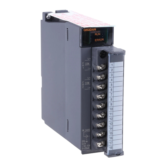
Page 10: Part Names
3. Part Names This section explains the names of the components for the D/A conversion module. Terminal Signal name number Q62DAN Q64DAN ERROR Vacant Vacant Vacant Vacant Vacant Vacant Vacant Vacant Vacant Vacant IN 24VDC Vacant (FG) Vacant -10 10V 20mA 24 V 24 G... - Page 11 Number Name Description RUN LED Displays the operating status of the D/A converter module. : Normal operation Flashing : During offset/gain setting mode : 5V power switched off, watchdog timer error occurred, or online module change enabled ERROR LED Displays the error status of the D/A converter module.
-
Page 12: Handling Precautions
4. Handling Precautions (1) Do not drop the module case or subject it to heavy impact. (2) Do not remove the PCB of the module from its case. Doing so may cause the module to fail. (3) Be careful not to let foreign particles such as swarf or wire chips enter the module. -
Page 13: External Wiring
Point When using Q68DAVN or Q68DAIN, If it is difficult to wire FG terminals due to the limited installation space, use FG terminal L-shaped metal fitting. 5.2 External wiring (1) For Q62DAN or Q64DAN (a) For voltage output Motor drive module, etc. 1 kΩ... - Page 14 (2) For Q68DAVN Motor drive module, etc. 1 kΩ conversion 1 MΩ 24 V DC DC/DC Filter converter (3) For Q68DAIN Motor drive module, etc. 0Ω conversion 600Ω 24 V DC DC/DC Filter converter *1 Use a twisted two core shielded wire for the power wire. *2 If there is noise or ripples in the external wiring, connect a 0.1 to 0.47 F25V capacitor between the V+/I+ terminal and COM.
-
Page 15: Switch Setting For Intelligent Functional Module
5.3 Switch setting for intelligent functional module The settings for the intelligent function module are performed using the I/O allocation settings for the GX Developer. When the intelligent function module switches are not set, the default value for switches 1 to 5 is 0. Setting item Output range setting Output range... - Page 16 Point (1) Depending on the type of module used, the settings for D/A module output range are shown below. • Q62DAN, Q64DAN ..0 to 4 • Q68DAVN....0 to 4 1: When the setting is 0 , the output operating range swill be 1 to 5 V. •...
-
Page 17: External Dimensions
6. External Dimensions (1) Q62DAN Q62DAN ERROR 90 (3.54) 112 (4.41) 27.4 (1.08) Unit: mm (inch) (2) Q64DAN Q64DAN ERROR IN 24VDC (FG) 20mA 90 (3.54) 112 (4.41) 27.4 (1.08) Unit: mm (inch) - Page 18 (3) Q68DAVN Q68DAVN ERROR M3 screw (Accessory) M3 screw (Accessory) 63 (2.48) FG terminal L-Shaped metal fitting (Accessory) 71.5 (2.81) 90 (3.54) 112 (4.41) 27.4 (1.08) Unit: mm (inch) (4) Q68DAIN Q68DAIN ERROR C O M C O M C O M C O M C O M C O M...
- Page 19 MEMO...
- Page 20 Warranty Mitsubishi will not be held liable for damage caused by factors found not to be the cause of Mitsubishi; machine damage or lost profits caused by faults in the Mitsubishi products; damage, secondary damage, accident compensation caused by special factors unpredictable by Mitsubishi;...
Need help?
Do you have a question about the MELSEC-Q Q62DAN and is the answer not in the manual?
Questions and answers